当前位置:网站首页>STM32 serial port register library function configuration method
STM32 serial port register library function configuration method
2022-07-07 08:58:00 【A big cat 1201】
author : A big cat 1201
special column :《STM32 Study 》
Maxim : You just try to , Leave the rest to time !

Serial port register library function configuration method
describe
Communication is required between devices , For example, between single-chip microcomputer and single-chip microcomputer , Between SCM and computer, etc , There are two ways of communication , Serial communication and parallel communication .
Serial communication and parallel communication
Let's talk about the difference between the two
Parallel communication
- - Transmission principle : All bits of data are transmitted at the same time .
- - advantage : Fast
- - shortcoming : It takes up a lot of pin resources
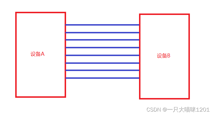
Suppose that the transmission between two devices is a 8 A data , The above figure shows the connection mode of the data lines of the two devices , Eight wires are needed , Two devices account for eight each IO mouth , every last IO Port corresponds to a bit of data .
serial communication
- - Transmission principle : Data transmission in bit order .
- - advantage : Less pin resources
- - shortcoming : Relatively slow
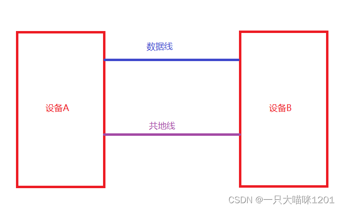
It is also transmission 8 A data , Only one data line is needed to realize data transmission . The other is a common ground .
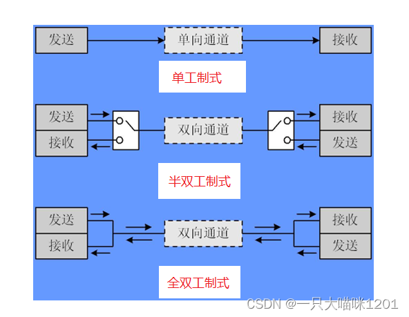
Serial communication mode
- Serial communication is also divided into :
Simplex :
- Data transmission only supports data transmission in one direction
Half duplex :
- Allows data to be transmitted in both directions , however , At some point , Only data can be transmitted in one direction , It's actually a kind of direction switching simplex communication ;
Full duplex system :
- Allows data to be transmitted in both directions at the same time , therefore , Full duplex communication is a combination of two simplex communication modes , It requires that both the transmitting device and the receiving device have independent receiving and transmitting capabilities .
2. According to the data transmission mode, serial communication is divided into :
Synchronous communication : With clock synchronous signal transmission .
- -SPI,IIC communication interface
asynchronous communication : No clock synchronization .
- -UART( Universal asynchronous transceiver ), Single bus
Common serial communication interface :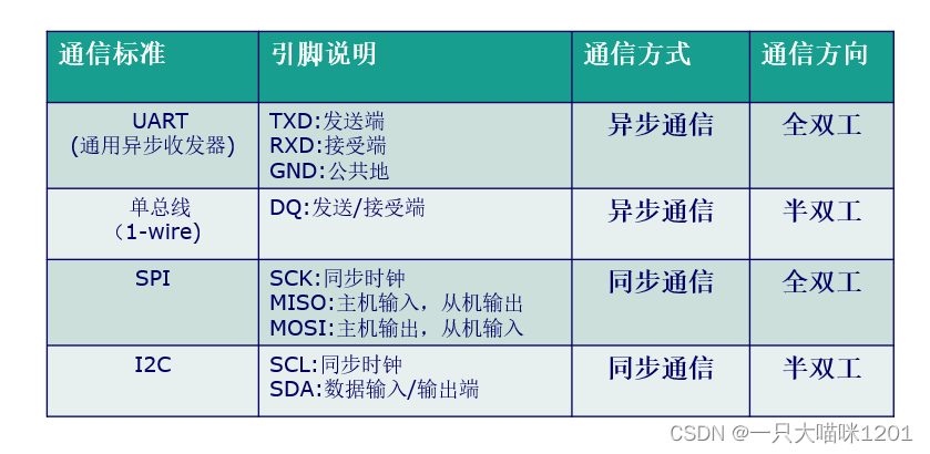
ad locum , Ben meow only talks about asynchronous communication .
Serial asynchronous communication has the following characteristics :
Full duplex asynchronous communication :
- Fractional baud rate generator system , Provide accurate baud rate .
- Send and receive common programmable baud rate , Up to 4.5Mbits/s- Programmable data word length (8 Bits or 9 position );
- Configurable stop bits ( Support 1 perhaps 2 Bit stop bit );
- Configurable use DMA Multi buffer communication .
- Separate transmitter and receiver enable bits .
- Detection marks :① Accept buffer ② Send buffer empty ③ End of transmission flag
- Multiple interrupt sources with flags . Trigger interrupt .
- other : Calibration control , Four error detection flags .
When using asynchronous communication , Parameters need to be set :
- Start bit
- Data bits (8 Bits or 9 position )
- Parity bit ( The first 9 position )
- Stop bit (1,1.5,2 position )
- Baud rate setting
It looks like this 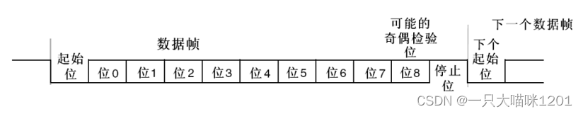
Such a data format is called a frame format .
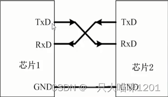
Serial communication wiring
The large capacity STM32F10x Series of chips , contain 3 individual USART( Universal synchronous asynchronous transceiver ) and 2 individual UART( Universal asynchronous transceiver ), in other words , As a serial port for asynchronous communication, there can be 5 individual , Their port multiplexing is shown in the figure below :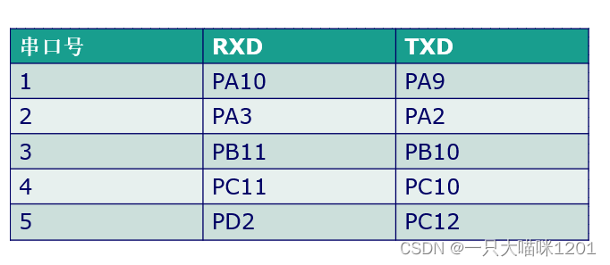
RXD Is the receiver pin ,TXD Is the sender pin .
When wiring , One side RXD With the other party TXD Connected to a , also TXD With the other party RXD Connected to a .
Serial communication structure block diagram
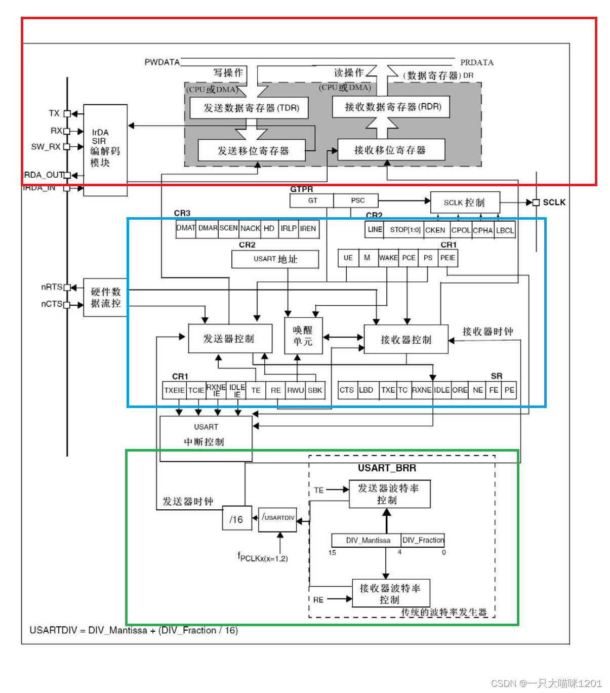
The figure above is the whole structure block diagram of serial communication .
Serial communication process
The red frame in the block diagram is the data receiving and generating process of serial communication .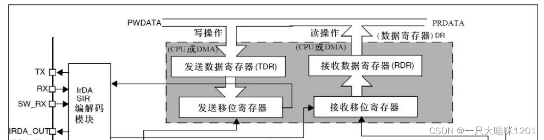
Data transmission :
- When CPU When you want to send a data , First write the data into the transmit data register (TDR) in , Then send the shift register bit by bit , Until the stop bit is encountered, the transmission ends .
Data reception :
- When external data is transmitted ,CPU Need to receive data , At this time, the data is received bit by bit in the receive shift register , Then it is transferred to the receiving data register (RDR) in ,CPU Then read data from this register .
Registers involved in serial communication ( Skipping )
The blue box in the structure block diagram is the register owned by the serial port .
- Status register (USART_SR)
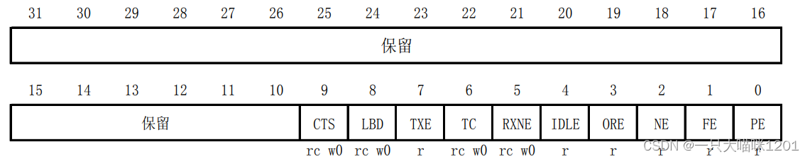
This is it 32 Bit distribution , Only 0 To 9 Bit in use , Other bits are reserved , Each bit used represents a state of serial communication .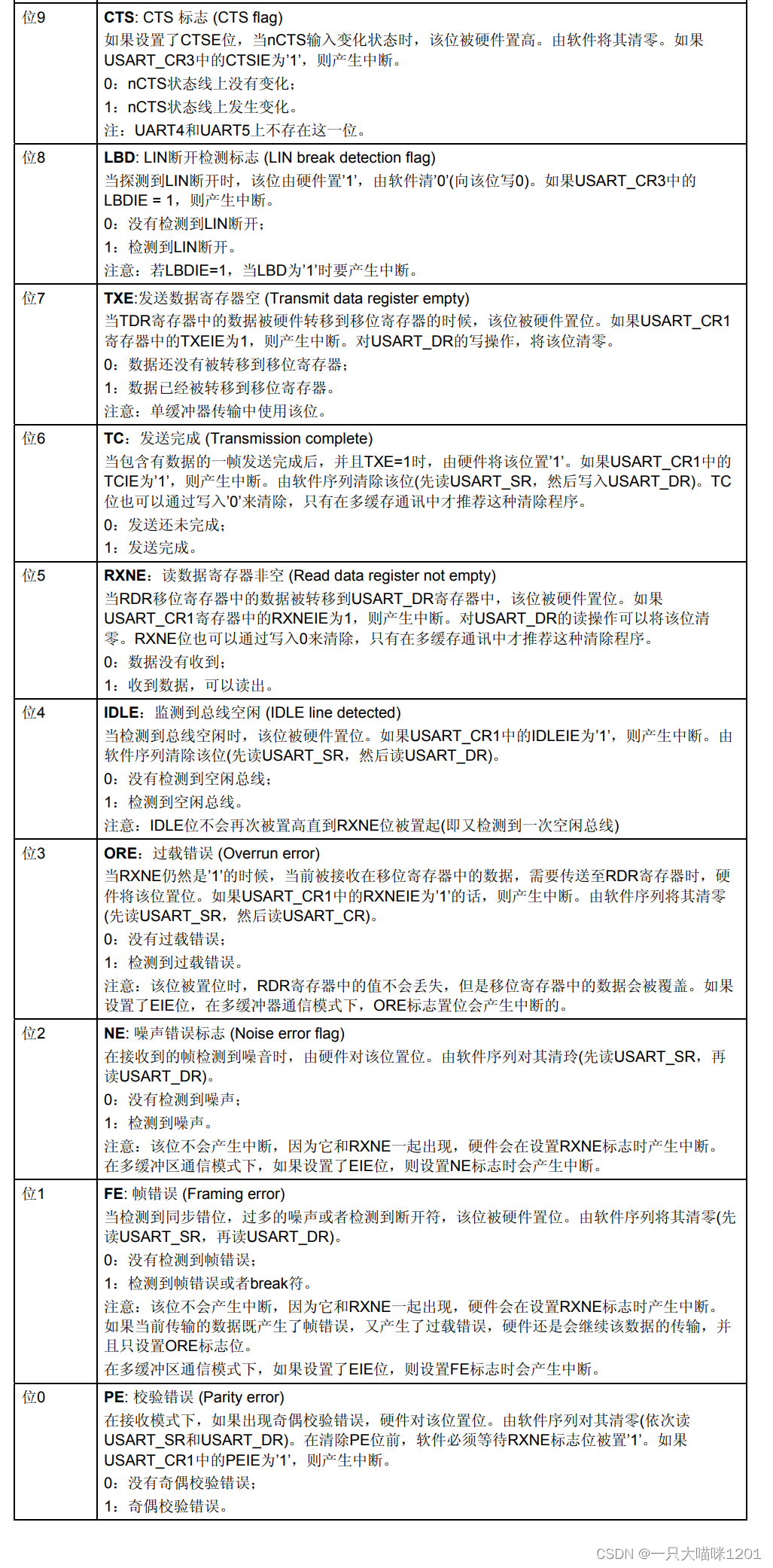
This is what it uses 10 A bit represents the situation of meaning .
In the process of use, some library functions are usually used to query the status of serial communication .
- Data register (USART_DR)
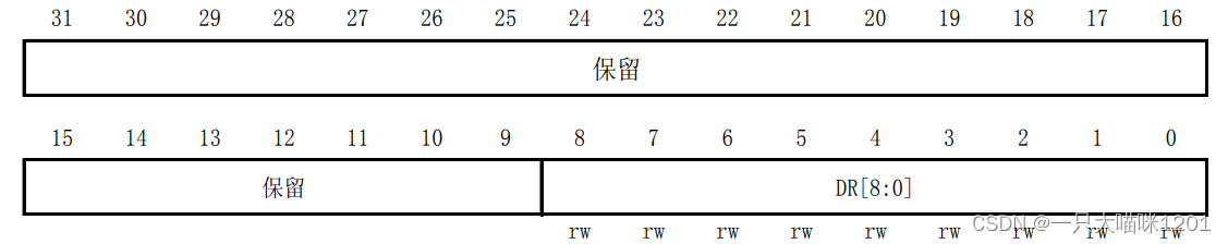
This is it 32 Bit distribution , Only low 8 position , The rest are reserved , the 8 Bits can be read and written . Whether sending data or receiving data is for this 8 Bit to operate .
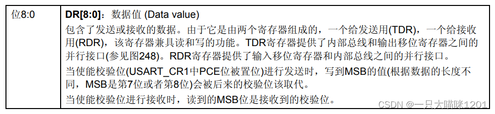
This is a 8 Bit details .
- Control register 1(USART_CR1)
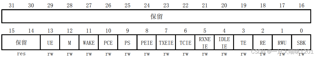
This is it 32 Bit usage , Only low 14 Bit in use , Other bits are reserved .
This is the specific control of each of them .
- Control register 2(USART_CR2)
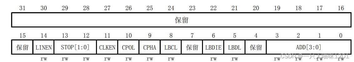
This is it 32 Bit usage , GM only uses low 14 position , Other bits are reserved .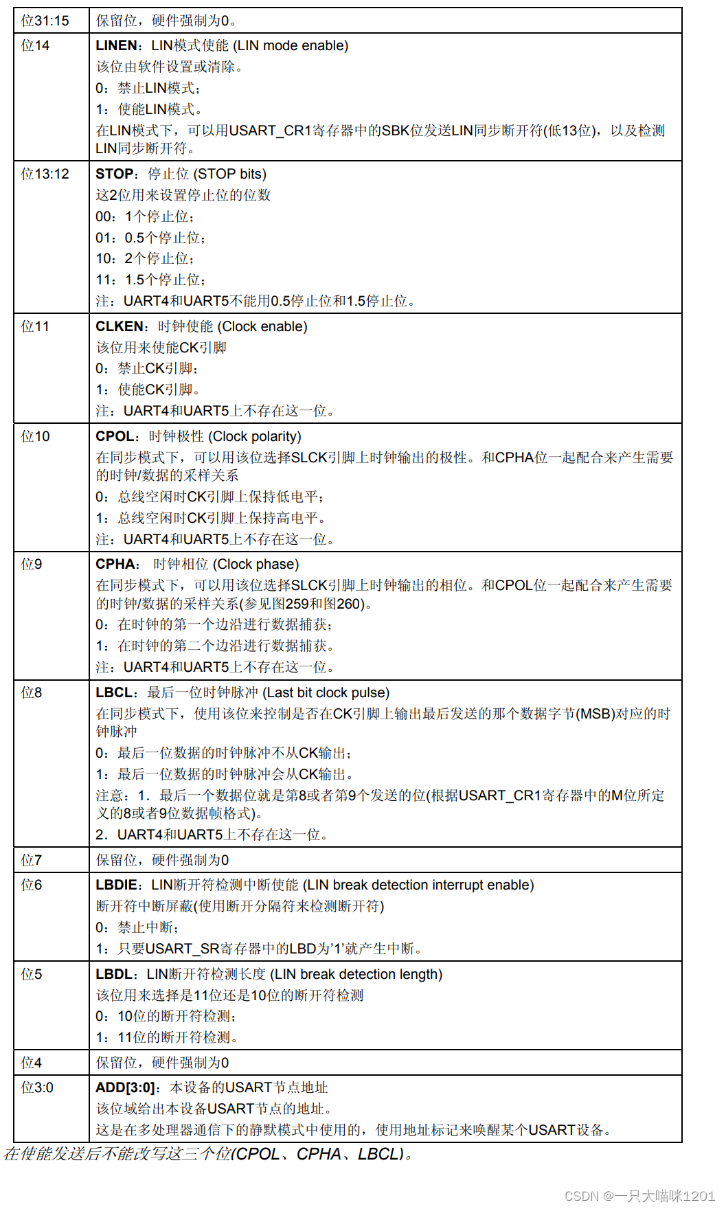
This is the specific control of each of them .
- Control register 3(USART_CR3)
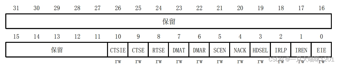
This is it 32 Bit usage , Only the first 11 position , Other bits are reserved .
This is the specific control of each of them .
- Baud ratio register (USART_BRR)
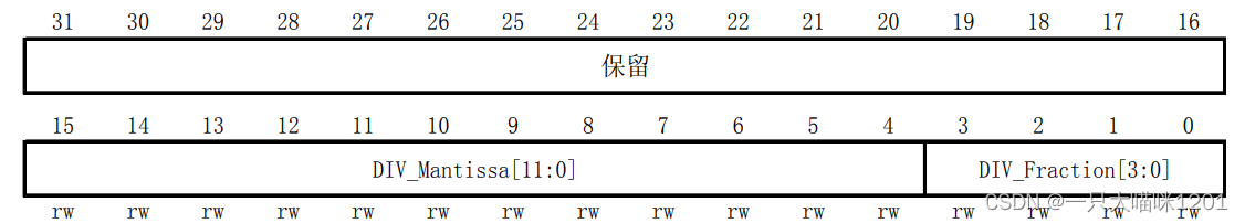
This is it 32 Bit usage , Only low 16 Bit in use , Other bits are reserved .0 To 3 Bit is the fractional part of baud rate ,4 To 15 Bit is the integer part of baud rate .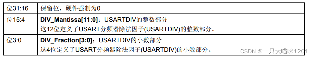
This is the specific meaning of its use of bits .
above 6 A register is a register we often use , Of course, there are other registers , When it comes to use, Ben meow will talk about it in detail .
Baud rate setting
The green frame in the serial connection structure block diagram is used to set the baud rate of serial communication .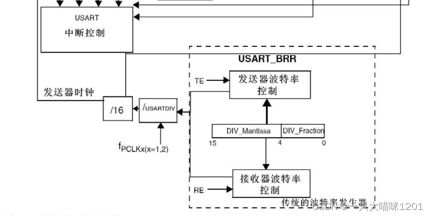
USART1 It uses fPCLK2, Its general frequency is 72MHZ, Others USART It uses fPCLK1, The general frequency is 36MHZ.
The baud rate is fPCLKx Divided by USARTDIV( Division coefficient ), Divided by 16 To come out .
USARTDIV Through register USART_BRR Set the value obtained , It can be a decimal .
Calculation of baud rate
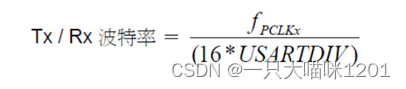
This is the calculation formula of baud rate .
Now let's receive how to pass USARTDIV Get serial port USART_BRR Value in register .
Suppose our serial port 1 The value of baud rate to be set is 115200, and PCLK2 The clock is 72MHZ.
- According to the formula above :
USARTDIV=72000000/(115200*16)=39.0625So get :
- DIV_Fractino = 16*0.0625 = 1 = 0X01;( The fractional part )
DIV_Mantissa = 39 = 0X27;( Integral part )So now we have USART_BRR The value in the register is 0X271. Just set the serial port 1 Of BRR The value of the register is 0X271 You can get 115200 Baud rate .
Pay attention here , The decimal part is multiplied by 16 And then put in USART_BRR Register low 4 In a .
General steps of serial port configuration
- Serial clock enable ,GPIO Clock enable
In this meow's article Port reuse and remapping The reuse of serial port has been explained in detail in the article , Here we use it directly .
RCC_APB2PeriphClockCmd(RCC_APB2Periph_GPIOA,ENABLE);//PA9 and PA10 It's serial 1 Multiplexing port
RCC_APB2PeriphClockCmd(RCC_APB2Periph_USART1,ENABLE);// A serial port 1 Mounted on APB2 On the bus
- GPIO Port mode settings
Due to the port multiplexing function used , So you need to configure , That is to say IO The port is initialized , Also in Port reuse and remapping The reuse of serial port has been explained in detail in the article , Here we use it directly .
GPIO_InitTypeDef GPIO_InitStructe;
GPIO_InitStructe.GPIO_Mode=GPIO_Mode_AF_PP;// Push pull multiplex output
GPIO_InitStructe.GPIO_Pin=GPIO_Pin_9;//PA9 Pin multiplexing is TX
GPIO_InitStructe.GPIO_Speed=GPIO_Speed_10MHz;// Speed doesn't matter
GPIO_Init(GPIOA,&GPIO_InitStructe);//PA9 Pin multiplexing is USART1 Of TX Pin

GPIO_InitStructe.GPIO_Mode=GPIO_Mode_IN_FLOATING;// Floating input
GPIO_InitStructe.GPIO_Pin=GPIO_Pin_10;//PA10 Pin multiplexing is RX
GPIO_InitStructe.GPIO_Speed=GPIO_Speed_10MHz;// Speed doesn't matter
GPIO_Init(GPIOA,&GPIO_InitStructe);//PA10 Pin multiplexing is USART1 Of RX Pin
The above code will USART1 Of TXD and RXD The pins are multiplexed to PA9 and PA10 On .
- Initialization of serial port parameters
USART_InitStructe.USART_BaudRate=115200;// The baud rate is set to 115200
USART_InitStructe.USART_HardwareFlowControl=USART_HardwareFlowControl_None;// No hardware flow control
USART_InitStructe.USART_Mode=USART_Mode_Tx|USART_Mode_Rx;//USART1 Send and receive pins
USART_InitStructe.USART_Parity=USART_Parity_No;// No parity bit
USART_InitStructe.USART_StopBits=USART_StopBits_1;// Stop bit is 1 position
USART_InitStructe.USART_WordLength=USART_WordLength_8b;// Data bit 8 position , No parity bit
USART_Init(USART1,&USART_InitStructe);// Serial port initialization
The above code completes the initialization of the serial port .
- Turn on interrupt and initialize NVIC( If you need to turn on interrupt, you need this step )
In this meow's article NVIC Interrupt priority management The middle level of the article talked about the grouping and use of interrupts .
First, you need to group interrupts in the main function
NVIC_PriorityGroupConfig(NVIC_PriorityGroup_2);// Interrupt grouping uses grouping 2
After the grouping is completed, we need to USART1 Interrupt enable , And set the priority
USART_ITConfig(USART1,USART_IT_RXNE,ENABLE);// Yes USART1 Receive interrupt enable of
The control register above 1(USART_CR1) There is a detailed introduction in the introduction .
Then set the interrupt priority
NVIC_InitTypeDef NVIC_InitStructe;
NVIC_InitStructe.NVIC_IRQChannel=USART1_IRQn;// The interrupt type is USART1 interrupt
NVIC_InitStructe.NVIC_IRQChannelCmd=ENABLE;// Can make
NVIC_InitStructe.NVIC_IRQChannelPreemptionPriority=1;// The preemption priority is set to 1
NVIC_InitStructe.NVIC_IRQChannelSubPriority=1;// The response priority is set to 1
NVIC_Init(&NVIC_InitStructe);// Interrupt priority initialization
- Enable serial port
After all initialization settings are completed, enable the serial port , That is, open the serial port
USART_Cmd(USART1,ENABLE);// Enable serial port , That is, open the serial port
- Write interrupt handling functions
Now the serial port has been opened , We need to write the function after entering the interrupt , That is, what to do after entering the interrupt
void USART1_IRQHandler(void)
{

	u8 ret = 0;
	// Determine whether it is a receive interrupt
	if(USART_GetITStatus(USART1,USART_IT_RXNE))
	{

		ret = USART_ReceiveData(USART1);// Read the value in the data register after receiving interrupt
		USART_SendData(USART1,ret);// Send the received value to the computer
	}
}
The format of the function name of the interrupt handler function must follow this , Because it has been stipulated in the startup document , The return type is empty 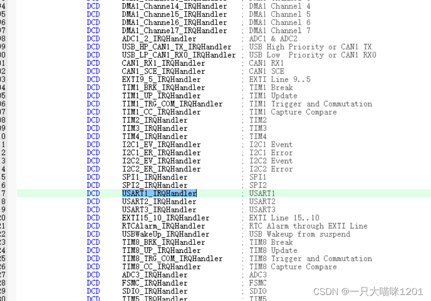
After entering the interrupt , It is possible that the transmission is interrupted , It may also be a receive interrupt , So we need to use
USART_GetITStatus(USART1,USART_IT_RXNE)
This function determines whether the interrupt is a receive interrupt , If so, go back 1, If the return value is 0, The description is sending interrupt , Then the contents in the interrupt processing function will not be executed , Continue to wait for .
The received value is the value we input to the single chip microcomputer on the computer , Then feed this back to the computer .
- Wait for the interrupt to occur
int main(void)
{

	NVIC_PriorityGroupConfig(NVIC_PriorityGroup_2);// Interrupt grouping uses grouping 2
	my_USART_Init();// Carry out a series of initialization of the serial port
	while(1);// Waiting for the interruption to occur
}
above 8 The first step is the whole register library function configuration process of serial port asynchronous communication , After the configuration is completed, you can use
Of course, there are some library functions that are not mentioned in the above process , For example, serial port transmission status acquisition
FlagStatus USART_GetFlagStatus(USART_TypeDef* USARTx, uint16_t USART_FLAG);
void USART_ClearITPendingBit(USART_TypeDef* USARTx, uint16_t USART_IT);
wait , These functions will be explained in detail later when they are used .
Effect display
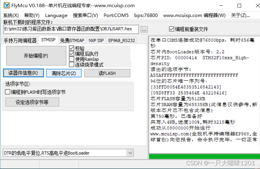
Burn the code to STM32 In the after , Open the serial debugging assistant 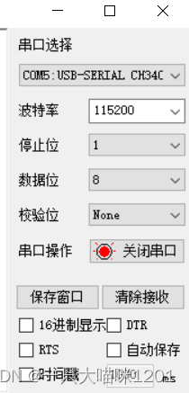
Set the baud rate , Stop bit , Data bits , The check bit and other information are set as the same as those written in our program .
Send information in the send window 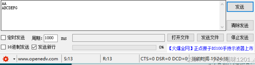
The corresponding information is received in the receiving window 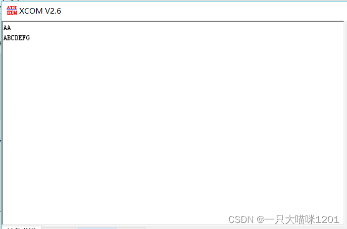
The following is the diagram of the whole interface 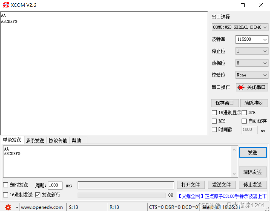
Because single chip microcomputer has no phenomenon , So the status of the development board is not shown here .
summary
The configuration of serial port register and serial communication mainly depends on the use of library functions , Be clear about when to use what library functions , What is its role , As for which register is specifically operated , stay ST After the official provides the corresponding library functions, the understanding of registers is not so important , Just have an impression , In case you can find it when you need it . As long as we strictly follow the configuration process mentioned above, it will be easy to configure , As for the specific use of serial communication , In the later serial communication experiment, we will talk about .
边栏推荐
- 硬件大熊原创合集(2022/06更新)
- Opencv converts 16 bit image data to 8 bits and 8 to 16
- Simulation volume leetcode [general] 1567 Length of the longest subarray whose product is a positive number
- Test pits - what test points should be paid attention to when adding fields to existing interfaces (or database tables)?
- 9c09730c0eea36d495c3ff6efe3708d8
- 徽商期货公司评级是多少?开户安全吗?我想开户,可以吗?
- Three usage scenarios of annotation @configurationproperties
- How to realize sliding operation component in fast application
- Why choose cloud native database
- Problems encountered in the use of go micro
猜你喜欢
STM32串口寄存器库函数配置方法
【Istio Network CRD VirtualService、Envoyfilter】
Introduction to data fragmentation
Category of IP address
H3C VXLAN配置
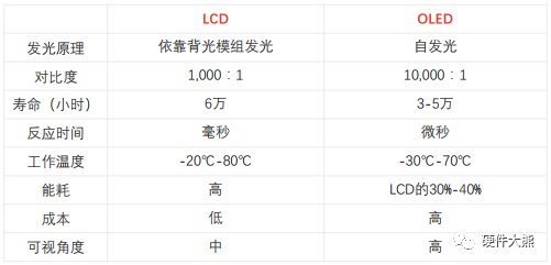
Panel display technology: LCD and OLED
2022-06-30 unity core 8 - model import

Markdown编辑器Editor.md插件的使用

How to realize sliding operation component in fast application
![[step on the pit] Nacos registration has been connected to localhost:8848, no available server](/img/ee/ab4d62745929acec2f5ba57155b3fa.png)
[step on the pit] Nacos registration has been connected to localhost:8848, no available server
随机推荐
指针进阶,字符串函数
[Yugong series] February 2022 U3D full stack class 008 - build a galaxy scene
QT charts use (rewrite qchartview to realize some custom functions)
Personal deduction topic classification record
Speaking of a software entrepreneurship project, is there anyone willing to invest?
Mock. JS usage details
Output all composite numbers between 6 and 1000
模拟卷Leetcode【普通】1557. 可以到达所有点的最少点数目
Simulation volume leetcode [general] 1706 Where does the ball meet
Category of IP address
2022-07-06 unity core 9 - 3D animation
Mountaineering team (DFS)
Redis fault handling "can't save in background: fork: cannot allocate memory“
Why choose cloud native database
Platformization, a fulcrum of strong chain complementing chain
Sign and authenticate API interface or H5 interface
Gson converts the entity class to JSON times declare multiple JSON fields named
求有符号数的原码、反码和补码【C语言】
How to count the number of project code lines
个人力扣题目分类记录