当前位置:网站首页>The Hal library is configured with a general timer Tim to trigger ADC sampling, and then DMA is moved to the memory space.
The Hal library is configured with a general timer Tim to trigger ADC sampling, and then DMA is moved to the memory space.
2022-07-07 10:14:00 【Xiao Li is clean and sanitary】
ADC+TIM+DMA
1. brief introduction
HAL The library is configured with a general timer TIM Trigger ADC sampling , then DMA Move to memory space .
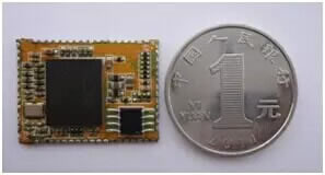
MCU by STM32F429
ADC The trigger of can be configured as external trigger conversion
![[ Failed to transfer the external chain picture , The origin station may have anti-theft chain mechanism , It is suggested to save the pictures and upload them directly (img-tFktjPYf-1656982815084)(https://raw.githubusercontent.com/Master-4869/pictures/main/image-20220704210218702.png)]](/img/88/613fb106355edde696d3c1fb3ae885.png)
![[ Failed to transfer the external chain picture , The origin station may have anti-theft chain mechanism , It is suggested to save the pictures and upload them directly (img-eVeuhPNf-1656982815085)(https://raw.githubusercontent.com/Master-4869/pictures/main/image-20220704210230784.png)]](/img/9e/450aebbe972059a64d6e00ebd2250c.png)
Support timer as trigger source ,
![[ Failed to transfer the external chain picture , The origin station may have anti-theft chain mechanism , It is suggested to save the pictures and upload them directly (img-FM9xrPPO-1656982815086)(https://raw.githubusercontent.com/Master-4869/pictures/main/image-20220704210425246.png)]](/img/0e/d41dfb7a02de203c56115e1b71cf6e.png)
The output of the timer can also be configured GPIO Pin , Specially select an output channel as the trigger source to control ADC Sampling of .
2.cubemx Configuration and code
cubemx The version is 6.6.0
mdk The version is 5.34
ADC To configure
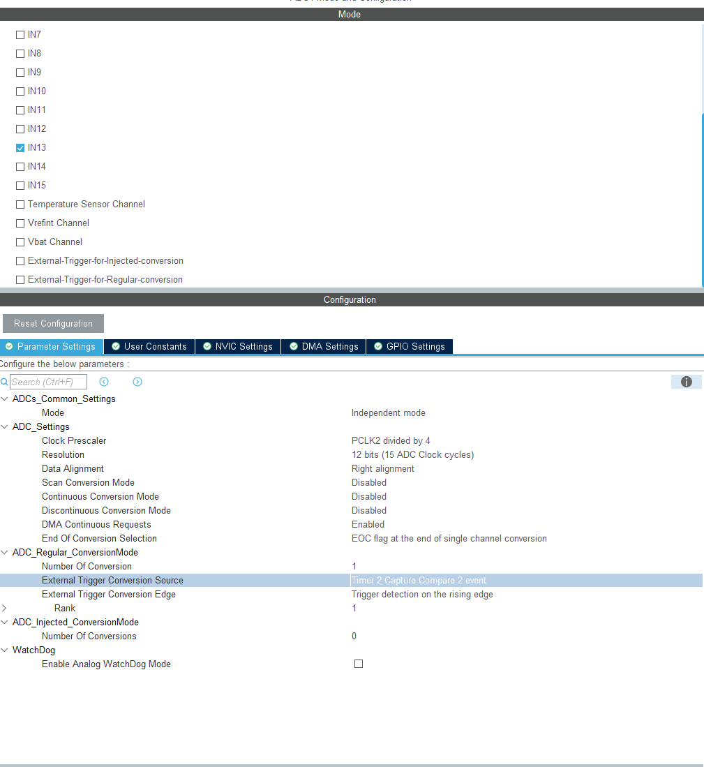
Because to use TIM To trigger ADC, So turn off continuous mode , Select the trigger option below TIM2 The passage of 2, Trigger edge select the rising edge to trigger .
DMA To configure
![[ Failed to transfer the external chain picture , The origin station may have anti-theft chain mechanism , It is suggested to save the pictures and upload them directly (img-EljW2Uqt-1656982815086)(https://raw.githubusercontent.com/Master-4869/pictures/main/image-20220704211910222.png)]](/img/cb/a4b18c6cd3971c51534bb57b584a06.png)
To select the cycle mode , otherwise DMA Only one transmission will end , If not, it will trigger ADC The result of constantly moving data .
Timer configuration .
![[ Failed to transfer the external chain picture , The origin station may have anti-theft chain mechanism , It is suggested to save the pictures and upload them directly (img-iDRLff1b-1656982815087)(https://raw.githubusercontent.com/Master-4869/pictures/main/image-20220704212059245.png)]](/img/1c/2b46f9c2647b202dd87ac8d26d70ec.png)
because ADC Is triggered by the rising edge , Timer can be used PWM The output mode , It is convenient to design the output frequency ,TIM2 passageway 2 Set to no external output mode , use PSC Set the frequency to 1M, Then set the frequency to 500ms, The duty cycle is set to 50%, In fact, the duty cycle is useless , Because only the rising edge will trigger sampling .
/* USER CODE BEGIN Header */
/** ****************************************************************************** * @file adc.c * @brief This file provides code for the configuration * of the ADC instances. ****************************************************************************** * @attention * * Copyright (c) 2022 STMicroelectronics. * All rights reserved. * * This software is licensed under terms that can be found in the LICENSE file * in the root directory of this software component. * If no LICENSE file comes with this software, it is provided AS-IS. * ****************************************************************************** */
/* USER CODE END Header */
/* Includes ------------------------------------------------------------------*/
#include "adc.h"

/* USER CODE BEGIN 0 */

/* USER CODE END 0 */

ADC_HandleTypeDef hadc1;
DMA_HandleTypeDef hdma_adc1;

/* ADC1 init function */
void MX_ADC1_Init(void)
{


  /* USER CODE BEGIN ADC1_Init 0 */

  /* USER CODE END ADC1_Init 0 */

  ADC_ChannelConfTypeDef sConfig = {
    0};

  /* USER CODE BEGIN ADC1_Init 1 */

  /* USER CODE END ADC1_Init 1 */

  /** Configure the global features of the ADC (Clock, Resolution, Data Alignment and number of conversion) */
  hadc1.Instance = ADC1;
  hadc1.Init.ClockPrescaler = ADC_CLOCK_SYNC_PCLK_DIV4;
  hadc1.Init.Resolution = ADC_RESOLUTION_12B;
  hadc1.Init.ScanConvMode = DISABLE;
  hadc1.Init.ContinuousConvMode = DISABLE;
  hadc1.Init.DiscontinuousConvMode = DISABLE;
  hadc1.Init.ExternalTrigConvEdge = ADC_EXTERNALTRIGCONVEDGE_RISING;
  hadc1.Init.ExternalTrigConv = ADC_EXTERNALTRIGCONV_T2_CC2;
  hadc1.Init.DataAlign = ADC_DATAALIGN_RIGHT;
  hadc1.Init.NbrOfConversion = 1;
  hadc1.Init.DMAContinuousRequests = ENABLE;
  hadc1.Init.EOCSelection = ADC_EOC_SINGLE_CONV;
  if (HAL_ADC_Init(&hadc1) != HAL_OK)
  {

    Error_Handler();
  }

  /** Configure for the selected ADC regular channel its corresponding rank in the sequencer and its sample time. */
  sConfig.Channel = ADC_CHANNEL_13;
  sConfig.Rank = 1;
  sConfig.SamplingTime = ADC_SAMPLETIME_3CYCLES;
  if (HAL_ADC_ConfigChannel(&hadc1, &sConfig) != HAL_OK)
  {

    Error_Handler();
  }
  /* USER CODE BEGIN ADC1_Init 2 */

  /* USER CODE END ADC1_Init 2 */

}

void HAL_ADC_MspInit(ADC_HandleTypeDef* adcHandle)
{


  GPIO_InitTypeDef GPIO_InitStruct = {
    0};
  if(adcHandle->Instance==ADC1)
  {

  /* USER CODE BEGIN ADC1_MspInit 0 */

  /* USER CODE END ADC1_MspInit 0 */
    /* ADC1 clock enable */
    __HAL_RCC_ADC1_CLK_ENABLE();

    __HAL_RCC_GPIOC_CLK_ENABLE();
    /**ADC1 GPIO Configuration PC3 ------> ADC1_IN13 */
    GPIO_InitStruct.Pin = GPIO_PIN_3;
    GPIO_InitStruct.Mode = GPIO_MODE_ANALOG;
    GPIO_InitStruct.Pull = GPIO_NOPULL;
    HAL_GPIO_Init(GPIOC, &GPIO_InitStruct);

    /* ADC1 DMA Init */
    /* ADC1 Init */
    hdma_adc1.Instance = DMA2_Stream0;
    hdma_adc1.Init.Channel = DMA_CHANNEL_0;
    hdma_adc1.Init.Direction = DMA_PERIPH_TO_MEMORY;
    hdma_adc1.Init.PeriphInc = DMA_PINC_DISABLE;
    hdma_adc1.Init.MemInc = DMA_MINC_ENABLE;
    hdma_adc1.Init.PeriphDataAlignment = DMA_PDATAALIGN_HALFWORD;
    hdma_adc1.Init.MemDataAlignment = DMA_MDATAALIGN_HALFWORD;
    hdma_adc1.Init.Mode = DMA_CIRCULAR;
    hdma_adc1.Init.Priority = DMA_PRIORITY_LOW;
    hdma_adc1.Init.FIFOMode = DMA_FIFOMODE_DISABLE;
    if (HAL_DMA_Init(&hdma_adc1) != HAL_OK)
    {

      Error_Handler();
    }

    __HAL_LINKDMA(adcHandle,DMA_Handle,hdma_adc1);

  /* USER CODE BEGIN ADC1_MspInit 1 */

  /* USER CODE END ADC1_MspInit 1 */
  }
}

void HAL_ADC_MspDeInit(ADC_HandleTypeDef* adcHandle)
{


  if(adcHandle->Instance==ADC1)
  {

  /* USER CODE BEGIN ADC1_MspDeInit 0 */

  /* USER CODE END ADC1_MspDeInit 0 */
    /* Peripheral clock disable */
    __HAL_RCC_ADC1_CLK_DISABLE();

    /**ADC1 GPIO Configuration PC3 ------> ADC1_IN13 */
    HAL_GPIO_DeInit(GPIOC, GPIO_PIN_3);

    /* ADC1 DMA DeInit */
    HAL_DMA_DeInit(adcHandle->DMA_Handle);
  /* USER CODE BEGIN ADC1_MspDeInit 1 */

  /* USER CODE END ADC1_MspDeInit 1 */
  }
}

/* USER CODE BEGIN 1 */

/* USER CODE END 1 */
/* USER CODE BEGIN Header */
/** ****************************************************************************** * @file dma.c * @brief This file provides code for the configuration * of all the requested memory to memory DMA transfers. ****************************************************************************** * @attention * * Copyright (c) 2022 STMicroelectronics. * All rights reserved. * * This software is licensed under terms that can be found in the LICENSE file * in the root directory of this software component. * If no LICENSE file comes with this software, it is provided AS-IS. * ****************************************************************************** */
/* USER CODE END Header */

/* Includes ------------------------------------------------------------------*/
#include "dma.h"

/* USER CODE BEGIN 0 */

/* USER CODE END 0 */

/*----------------------------------------------------------------------------*/
/* Configure DMA */
/*----------------------------------------------------------------------------*/

/* USER CODE BEGIN 1 */

/* USER CODE END 1 */

/** * Enable DMA controller clock */
void MX_DMA_Init(void)
{


  /* DMA controller clock enable */
  __HAL_RCC_DMA2_CLK_ENABLE();

  /* DMA interrupt init */
  /* DMA2_Stream0_IRQn interrupt configuration */
  HAL_NVIC_SetPriority(DMA2_Stream0_IRQn, 0, 0);
  HAL_NVIC_EnableIRQ(DMA2_Stream0_IRQn);

}

/* USER CODE BEGIN 2 */

/* USER CODE END 2 */
/* USER CODE BEGIN Header */
/** ****************************************************************************** * @file tim.c * @brief This file provides code for the configuration * of the TIM instances. ****************************************************************************** * @attention * * Copyright (c) 2022 STMicroelectronics. * All rights reserved. * * This software is licensed under terms that can be found in the LICENSE file * in the root directory of this software component. * If no LICENSE file comes with this software, it is provided AS-IS. * ****************************************************************************** */
/* USER CODE END Header */
/* Includes ------------------------------------------------------------------*/
#include "tim.h"

/* USER CODE BEGIN 0 */

/* USER CODE END 0 */

TIM_HandleTypeDef htim2;

/* TIM2 init function */
void MX_TIM2_Init(void)
{


  /* USER CODE BEGIN TIM2_Init 0 */

  /* USER CODE END TIM2_Init 0 */

  TIM_ClockConfigTypeDef sClockSourceConfig = {
    0};
  TIM_MasterConfigTypeDef sMasterConfig = {
    0};
  TIM_OC_InitTypeDef sConfigOC = {
    0};

  /* USER CODE BEGIN TIM2_Init 1 */

  /* USER CODE END TIM2_Init 1 */
  htim2.Instance = TIM2;
  htim2.Init.Prescaler = 45;
  htim2.Init.CounterMode = TIM_COUNTERMODE_UP;
  htim2.Init.Period = 500000-1;
  htim2.Init.ClockDivision = TIM_CLOCKDIVISION_DIV1;
  htim2.Init.AutoReloadPreload = TIM_AUTORELOAD_PRELOAD_DISABLE;
  if (HAL_TIM_Base_Init(&htim2) != HAL_OK)
  {

    Error_Handler();
  }
  sClockSourceConfig.ClockSource = TIM_CLOCKSOURCE_INTERNAL;
  if (HAL_TIM_ConfigClockSource(&htim2, &sClockSourceConfig) != HAL_OK)
  {

    Error_Handler();
  }
  if (HAL_TIM_PWM_Init(&htim2) != HAL_OK)
  {

    Error_Handler();
  }
  sMasterConfig.MasterOutputTrigger = TIM_TRGO_OC2REF;
  sMasterConfig.MasterSlaveMode = TIM_MASTERSLAVEMODE_ENABLE;
  if (HAL_TIMEx_MasterConfigSynchronization(&htim2, &sMasterConfig) != HAL_OK)
  {

    Error_Handler();
  }
  sConfigOC.OCMode = TIM_OCMODE_PWM1;
  sConfigOC.Pulse = 250000-1;
  sConfigOC.OCPolarity = TIM_OCPOLARITY_HIGH;
  sConfigOC.OCFastMode = TIM_OCFAST_DISABLE;
  if (HAL_TIM_PWM_ConfigChannel(&htim2, &sConfigOC, TIM_CHANNEL_2) != HAL_OK)
  {

    Error_Handler();
  }
  /* USER CODE BEGIN TIM2_Init 2 */

  /* USER CODE END TIM2_Init 2 */

}

void HAL_TIM_Base_MspInit(TIM_HandleTypeDef* tim_baseHandle)
{


  if(tim_baseHandle->Instance==TIM2)
  {

  /* USER CODE BEGIN TIM2_MspInit 0 */

  /* USER CODE END TIM2_MspInit 0 */
    /* TIM2 clock enable */
    __HAL_RCC_TIM2_CLK_ENABLE();
  /* USER CODE BEGIN TIM2_MspInit 1 */

  /* USER CODE END TIM2_MspInit 1 */
  }
}

void HAL_TIM_Base_MspDeInit(TIM_HandleTypeDef* tim_baseHandle)
{


  if(tim_baseHandle->Instance==TIM2)
  {

  /* USER CODE BEGIN TIM2_MspDeInit 0 */

  /* USER CODE END TIM2_MspDeInit 0 */
    /* Peripheral clock disable */
    __HAL_RCC_TIM2_CLK_DISABLE();
  /* USER CODE BEGIN TIM2_MspDeInit 1 */

  /* USER CODE END TIM2_MspDeInit 1 */
  }
}

/* USER CODE BEGIN 1 */

/* USER CODE END 1 */
/* USER CODE BEGIN Header */
/** ****************************************************************************** * @file : main.c * @brief : Main program body ****************************************************************************** * @attention * * Copyright (c) 2022 STMicroelectronics. * All rights reserved. * * This software is licensed under terms that can be found in the LICENSE file * in the root directory of this software component. * If no LICENSE file comes with this software, it is provided AS-IS. * ****************************************************************************** */
/* USER CODE END Header */
/* Includes ------------------------------------------------------------------*/
#include "main.h"
#include "adc.h"
#include "dma.h"
#include "tim.h"
#include "usart.h"
#include "gpio.h"

/* Private includes ----------------------------------------------------------*/
/* USER CODE BEGIN Includes */

/* USER CODE END Includes */

/* Private typedef -----------------------------------------------------------*/
/* USER CODE BEGIN PTD */

/* USER CODE END PTD */

/* Private define ------------------------------------------------------------*/
/* USER CODE BEGIN PD */
uint16_t adc_buffer[1] = {
    0};
/* USER CODE END PD */

/* Private macro -------------------------------------------------------------*/
/* USER CODE BEGIN PM */

/* USER CODE END PM */

/* Private variables ---------------------------------------------------------*/

/* USER CODE BEGIN PV */

/* USER CODE END PV */

/* Private function prototypes -----------------------------------------------*/
void SystemClock_Config(void);
/* USER CODE BEGIN PFP */

/* USER CODE END PFP */

/* Private user code ---------------------------------------------------------*/
/* USER CODE BEGIN 0 */

/* USER CODE END 0 */

/** * @brief The application entry point. * @retval int */
int main(void)
{

  /* USER CODE BEGIN 1 */

  /* USER CODE END 1 */

  /* MCU Configuration--------------------------------------------------------*/

  /* Reset of all peripherals, Initializes the Flash interface and the Systick. */
  HAL_Init();

  /* USER CODE BEGIN Init */

  /* USER CODE END Init */

  /* Configure the system clock */
  SystemClock_Config();

  /* USER CODE BEGIN SysInit */

  /* USER CODE END SysInit */

  /* Initialize all configured peripherals */
  MX_GPIO_Init();
  MX_DMA_Init();
  MX_ADC1_Init();
  MX_USART1_UART_Init();
  MX_TIM2_Init();
  /* USER CODE BEGIN 2 */
	HAL_ADC_Start_DMA(&hadc1,(uint32_t *)&adc_buffer,1);
	HAL_TIM_PWM_Start(&htim2, TIM_CHANNEL_2);
  /* USER CODE END 2 */

  /* Infinite loop */
  /* USER CODE BEGIN WHILE */
  while (1)
  {

		printf("\r\n-----------\r\n");
		HAL_Delay(5000);
    /* USER CODE END WHILE */

    /* USER CODE BEGIN 3 */
  }
  /* USER CODE END 3 */
}

/** * @brief System Clock Configuration * @retval None */
void SystemClock_Config(void)
{

  RCC_OscInitTypeDef RCC_OscInitStruct = {
    0};
  RCC_ClkInitTypeDef RCC_ClkInitStruct = {
    0};

  /** Configure the main internal regulator output voltage */
  __HAL_RCC_PWR_CLK_ENABLE();
  __HAL_PWR_VOLTAGESCALING_CONFIG(PWR_REGULATOR_VOLTAGE_SCALE1);

  /** Initializes the RCC Oscillators according to the specified parameters * in the RCC_OscInitTypeDef structure. */
  RCC_OscInitStruct.OscillatorType = RCC_OSCILLATORTYPE_HSE;
  RCC_OscInitStruct.HSEState = RCC_HSE_ON;
  RCC_OscInitStruct.PLL.PLLState = RCC_PLL_ON;
  RCC_OscInitStruct.PLL.PLLSource = RCC_PLLSOURCE_HSE;
  RCC_OscInitStruct.PLL.PLLM = 15;
  RCC_OscInitStruct.PLL.PLLN = 216;
  RCC_OscInitStruct.PLL.PLLP = RCC_PLLP_DIV2;
  RCC_OscInitStruct.PLL.PLLQ = 4;
  if (HAL_RCC_OscConfig(&RCC_OscInitStruct) != HAL_OK)
  {

    Error_Handler();
  }

  /** Activate the Over-Drive mode */
  if (HAL_PWREx_EnableOverDrive() != HAL_OK)
  {

    Error_Handler();
  }

  /** Initializes the CPU, AHB and APB buses clocks */
  RCC_ClkInitStruct.ClockType = RCC_CLOCKTYPE_HCLK|RCC_CLOCKTYPE_SYSCLK
                              |RCC_CLOCKTYPE_PCLK1|RCC_CLOCKTYPE_PCLK2;
  RCC_ClkInitStruct.SYSCLKSource = RCC_SYSCLKSOURCE_PLLCLK;
  RCC_ClkInitStruct.AHBCLKDivider = RCC_SYSCLK_DIV1;
  RCC_ClkInitStruct.APB1CLKDivider = RCC_HCLK_DIV4;
  RCC_ClkInitStruct.APB2CLKDivider = RCC_HCLK_DIV2;

  if (HAL_RCC_ClockConfig(&RCC_ClkInitStruct, FLASH_LATENCY_5) != HAL_OK)
  {

    Error_Handler();
  }
}

/* USER CODE BEGIN 4 */
void HAL_ADC_ConvCpltCallback(ADC_HandleTypeDef* hadc)
{

	printf("ADC %d \r\n",adc_buffer[0]);
}
/* USER CODE END 4 */

/** * @brief This function is executed in case of error occurrence. * @retval None */
void Error_Handler(void)
{

  /* USER CODE BEGIN Error_Handler_Debug */
  /* User can add his own implementation to report the HAL error return state */
  __disable_irq();
  while (1)
  {

  }
  /* USER CODE END Error_Handler_Debug */
}

#ifdef USE_FULL_ASSERT
/** * @brief Reports the name of the source file and the source line number * where the assert_param error has occurred. * @param file: pointer to the source file name * @param line: assert_param error line source number * @retval None */
void assert_failed(uint8_t *file, uint32_t line)
{

  /* USER CODE BEGIN 6 */
  /* User can add his own implementation to report the file name and line number, ex: printf("Wrong parameters value: file %s on line %d\r\n", file, line) */
  /* USER CODE END 6 */
}
#endif /* USE_FULL_ASSERT */
DMA There will be an interrupt at the end or half of the transmission , You can configure the interrupt callback function to automatically print out through the serial port after the transmission is completed ADC Sampled data .HAL Library implementation DMA The way to interrupt the service function of is a little complicated .
First, in the stm32f4xx_it.c You can find DMA The interrupt service function of
void DMA2_Stream0_IRQHandler(void)
{
  /* USER CODE BEGIN DMA2_Stream0_IRQn 0 */

  /* USER CODE END DMA2_Stream0_IRQn 0 */
  HAL_DMA_IRQHandler(&hdma_adc1);
  /* USER CODE BEGIN DMA2_Stream0_IRQn 1 */

  /* USER CODE END DMA2_Stream0_IRQn 1 */
}
In interrupt service function HAL_DMA_IRQHandler You can see that some callback functions are called
![[ Failed to transfer the external chain picture , The origin station may have anti-theft chain mechanism , It is suggested to save the pictures and upload them directly (img-XzqAWBKb-1656982815087)(https://raw.githubusercontent.com/Master-4869/pictures/main/image-20220704213743233.png)]](/img/d9/451d4909236148fda3d5d822e46179.png)
DMA There are many callback functions for , Different interrupt states use different callback functions , But these functions are undefined , The definition of function is not in DMA Is responsible for , Because it's not just ADC have access to DMA, For example, serial port can also be used DMA, Everyone has interruption of transmission status ,DMA It can't be fully realized in your own files , So let's use DMA Set the callback function with these peripherals .
![[ Failed to transfer the external chain picture , The origin station may have anti-theft chain mechanism , It is suggested to save the pictures and upload them directly (img-Z9EiKF4N-1656982815087)(https://raw.githubusercontent.com/Master-4869/pictures/main/image-20220704213846230.png)]](/img/01/1ee64ff840862794da82d364931b0c.png)
Look again, open ADC_DMA Function of HAL_ADC_Start_DMA
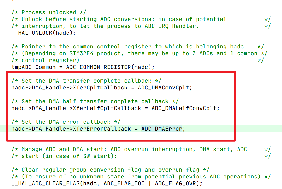
Find that this function puts some ADC Proprietary functions are assigned to DMA These empty callback functions , Similarly, other peripherals should also use this method to assign this peripheral specific function to DMA Above the callback function of .
Look again. ADC_DMAConvCplt,ADC Callback function for data transmission completion
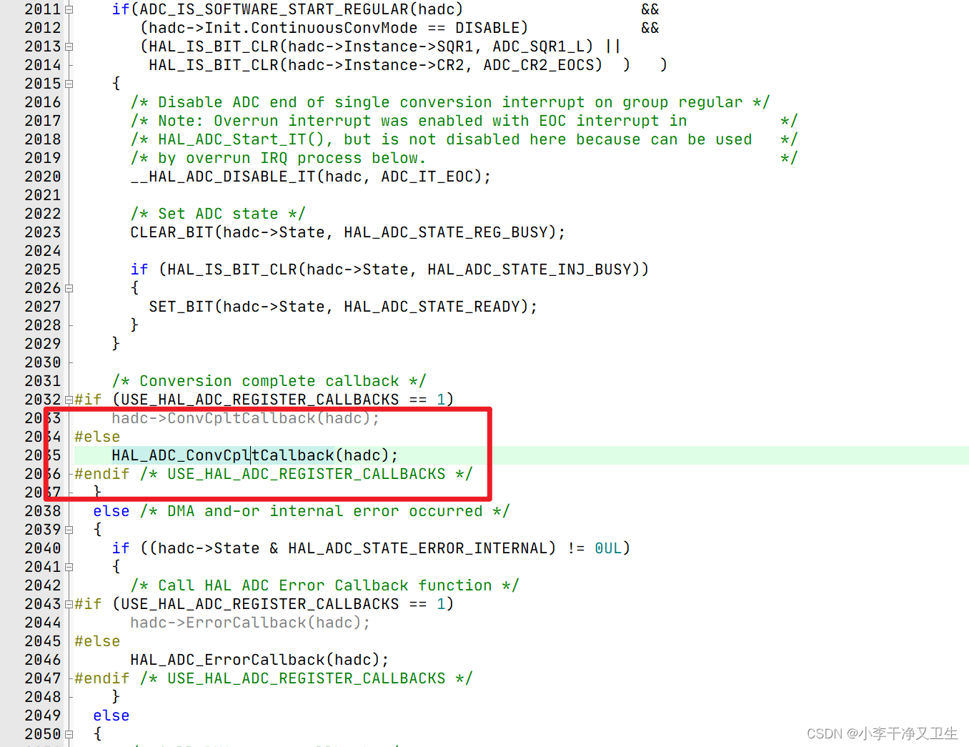
In this function, I found a callback function that really needs to be written by myself HAL_ADC_ConvCpltCallback(hadc);
![[ Failed to transfer the external chain picture , The origin station may have anti-theft chain mechanism , It is suggested to save the pictures and upload them directly (img-UWM9Upn7-1656982815088)(https://raw.githubusercontent.com/Master-4869/pictures/main/image-20220704214904184.png)]](/img/9b/9b4a0028aabe89e0bf62275f7a3a14.png)
This function is weakly defined , If there is no redefinition, the weak definition will prevail , If it is redefined, the newly defined function will prevail , This function can be redefined to implement the functions we want to implement in interrupts .
such as , Each time the transmission is completed, the serial port will send the data .
void HAL_ADC_ConvCpltCallback(ADC_HandleTypeDef* hadc)
{

	printf("ADC %d \r\n",adc_buffer[0]);
}
![[ Failed to transfer the external chain picture , The origin station may have anti-theft chain mechanism , It is suggested to save the pictures and upload them directly (img-XzctgpIx-1656982815088)(https://raw.githubusercontent.com/Master-4869/pictures/main/1111111.gif)]](https://img-blog.csdnimg.cn/6df69364bc1046a8aace18c11488184f.gif)
The whole project has been uploaded
边栏推荐
- phpcms实现PC网站接入微信Native支付
- Future development blueprint of agriculture and animal husbandry -- vertical agriculture + artificial meat
- 中国首款电音音频类“山野电音”数藏发售来了!
- Google Colab装载Google Drive(Google Colab中使用Google Drive)
- Flinkcdc failed to collect Oracle in the snapshot stage. How do you adjust this?
- Google colab loads Google drive (Google drive is used in Google colab)
- Parameter sniffing (1/2)
- 基于gis三维可视化技术的智慧城市建设
- ES6中的函数进阶学习
- MCU与MPU的区别
猜你喜欢
嵌入式背景知识-芯片
XML配置文件解析与建模
![[original] what is the core of programmer team management?](/img/11/d4b9929e8aadcaee019f656cb3b9fb.png)
[original] what is the core of programmer team management?
![[untitled]](/img/5b/61efbaded29250bc8d921b0cf087c8.png)
[untitled]
Applet sliding, clicking and switching simple UI

Chris Lattner, père de llvm: Pourquoi reconstruire le logiciel d'infrastructure ai
How to cancel automatic saving of changes in sqlyog database
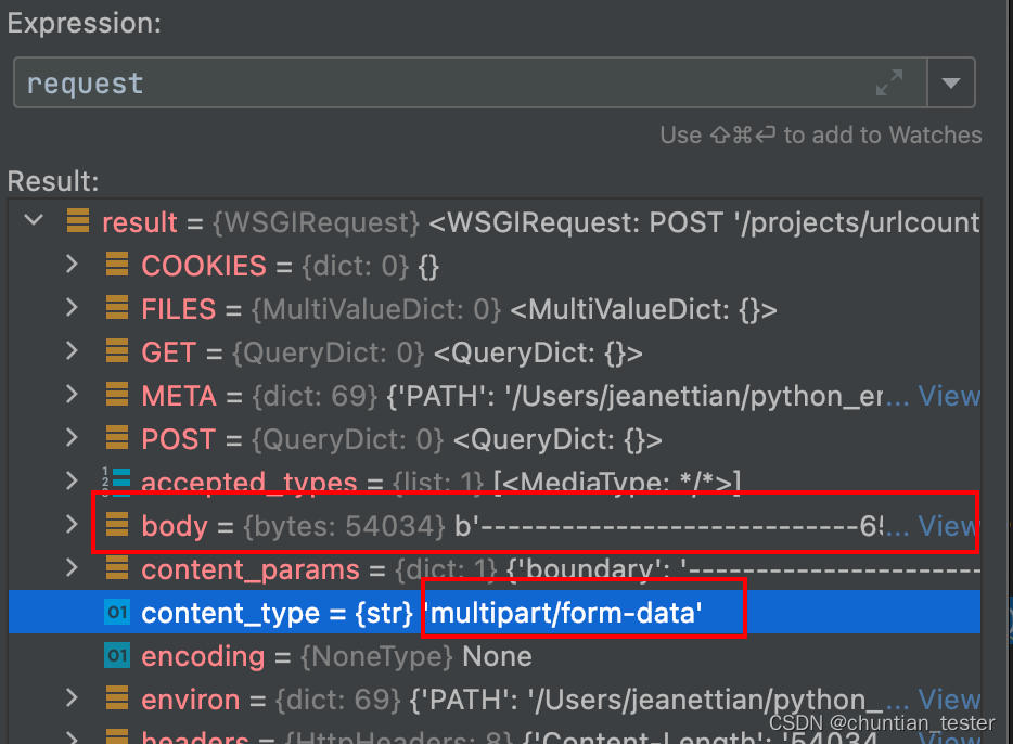
The request object parses the request body and request header parameters
ORM -- database addition, deletion, modification and query operation logic
Programming features of ISP, IAP, ICP, JTAG and SWD
随机推荐
Wallys/IPQ6010 (IPQ6018 FAMILY) EMBEDDED BOARD WITH ON-BOARD WIFI DUAL BAND DUAL CONCURRENT
一文讲解单片机、ARM、MUC、DSP、FPGA、嵌入式错综复杂的关系
Or in SQL, what scenarios will lead to full table scanning
ORM -- logical relation and & or; Sort operation, update record operation, delete record operation
Win10 installation vs2015
Advanced function learning in ES6
Use of JSON extractor originals in JMeter
Applet sliding, clicking and switching simple UI
Analyze Android event distribution mechanism according to popular interview questions (II) -- event conflict analysis and handling
Parameter sniffing (2/2)
This article explains the complex relationship between MCU, arm, muc, DSP, FPGA and embedded system
How to cancel automatic saving of changes in sqlyog database
大整数类实现阶乘
IPv4套接字地址结构
The new activity of "the arrival of twelve constellations and goddesses" was launched
CONDA creates virtual environment offline
conda离线创建虚拟环境
request对象对请求体,请求头参数的解析
UnityWebRequest基础使用之下载文本、图片、AB包
[untitled]