当前位置:网站首页>Implementation of VGA protocol based on FPGA
Implementation of VGA protocol based on FPGA
2022-07-07 06:17:00 【Mountain demon's ladder】
be based on FPGA Of VGA Protocol implementation
One 、VGA sketch
1.VCG Interface
VGA(Video Graphics Array) Video graphics array is IBM On 1987 A computer display standard using analog signals was proposed in .VGA The interface means that the computer adopts VGA Special interface for standard output data .VGA The interface has 15 The needle , Divide into 3 row , Each row 5 Holes , The most widely used interface type on graphics card , Most graphics cards have this interface . It transmits red 、 green 、 Blue analog signal and synchronous signal ( Horizontal and vertical signals ).
2. principle
Color difference of common interfaces VGA Interface (D-Sub Interface )
Speaking of VGA Interface , I believe many friends will not be strange , Because this interface is the most important interface on the computer monitor , From the big CRT The era of display has begun ,VGA Interfaces are used , And it has been used up to now , in addition VGA Interfaces are also known as D-Sub Interface .
Many people think that only HDMI The interface can transmit HD signals , But this is a misunderstanding that is easy for everyone to enter , Because by VGA The connection of can also display 1080P Image , Even higher resolution can be achieved , So there's no problem using it to connect display devices to watch HD video , And although it is an analog interface , But because of VGA Decompose the video signal into R、G、B Tricolor sum HV Line field signal transmission , Therefore, the loss in transmission is quite small .
VGA Causes of interface generation : The information processed by the graphics card will eventually be output to the display , The output interface of the graphics card is the bridge between the computer and the display , It is responsible for outputting the corresponding image signal to the display .CRT The display is designed and manufactured , Only analog signal input can be accepted , This requires the graphics card to output analog signals .VGA The interface is the interface that outputs analog signals on the graphics card ,VGA(Video Graphics Array) Interface , Also called D-Sub Interface . Although the LCD can receive digital signals directly , But many low-end products are designed to match VGA Interface with the graphics card , So we use VGA Interface
3. Monitor scan
Progressive scanning is scanning from the top left corner of the screen , Scan from left to right , Every line scanned , The beam returns to the beginning of the next line on the left side of the screen , in the meantime ,CRT Blanking the electron beam , At the end of each line , Use the line synchronization signal to synchronize ; When all the lines are scanned , Form a frame , Field synchronization with field synchronization signal , And bring the scan back to the top left of the screen , At the same time, field blanking is carried out , Start the next frame .
That's ok ( site ) Synchronous signal : In order to synchronize the line scanning and field scanning at the receiving end, the transmitting end of the TV signal , In line ( site ) After the scan is completed normally , Send a pulse signal to the receiver , Indicates this line ( site ) It's already over. , This pulse signal is OK ( site ) Synchronous signal .
Line field blanking signal : Electrons emitted by an electron gun The beam starts from the upper left corner of the screen and scans to the right , After scanning one line, move the electron beam from the right to the left to scan the second line . A signal must be added to the circuit during the movement , So that the electron beam cannot be emitted . Otherwise, the scanning will damage the screen image . The signal that prevents the line scanning is called the blanking signal, and the blanking of the field signal is also a truth .
Scan time : The time to complete a horizontal scan is called the time to complete a horizontal scan , The reciprocal is called the line frequency ; Complete one frame ( Full screen ) The scanning time is called the vertical scanning time , The reciprocal is called the field frequency , That is, the frequency of refreshing a screen , Common are 60Hz,144Hz wait .
Show bandwidth : Bandwidth refers to the frequency range that the display can handle . If it is 60Hz Refresh rate VGA, Its bandwidth reaches 640x480x60=18.4MHz
4.VGA Timing analysis
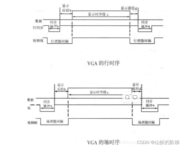
VESA Synchronization pulses are required for both line timing and field timing defined in (Sync a)、 Show the trailing edge (Back porch b)、 Show time series (Display interval c) And display frontiers (Front porch d) Four parts .【 The synchronous pulse is required to be a negative pulse 】
The blanking interval is the display leading edge of the previous sequence + Synchronization pulse of this sequence + The display trailing edge of this sequence .
Each row has a negative row synchronization pulse (Sync a), Is the end flag of the data line , It's also the start of the next line . After the synchronization pulse is the display trailing edge (Back porch b), In the display sequence segment (Display interval c) When the display is on ,RGB Data drives every pixel on a line , This shows a line . At the end of the line, display the leading edge (Front porch d). In the display time period (Display interval c) If there is no image projected onto the screen, the blanking signal is inserted . Synchronous pulse (Sync a)、 Show the trailing edge (Back porch b) And display frontiers (Front porch d) Are within the line blanking interval (Horizontal Blanking Interval), When the blanking is effective ,RGB Invalid signal , The screen doesn't show data
VGA_HS( Line synchronization ): In a cycle ,VGA_HS The low level time of is 96 individual VGA_CLK Signal period , High level time is 704 individual VGA_CLK Signal period .VGA The data signal of is in VGA_HS High level of the first 49 individual VGA_CLK The signal period begins to be valid , All the way to VGA_HS High level of the first 688 individual VGA_CLK Signal period .
among ,96 individual Hsync Pulse low level :Sync_pulse = 96;704 Period Hsync The high level of is divided into :Front Porch= 16 cycle , and BackFront Porch =48 cycle , remainder 704-16-48=640 This is the valid data period of one row ( One pixel per pixel cycle )
VGA_VS( Field synchronization ): In a cycle ,VGA_VS The low level time of is 2 individual VGA_HS Signal period , High level time is 523 individual VGA_HS Signal period .VGA The data signal of is in VGA_VS High level of the first 34 individual VGA_HS The signal period begins to be valid , Continue until the high level 513 individual VGA_HS Signal period .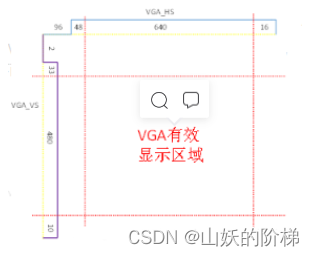
5.VGA Clock calculation
about 640* [email protected] That is, the resolution of one frame of image is 640* 480, Per second 60 Frequency frame refresh , Then the number of all pixels transmitted in one frame is 800* 525( Pay attention to the resolution 640* 480 It refers to the resolution of effective display data , Full resolution is required for calculation ), namely
VGA_CLK=HS_total×VS_total×FPS.
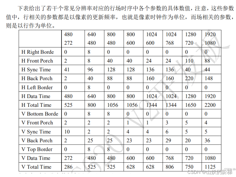
6. Different resolutions VGA Parameters
Two 、 Display the color bar
1. Color principle
Sanji ⾊ It means through other means ⾊ Mixing ⽆ I can't get it “ basic ⾊” because ⼈ Of ⾁ The eye has perception red 、 green 、 Blue has three different colors ⾊ Pyramidal cells , therefore ⾊ Color space can usually be divided into three basic types ⾊ To express . This is a ⾊ The most basic principle of metrics , namely Sanji ⾊ principle . Three bases ⾊ Is mutual independence ⽴ Of , whatever ⼀ Seed base ⾊ Can not have the other two kinds of face ⾊ synthesis . Red, green and blue are three bases ⾊, These three faces ⾊ Synthetic face ⾊ The scope is the most ⼴ extensive . our RGB The signal is really three basic ⾊ Luck ⽤, Assign different values to these three signals , It's different when mixed ⾊ The color .
Design RGB Signal time , You can R The signal 、G Signals and B Signal independence ⽴ Assignment , Finally, connect to the end ⼝ On , It can also be direct ⽤RGB treat as ⼀ An overall signal ,RGB The signal is making ⽤ At the time of the There are three common formats for bit width :
- RGB_8,R:G:B = 3:3:2, namely RGB332 RGB_16,
- R:G:B = 5:6:5, namely RGB565
- RGB_24,R:G:B = 8:8:8, namely RGB888
2. Color bar output
Parameters are defined
`define vga_640_480 //`define vga_800_600

`ifdef vga_640_480 `define  h_right_border  8
    `define h_front_porch 8 `define  h_sync_time     96
    `define h_back_porch 40 `define  h_left_border   8
    `define h_data_time 640 `define  h_total_time    800

    `define v_bottom_border 8 `define  v_front_porch   2
    `define v_sync_time 2 `define  v_back_porch    25
    `define v_top_border 8 `define  v_data_time     480
    `define v_total_time 525 `elsif vga_1280_720
    `define h_right_border 0 `define  h_front_porch   110
    `define h_sync_time 40 `define  h_back_porch    220
    `define h_left_border 0 `define  h_data_time     1280
    `define h_total_time 1650 `define  v_bottom_border 0
    `define v_front_porch 5 `define  v_sync_time     5
    `define v_back_porch 20 `define  v_top_border    0
    `define v_data_time 720 `define  v_total_time    750
`elsif vga_1920_1080 `define  h_right_border  0
    `define h_front_porch 88 `define  h_sync_time     44
    `define h_back_porch 148 `define  h_left_border   0
    `define h_data_time 1920 `define  h_total_time    2200

    `define v_bottom_border 0 `define  v_front_porch   4
    `define v_sync_time 5 `define  v_back_porch    36
    `define v_top_border 0 `define  v_data_time     1080
    `define v_total_time 1125 `elsif vga_800_600
    `define h_right_border 0 `define  h_front_porch   40
    `define h_sync_time 128 `define  h_back_porch    88
    `define h_left_border 0 `define  h_data_time     800
    `define h_total_time 1056 `define  v_bottom_border 0
    `define v_front_porch 1 `define  v_sync_time     4
    `define v_back_porch 23 `define  v_top_border    0
    `define v_data_time 600 `define  v_total_time    628
`endif
VGA drive
`include "vga_par.v" module vga_ctrl( input wire clk ,//VGA The clock 25.2MHz input wire rst_n ,// Reset signal  input wire [23:00] data_dis ,// output reg [10:00] h_addr ,// Data valid display area row address  output reg [10:00] v_addr ,// Data valid display area field address  output reg hsync ,// output reg vsync ,// output reg [07:00] vga_r ,// output reg [07:00] vga_g ,// output reg [07:00] vga_b , // output reg vga_blk ,//vga Blanking signal  output wire vga_clk // ); // Parameters are defined  parameter h_sync_sta = 1, h_sync_sto = `h_sync_time,
               h_data_sta = `h_left_border + `h_front_porch +`h_sync_time, h_data_sto = `h_left_border  + `h_front_porch +`h_sync_time + `h_data_time, v_sync_sta = 1, v_sync_sto = `v_sync_time,
               v_data_sta = `v_top_border + `v_back_porch +`v_sync_time, v_data_sto = `v_top_border + `v_back_porch +`v_sync_time + `v_data_time; // Signal definition  reg [11:0] cnt_h_addr;// Row address counter  wire add_h_addr; wire end_h_addr; reg [11:0] cnt_v_addr;// Field address counter  wire add_v_addr; wire end_v_addr; // always @(posedge clk or negedge rst_n) begin if (!rst_n) begin cnt_h_addr <= 12'd0; end else if (add_h_addr) begin if (end_h_addr) begin cnt_h_addr <= 12'd0; end else begin cnt_h_addr <= cnt_h_addr + 12'd1; end end else begin cnt_h_addr <= cnt_h_addr; end end assign add_h_addr = 1'b1; assign end_h_addr = add_h_addr && cnt_h_addr >= `h_total_time - 1;

    always @(posedge clk or negedge rst_n) begin
        if (!rst_n) begin
            cnt_v_addr <= 12'd0; end else if (add_v_addr) begin if (end_v_addr) begin cnt_v_addr <= 12'd0;
            end
            else begin
                cnt_v_addr <= cnt_v_addr + 12'd1; end end else begin cnt_v_addr <= cnt_v_addr; end end assign add_v_addr = end_h_addr; assign end_v_addr = add_v_addr && cnt_v_addr >= `v_total_time - 1; // Field synchronization signal  always @(posedge clk or negedge rst_n) begin if (!rst_n) begin hsync <= 1'b1;
        end
        else if(cnt_h_addr == h_sync_sta -1) begin
            hsync <= 1'd0; end else if(cnt_h_addr == h_sync_sto -1)begin hsync <= 1'b1;
        end
        else begin
            hsync <= hsync;
        end
    end

    always @(posedge clk or negedge rst_n) begin
        if (!rst_n) begin
            vsync <= 1'b1; end else if(cnt_v_addr == v_sync_sta -1) begin vsync <= 1'd0;
        end
        else if(cnt_v_addr == v_sync_sto -1)begin
            vsync <= 1'b1; end else begin vsync <= vsync; end end assign vga_clk = ~clk; // Data valid display area definition  always @(posedge clk or negedge rst_n) begin if (!rst_n) begin h_addr <= 11'd0;
        end
        else if((cnt_h_addr >= h_data_sta ) && (cnt_h_addr <= h_data_sto) )begin h_addr <= cnt_h_addr - h_data_sta; end else begin h_addr <= 11'd0; end end always @(posedge clk or negedge rst_n) begin if (!rst_n) begin v_addr <= 11'd0; end else if((cnt_v_addr >= v_data_sta ) && (cnt_v_addr <= v_data_sto))begin
            v_addr <= cnt_v_addr - v_data_sta;
        end
        else begin
            v_addr <= 11'd0; end end // Display the data  always @(posedge clk or negedge rst_n) begin if (!rst_n) begin vga_r <= 8'd0;
            vga_g   <= 8'd0; vga_b <= 8'd0;
            vga_blk <= 1'b0; end else if((cnt_h_addr >= h_data_sta -1 ) && (cnt_h_addr <= h_data_sto -1 ) && (cnt_v_addr >= v_data_sta -1 ) && (cnt_v_addr <= v_data_sto -1 ))begin vga_r <= data_dis[23-:08]; vga_g <= data_dis[15-:08]; vga_b <= data_dis[07-:08]; vga_blk <= 1'b1;

        end
        else begin
            vga_r <= 8'd0; vga_g <= 8'd0;
            vga_b <= 8'd0; vga_blk <= 1'b0;
        end
    end

    //assign sync = 1'b0;
endmodule
Top level documents
module vga_top(
    input   wire                    clk         ,
    input   wire                    rst_n       ,
    output  wire                    hsync       ,//
    output  wire                    vsync       ,
    output  wire  [07:00]           vga_r       ,//
    output  wire  [07:00]           vga_g       ,//
    output  wire  [07:00]           vga_b       ,//
    output  wire                    vga_blk     ,
    output  wire                    vga_clk      //
);

wire [10:00]          h_addr      ;
wire [10:00]          v_addr      ;
wire [23:00]          data_dis    ;


pll1	pll1_inst (
	.areset ( ~rst_n ),
	.inclk0 ( clk ),
	.c0 ( vga_clk ),
	.c1 ( clk1 )
	);

data_gen u_data_gen(
    .clk         (vga_clk  ),//VGA The clock 25.2MHz
    .rst_n       (rst_n    ),// Reset signal
    .h_addr      (h_addr   ),// Data valid display area row address
    .v_addr      (v_addr   ),// Data valid display area field address
    .vga_blk     (vga_blk  ),
    .data_dis    (data_dis )//
);

vga_ctrl u_vga_ctrl(
    .clk         (vga_clk  ),//VGA The clock 25.2MHz
    .rst_n       (rst_n    ),// Reset signal
    .data_dis    (data_dis ),//
    .h_addr      (h_addr   ),// Data valid display area row address
    .v_addr      (v_addr   ),// Data valid display area field address
    .hsync       (hsync    ),//
    .vsync       (vsync    ),//
    .vga_r       (vga_r    ),//
    .vga_g       (vga_g    ),//
    .vga_b       (vga_b    ), //
    .vga_blk     (vga_blk  )
);
endmodule
Color bar output
module data_gen(
    input   wire                  clk         ,//VGA The clock 25.2MHz
    input   wire                  rst_n       ,// Reset signal
    input   wire [10:00]          h_addr      ,// Data valid display area row address
    input   wire [10:00]          v_addr      ,// Data valid display area field address
    input   wire                  vga_blk     ,

    output  reg [23:00]           data_dis     //
);
    parameter
        BLACK       = 24'H000000, RED = 24'HFF0000,
        GREEN       = 24'H00FF00, BLUE = 24'H0000FF,
        YELLOW      = 24'HFFFF00, SKY_BULE = 24'H00FFFF,
        PURPLE      = 24'HFF00FF, GRAY = 24'HC0C0C0,
        WHITE       = 24'HFFFFFF;
    parameter
        h_vld       = 640,
        v_vld       = 480,

        pic_w       =272,
        pic_h       =16,

        x_start     =   (h_vld - pic_w >>1 ) -1,
        y_start     =   (v_vld - pic_h >>1 ) -1;
    reg [10:00] pix_x,pix_y;
    reg [ 271:0 ] char_line[ 15:0 ];   //272*16
    reg [15:00]     rom_address;

// Color bar
always @(posedge clk or negedge rst_n) begin
        if (!rst_n) begin
            data_dis <= WHITE;
        end
        else  begin
            case (h_addr)
                0       :   data_dis <= BLACK   ;
                80      :   data_dis <= RED     ;
                160     :   data_dis <= GREEN   ;
                240     :   data_dis <= BLUE    ;
                320     :   data_dis <= YELLOW  ;
                400     :   data_dis <= SKY_BULE;
                480     :   data_dis <= PURPLE  ;
                560     :   data_dis <= GRAY    ;
                default :   data_dis <= data_dis;
            endcase
        end
    end
endmodule
To configure USB-Blaster drive :https://blog.csdn.net/ssj925319/article/details/115333028
Pin configuration 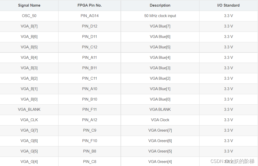

Burn operation results 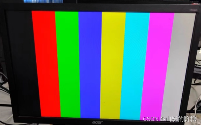
Change the resolution to 800*600 Change the clock to 40MHz: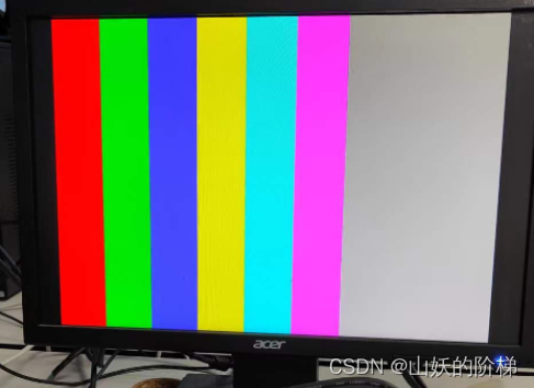
3、 ... and 、VGA Show characters
module VGA_test(
OSC_50,     // primary CLK2_50 Clock signal
VGA_CLK,    //VGA Self clock
VGA_HS,     // Line sync
VGA_VS,     // Field synchronization signal
VGA_BLANK,  // Composite blank signal control signal    When BLANK It is the blanking level of analog video output at low level , At that moment, from R9~R0,G9~G0,B9~B0 All data entered is ignored
VGA_SYNC,   // In accordance with the synchronization control signal        Both line timing and field timing should generate synchronization pulses
VGA_R,      //VGA green
VGA_B,      //VGA Blue
VGA_G);     //VGA green
 input OSC_50;     // External clock signal CLK2_50
 output VGA_CLK,VGA_HS,VGA_VS,VGA_BLANK,VGA_SYNC;
 output [7:0] VGA_R,VGA_B,VGA_G;
 parameter H_FRONT = 16;     // The leading edge signal period of line synchronization is long
 parameter H_SYNC = 96;      // The period of line synchronization signal is long
 parameter H_BACK = 48;      // The signal period of the trailing edge of line synchronization is long
 parameter H_ACT = 640;      // The line display cycle is long
 parameter H_BLANK = H_FRONT+H_SYNC+H_BACK;        // The total period of line blank signal is long
 parameter H_TOTAL = H_FRONT+H_SYNC+H_BACK+H_ACT;  // The total line cycle is long and time-consuming
 parameter V_FRONT = 11;     // The signal period at the front of field synchronization is long
 parameter V_SYNC = 2;       // The period of field synchronization signal is long
 parameter V_BACK = 31;      // The signal period at the trailing edge of field synchronization is long
 parameter V_ACT = 480;      // Long field display period
 parameter V_BLANK = V_FRONT+V_SYNC+V_BACK;        // The total period of field blank signal is long
 parameter V_TOTAL = V_FRONT+V_SYNC+V_BACK+V_ACT;  // The total period of the field is long and time-consuming
 reg [10:0] H_Cont;        // Line cycle counter
 reg [10:0] V_Cont;        // Field period counter
 wire [7:0] VGA_R;         //VGA Red control line
 wire [7:0] VGA_G;         //VGA Green control line
 wire [7:0] VGA_B;         //VGA Blue control line
 reg VGA_HS;
 reg VGA_VS;
 reg [10:0] X;             // The number of pixels in the current line
 reg [10:0] Y;             // Which line of the current field
 reg CLK_25;
 [email protected](posedge OSC_50)
    begin
      CLK_25=~CLK_25;         // The clock
    end
    assign VGA_SYNC = 1'b0; // Synchronization signal low level  assign VGA_BLANK = ~((H_Cont<H_BLANK)||(V_Cont<V_BLANK)); // When the row counter is less than the total length of the row blank or the field counter is less than the total length of the field blank , Blank signal low level  assign VGA_CLK = ~CLK_to_DAC; //VGA The clock is equal to CLK_25 Take the opposite  assign CLK_to_DAC = CLK_25; [email protected](posedge CLK_to_DAC) begin if(H_Cont<H_TOTAL) // If the row counter is less than the total row time  H_Cont<=H_Cont+1'b1;      // Row counter +1
        else H_Cont<=0;              // Otherwise, the line counter is cleared
        if(H_Cont==H_FRONT-1)        // If the row counter is equal to the blank time at the leading edge of the row -1
            VGA_HS<=1'b0; // The line synchronization signal is set to 0 if(H_Cont==H_FRONT+H_SYNC-1) // If the row counter is equal to the row leading edge + Line synchronization -1 VGA_HS<=1'b1;             // The line synchronization signal is set to 1
        if(H_Cont>=H_BLANK)          // If the row counter is greater than or equal to the total length of row blank
            X<=H_Cont-H_BLANK;        //X Equal to the row counter - Total length of blank lines    (X Is the number of pixels in the current line )
        else X<=0;                   // otherwise X by 0
    end
 [email protected](posedge VGA_HS)
    begin
        if(V_Cont<V_TOTAL)           // If the field counter is less than the total row time
            V_Cont<=V_Cont+1'b1; // Field counter +1 else V_Cont<=0; // Otherwise, the field counter is cleared  if(V_Cont==V_FRONT-1) // If the field counter is equal to the field leading edge blank time -1 VGA_VS<=1'b0;             // The field synchronization signal is set to 0
        if(V_Cont==V_FRONT+V_SYNC-1) // If the field counter is equal to the leading edge of the row + Field synchronization -1
            VGA_VS<=1'b1; // The field synchronization signal is set to 1 if(V_Cont>=V_BLANK) // If the field counter is greater than or equal to the total time of field blank  Y<=V_Cont-V_BLANK; //Y Equal to the field counter - Total duration of field blank  (Y For the line number of the current field ) else Y<=0; // otherwise Y by 0 end reg valid_yr; [email protected](posedge CLK_to_DAC) if(V_Cont == 10'd32)         // Field counter =32 when
        valid_yr<=1'b1; // Line input activates  else if(V_Cont==10'd512)     // Field counter =512 when
        valid_yr<=1'b0; // Line input freeze  wire valid_y=valid_yr; // attachment  reg valid_r; [email protected](posedge CLK_to_DAC) if((H_Cont == 10'd32)&&valid_y)     // Row counter =32 when
        valid_r<=1'b1; // Pixel input active  else if((H_Cont==10'd512)&&valid_y) // Row counter =512 when
        valid_r<=1'b0; // Pixel input is frozen  wire valid = valid_r; // attachment  wire[10:0] x_dis; // Pixel display control signal  wire[10:0] y_dis; // The line shows the control signal  assign x_dis=X; // attachment X assign y_dis=Y; // attachment Y parameter // Dot matrix font : Every line char_lineXX Is a line displayed , common 272 Column  char_line00=272'hFFFFFFFFFFFFFFFFFFFFFFFFFFFFFFFFFFFFFFFFFFFFFFFFFFFFFFFFFFFFFFFFFFFF,  // The first 1 That's ok
    char_line01=272'h00000000000000000000000000000000000000000000000000000000000000000000, // The first 2 That's ok  char_line02=272'h00400C0000000000000000000000000000C008000000000000000000000000000000,  // The first 3 That's ok
    char_line03=272'h00700E0000000180000000000000000000E00C0000000000000000800180000000C0, // The first 4 That's ok  char_line04=272'h00600C00000003C0000000000000000000C01C0000000000000000FFFF80000001E0,  // The first 5 That's ok
    char_line05=272'h00600C3003FFFC000000000000000080008018000000000000800080018003FFFE00, // The first 6 That's ok  char_line06=272'h1FFFFFF8000180007FFE7FF003C80380008018007C1F03C803800080018000000000,  // The first 7 That's ok
    char_line07=272'h00600C0000018000180E18180E3803800104301018040E3803800080018000000000, // The first 8 That's ok  char_line08=272'h00600C00000180001802180C080803800FFE30381804080803800080018000000000,  // The first 9 That's ok
    char_line09=272'h00600C000001800018031806180802800C0C7FF818041808028000FFFF8000000000, // The first 10 That's ok  char_line0a=272'h007FFC000001800018011806300406C00C0C60300C08300406C00080018000000000,  // The first 11 That's ok
    char_line0b=272'h00600C000001800018001806300404C00C0CC0300C08300404C00080018000000018, // The first 12 That's ok  char_line0c=272'h00600C000001801018081806200004C00C0C80300C08200004C0008001800000003C,  // The first 13 That's ok
    char_line0d=272'h007FFC000001803818081806600004C00C0D00300C08600004C0008001803FFFFFFE, // The first 14 That's ok  char_line0e=272'h00600C003FFFFFFC1818180C60000C600C0D4030061060000C6000FFFF8000018000,  // The first 15 That's ok
    char_line0f=272'h00600C10000180001FF81818600008600C0E20300610600008600080010000018000, // The first 16 That's ok  char_line10=272'h00600C380001800018181FF0600008600C0C10300610600008600008200000418000,  // The first 17 That's ok
    char_line11=272'h3FFFFFFC0001800018081800600008600FFC1830073060000860000C382000718800, // The first 18 That's ok  char_line12=272'h003208000001800018081800603F1FF00C0C18300320603F1FF0080C307000E18600,  // The first 19 That's ok
    char_line13=272'h00618C000001800018001800600C10300C0C0C300320600C10300C0C307000C18300, // The first 20 That's ok  char_line14=272'h00C106000001800018001800600C10300C0C08300320600C1030060C30C001818180,  // The first 21 That's ok
    char_line15=272'h018101C00001800018001800300C10300C0C003001C0300C1030030C30C0038180C0, // The first 22 That's ok  char_line16=272'h030104FC0001800018001800300C30300C0C003001C0300C3030038C318003018060,  // The first 23 That's ok
    char_line17=272'h0C010E380001800018001800180C20180C0C003001C0180C2018018C330006018070, // The first 24 That's ok  char_line18=272'h187FF0000001800018001800180C20180C0C003001C0180C2018018C36000C018038,  // The first 25 That's ok
    char_line19=272'h6001000000018000180018000C1060180C0C003000800C106018008C380018018038, // The first 26 That's ok  char_line1a=272'h00010000000180007E007E0003E0F83E0C0C0030008003E0F83E000C301010018010,  // The first 27 That's ok
    char_line1b=272'h00010000003F800000000000000000000FFC0C60000000000000000C303820738000, // The first 28 That's ok  char_line1c=272'h00010060000F800000000000000000000C0C03E00000000000001FFFFFFC001F8000,  // The first 29 That's ok
    char_line1d=272'h1FFFFFF00007000000000000000000000C0801C00000000000000000000000070000, // The first 30 That's ok  char_line1e=272'h00000000000000000000000000000000000000800000000000000000000000020000,  // The first 31 That's ok
    char_line1f=272'h00000000000000000000000000000000000000000000000000000000000000000000; // The first 32 That's ok  reg[8:0] char_bit; [email protected](posedge CLK_to_DAC) if(X==10'd144)char_bit<=9'd272; // When displayed to 144 Pixel ready to start outputting image data  else if(X>10'd144&&X<10'd416) // Left margin screen 144 Pixels to 416 When the pixel  416=144+272( The width of the image ) char_bit<=char_bit-1'b1;       // Output image information upside down
        reg[29:0] vga_rgb;                // Define color cache
    [email protected](posedge CLK_to_DAC)
        if(X>10'd144&&X<10'd416)    //X Controls the horizontal display boundary of the image : Left margin to the left of the screen 144 Pixels    The right boundary is away from the left boundary of the screen 416 Pixels
            begin case(Y)            //Y Controls the vertical display boundary of the image : From the top of the screen 160 Pixels begin to display the first row of data
                10'd160: if(char_line00[char_bit])vga_rgb<=30'b1111111111_0000000000_0000000000;  // If the row has data   The color is red
                else vga_rgb<=30'b0000000000_0000000000_0000000000; // Otherwise black  10'd162:
                if(char_line01[char_bit])vga_rgb<=30'b1111111111_0000000000_0000000000; else vga_rgb<=30'b0000000000_0000000000_0000000000;
                10'd163: if(char_line02[char_bit])vga_rgb<=30'b1111111111_0000000000_0000000000;
                else vga_rgb<=30'b0000000000_0000000000_0000000000; 10'd164:
                if(char_line03[char_bit])vga_rgb<=30'b1111111111_0000000000_0000000000; else vga_rgb<=30'b0000000000_0000000000_0000000000;
                10'd165: if(char_line04[char_bit])vga_rgb<=30'b1111111111_0000000000_0000000000;
                else vga_rgb<=30'b0000000000_0000000000_0000000000; 10'd166:
                if(char_line05[char_bit])vga_rgb<=30'b1111111111_0000000000_0000000000; else vga_rgb<=30'b0000000000_0000000000_0000000000;
                10'd167: if(char_line06[char_bit])vga_rgb<=30'b1111111111_0000000000_0000000000;
                else vga_rgb<=30'b0000000000_0000000000_0000000000; 10'd168:
                if(char_line07[char_bit])vga_rgb<=30'b1111111111_0000000000_0000000000; else vga_rgb<=30'b0000000000_0000000000_0000000000;
                10'd169: if(char_line08[char_bit])vga_rgb<=30'b1111111111_0000000000_0000000000;
                else vga_rgb<=30'b0000000000_0000000000_0000000000; 10'd170:
                if(char_line09[char_bit])vga_rgb<=30'b1111111111_0000000000_0000000000; else vga_rgb<=30'b0000000000_0000000000_0000000000;
                10'd171: if(char_line0a[char_bit])vga_rgb<=30'b1111111111_0000000000_0000000000;
                else vga_rgb<=30'b0000000000_0000000000_0000000000; 10'd172:
                if(char_line0b[char_bit])vga_rgb<=30'b1111111111_0000000000_0000000000; else vga_rgb<=30'b0000000000_0000000000_0000000000;
                10'd173: if(char_line0c[char_bit])vga_rgb<=30'b1111111111_0000000000_0000000000;
                else vga_rgb<=30'b0000000000_0000000000_0000000000; 10'd174:
                if(char_line0d[char_bit])vga_rgb<=30'b1111111111_0000000000_0000000000; else vga_rgb<=30'b0000000000_0000000000_0000000000;
                10'd175: if(char_line0e[char_bit])vga_rgb<=30'b1111111111_0000000000_0000000000;
                else vga_rgb<=30'b0000000000_0000000000_0000000000; 10'd176:
                if(char_line0f[char_bit])vga_rgb<=30'b1111111111_0000000000_0000000000; else vga_rgb<=30'b0000000000_0000000000_0000000000;
                10'd177: if(char_line10[char_bit])vga_rgb<=30'b1111111111_0000000000_0000000000;
                else vga_rgb<=30'b0000000000_0000000000_0000000000; 10'd178:
                if(char_line11[char_bit])vga_rgb<=30'b1111111111_0000000000_0000000000; else vga_rgb<=30'b0000000000_0000000000_0000000000;
                10'd179: if(char_line12[char_bit])vga_rgb<=30'b1111111111_0000000000_0000000000;
                else vga_rgb<=30'b0000000000_0000000000_0000000000; 10'd180:
                if(char_line13[char_bit])vga_rgb<=30'b1111111111_0000000000_0000000000; else vga_rgb<=30'b0000000000_0000000000_0000000000;
                10'd181: if(char_line14[char_bit])vga_rgb<=30'b1111111111_0000000000_0000000000;
                else vga_rgb<=30'b0000000000_0000000000_0000000000; 10'd182:
                if(char_line15[char_bit])vga_rgb<=30'b1111111111_0000000000_0000000000; else vga_rgb<=30'b0000000000_0000000000_0000000000;
                10'd183: if(char_line16[char_bit])vga_rgb<=30'b1111111111_0000000000_0000000000;
                else vga_rgb<=30'b0000000000_0000000000_0000000000; 10'd184:
                if(char_line17[char_bit])vga_rgb<=30'b1111111111_0000000000_0000000000; else vga_rgb<=30'b0000000000_0000000000_0000000000;
                10'd185: if(char_line18[char_bit])vga_rgb<=30'b1111111111_0000000000_0000000000;
                else vga_rgb<=30'b0000000000_0000000000_0000000000; 10'd186:
                if(char_line19[char_bit])vga_rgb<=30'b1111111111_0000000000_0000000000; else vga_rgb<=30'b0000000000_0000000000_0000000000;
                10'd187: if(char_line1a[char_bit])vga_rgb<=30'b1111111111_0000000000_0000000000;
                else vga_rgb<=30'b0000000000_0000000000_0000000000; 10'd188:
                if(char_line1b[char_bit])vga_rgb<=30'b1111111111_0000000000_0000000000; else vga_rgb<=30'b0000000000_0000000000_0000000000;
                10'd189: if(char_line1c[char_bit])vga_rgb<=30'b1111111111_0000000000_0000000000;
                else vga_rgb<=30'b0000000000_0000000000_0000000000; 10'd190:
                if(char_line1d[char_bit])vga_rgb<=30'b1111111111_0000000000_0000000000; else vga_rgb<=30'b0000000000_0000000000_0000000000;
                10'd191: if(char_line1e[char_bit])vga_rgb<=30'b1111111111_0000000000_0000000000;
                else vga_rgb<=30'b0000000000_0000000000_0000000000; 10'd192:
                if(char_line1f[char_bit])vga_rgb<=30'b1111111111_0000000000_0000000000; else vga_rgb<=30'b0000000000_0000000000_0000000000;
                default:vga_rgb<=30'h0000000000; // Default color black  endcase end else vga_rgb<=30'h000000000;             // Otherwise black
    assign VGA_R=vga_rgb[23:16];
    assign VGA_G=vga_rgb[15:8];
    assign VGA_B=vga_rgb[7:0];
endmodule
Burn run 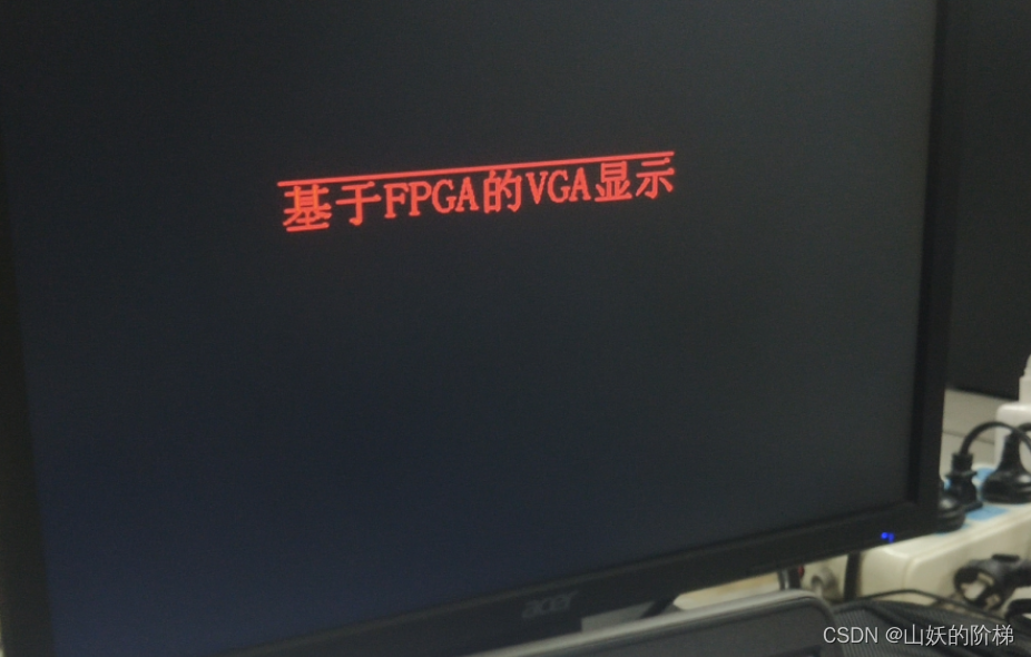
Four 、 Custom character display
// Initialize display text
[email protected]( posedge clk or negedge rst_n ) begin
    if ( !rst_n ) begin
      char_line[ 0 ]  = 272'h010010010000000000000000000000000000000000000000000000000000; char_line[ 1 ] = 272'h010021000804000000000000000000000000000000000000000000000000;
      char_line[ 2 ]  = 272'h028011fc7f78000000000000000000000000000000000000000000000000; char_line[ 3 ] = 272'h04401200004018003c000800380018007e0018001800180008003c007e00;
      char_line[ 4 ]  = 272'h082085f82240240042003800440024004200240024002400380042004200; char_line[ 5 ] = 272'h101041081440400042000800420042000400420040004200080042000400;
      char_line[ 6 ]  = 272'h2fe84948ff7e400002000800420042000400420040004200080042000400; char_line[ 7 ] = 272'hc106092808485c000400080042004200080042005c004200080002000800;
      char_line[ 8 ]  = 272'h010017fe0848620018000800460042000800420062004200080004000800; char_line[ 9 ] = 272'h3ff811087f484200040008003a0042001000420042004200080008001000;
      char_line[ 10 ] = 272'h0100e2480848420002000800020042001000420042004200080010001000; char_line[ 11 ] = 272'h111022282a48420042000800020042001000420042004200080020001000;
      char_line[ 12 ] = 272'h110823fc4948220042000800240024001000240022002400080042001000; char_line[ 13 ] = 272'h2104200888881c003c003e0018001800100018001c0018003e007e001000;
      char_line[ 14 ] = 272'h450420502888000000000000000000000000000000000000000000000000; char_line[ 15 ] = 272'h020000201108000000000000000000000000000000000000000000000000;
    end
end

always @(posedge clk or negedge rst_n) begin
    if (!rst_n) begin
        pix_x <= 11'd0; pix_y <= 11'd0;
    end
    else if ((h_addr >= x_start && h_addr < x_start +pic_w) &&(v_addr >= y_start && v_addr < y_start + pic_h)) begin
        pix_x <= h_addr - x_start;
        pix_y <= v_addr - y_start;
    end
    else begin
        pix_x <= 11'h7ff; pix_y <= 11'h7ff;
    end
end

always @(posedge clk or negedge rst_n) begin
        if (!rst_n) begin
            data_dis <= BLACK;
        end
        else if (pix_x != 11'h7FF && pix_y != 11'h7FF) begin
            if(char_line[pix_y][271 - pix_x]== 1'b1)begin
                data_dis <= WHITE;
            end
            else begin
                data_dis <= BLUE;
            end
        end
        else begin
        data_dis <= data_dis;
        end
end
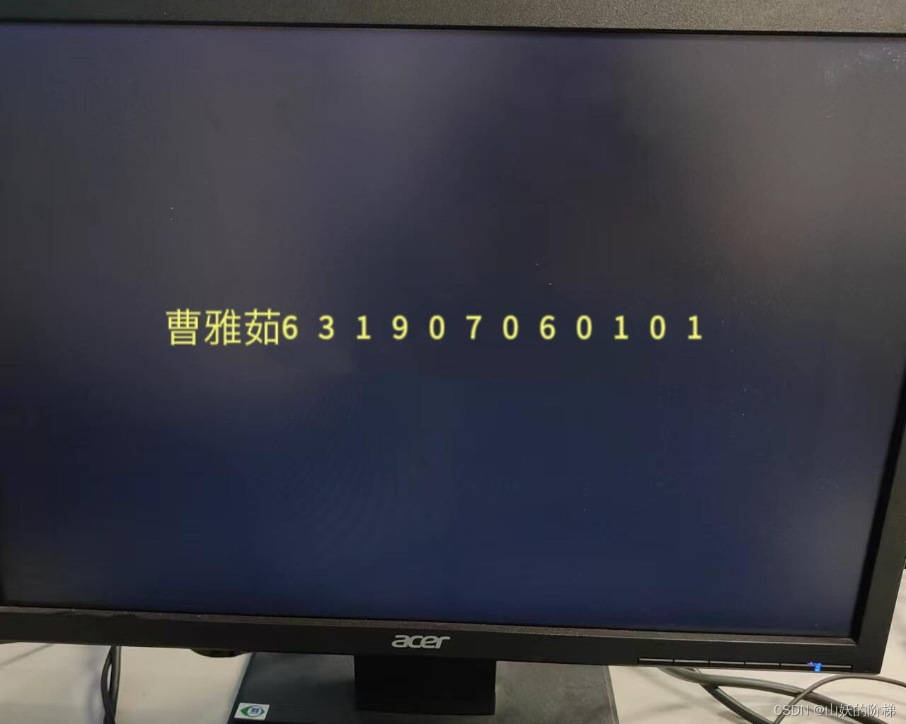
5、 ... and 、 summary
Reference link
https://blog.csdn.net/qq_61682562/article/details/125171347?spm=1001.2014.3001.5502
https://wenku.baidu.com/view/cea418180a12a21614791711cc7931b765ce7bb7.html
https://wenku.baidu.com/view/df4ad0ccadaad1f34693daef5ef7ba0d4a736dea.html
边栏推荐
- PowerPivot - DAX (function)
- A very good JVM interview question article (74 questions and answers)
- Find duplicate email addresses
- Rk3399 platform development series explanation (WiFi) 5.52. Introduction to WiFi framework composition
- 进程间通信之共享内存
- CTFshow--常用姿势
- ST表预处理时的数组证明
- Introduction to the extension implementation of SAP Spartacus checkout process
- 从“跑分神器”到数据平台,鲁大师开启演进之路
- 测试开发基础,教你做一个完整功能的Web平台之环境准备
猜你喜欢

话说SQLyog欺骗了我!

You don't know the complete collection of recruitment slang of Internet companies
深度聚类:将深度表示学习和聚类联合优化
cf:C. Column Swapping【排序 + 模拟】
Detailed explanation of platform device driver architecture in driver development
Jmeter自带函数不够用?不如自己动手开发一个

Jstack of JVM command: print thread snapshots in JVM
C note 13

Career experience feedback to novice programmers

A very good JVM interview question article (74 questions and answers)
随机推荐
Cloud acceleration helps you effectively solve attack problems!
Database notes 04
蚂蚁庄园安全头盔 7.8蚂蚁庄园答案
一名普通学生的大一总结【不知我等是愚是狂,唯知一路向前奔驰】
JVM command - jmap: export memory image file & memory usage
Sequential storage of stacks
Introduction to the extension implementation of SAP Spartacus checkout process
laravel 使用腾讯云 COS5全教程
Interview skills of software testing
Check point: the core element for enterprises to deploy zero trust network (ztna)
绕过open_basedir
[Shell]常用shell命令及测试判断语句总结
骑士战胜魔王(背包&dp)
解决pod install报错:ffi is an incompatible architecture
Detailed explanation of platform device driver architecture in driver development
Party A's requirements for those who have lost 800 yuan
Dc-7 target
Flask1.1.4 werkzeug1.0.1 source code analysis: start the process
ML之shap:基于adult人口普查收入二分类预测数据集(预测年收入是否超过50k)利用shap决策图结合LightGBM模型实现异常值检测案例之详细攻略
搞懂fastjson 对泛型的反序列化原理