当前位置:网站首页>Part III Verilog enterprise real topic of "Niuke brush Verilog"
Part III Verilog enterprise real topic of "Niuke brush Verilog"
2022-07-05 23:34:00 【Trip of Jie】
Preface
Previously brushed HDLbits The title above , Click the link to view the detailed notes :verilog practice :hdlbits The website series is over !
Recently, I want to brush the title of Niuke , You can click the link to brush the questions with Xiaobian : Niu Ke brush questions
I don't know , If there is anything wrong in the text , You can communicate with each other in comments . The topic here is recommended to see the comment area of Niuke , One more word , Pay attention to accumulate your basic skills
Algorithm 、 Design patterns 、 Software etc.
Part I Verilog Quick start
- If you want to Introduction learning , You can click on the link :《 Niuke brush verilog》Part I Verilog Quick start
Part II Verilog Advanced challenges
- If you want to Advanced learning , You can click on the link :《 Niuke brush verilog》Part II Verilog Advanced challenges
Part III Verilog Enterprise truth
01 Zhe K
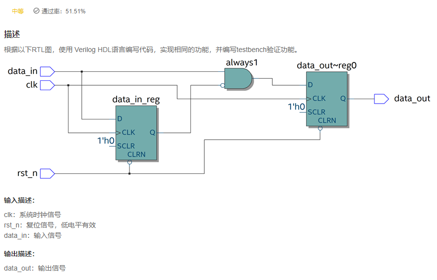
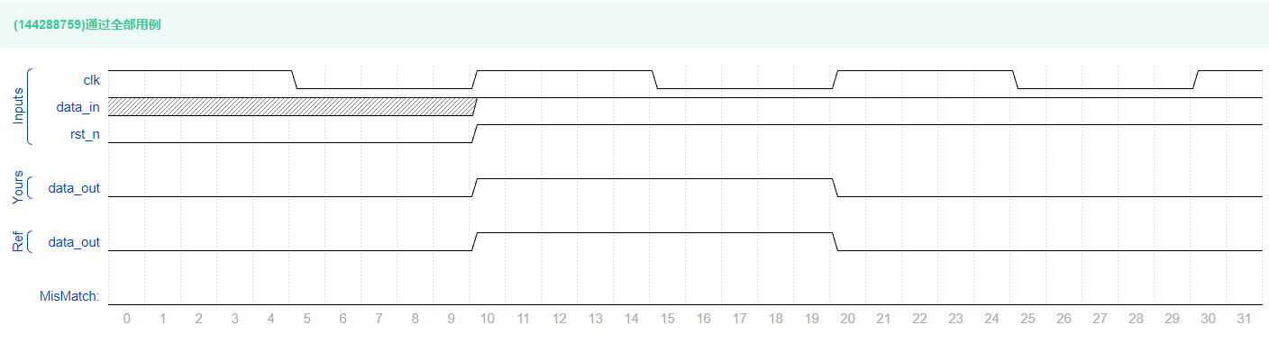
VL59 according to RTL Drawing compilation Verilog Program
answer
`timescale 1ns/1ns

module RTL(
	input clk,
	input rst_n,
	input data_in,
	output reg data_out
	);

    reg data_in_reg;
    [email protected](posedge clk or negedge rst_n) begin
        if(!rst_n)begin
           data_in_reg <= 'd0;
        end else begin
            data_in_reg <= data_in;
        end
    end

    assign always1 = data_in & ~data_in_reg;

    [email protected](posedge clk or negedge rst_n) begin
        if(!rst_n)begin
            data_out <= 'd0;
        end else begin
            data_out <= always1;
        end
    end
endmodule
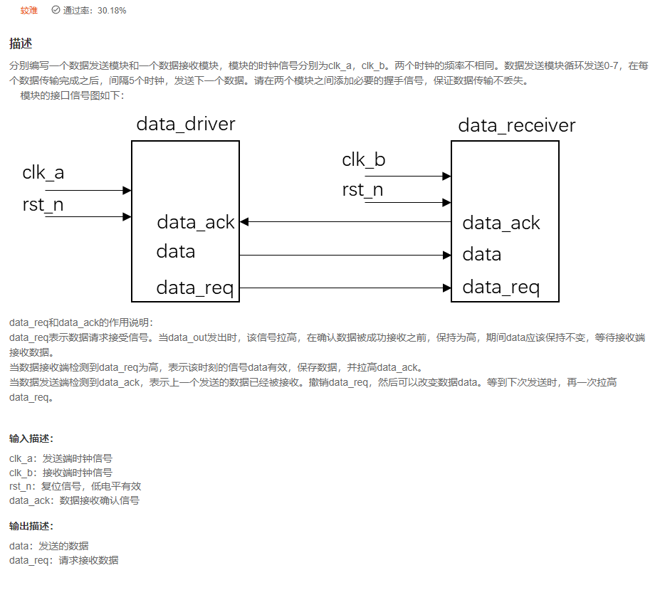
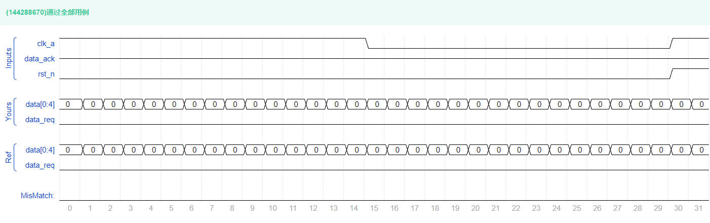
VL60 Use handshake signal to realize cross clock domain data transmission
answer
`timescale 1ns/1ns

module data_driver(
	input clk_a,
	input rst_n,
	input data_ack,
	output reg [3:0]data,
	output reg data_req
	);

	reg data_ack_reg_1,data_ack_reg_2;
	always @ (posedge clk_a or negedge rst_n)
		if (!rst_n)
		begin
            {
    data_ack_reg_1,data_ack_reg_2} <= 'd0;
		end
		else
		begin
            {
    data_ack_reg_1,data_ack_reg_2} <= {
    data_ack,data_ack_reg_1};
		end

// wire flag = data_ack_reg_1 && !data_ack_reg_2;
    wire flag = {
    data_ack_reg_1,data_ack_reg_2} == 2'b10;

	always @ (posedge clk_a or negedge rst_n)
		if (!rst_n) begin
			data <= 0;
		end
		else if(flag)begin
// if(data == 'd7)
// data <= 'd0;
			data <= data+1;
		end
        else begin
			data <= data;
		end


    reg [2:0] cnt;
// At the same time data_ack After it works , Start counting five clocks , Then send new data , That is to pull up again data_req.
	always @ (posedge clk_a or negedge rst_n)
		if (!rst_n)
			cnt <= 0;
        else if (flag)
			cnt <= 0;
		else if (data_req)
			cnt <= cnt;
		else
			cnt <= cnt+1;

	always @ (posedge clk_a or negedge rst_n)
		if (!rst_n)
			data_req <= 0;
		else if (cnt == 3'd4)
			data_req <= 1'b1;
		else if (flag)
			data_req <= 1'b0;
		else
			data_req <= data_req;

endmodule

module data_receiver(
	input clk_b,
	input rst_n,
	output reg data_ack,
	input [3:0]data,
	input data_req
	);

	reg [3:0]data_in_reg;
	reg data_req_reg_1, data_req_reg_2;

	always @ (posedge clk_b or negedge rst_n)
		if (!rst_n)begin
            {
    data_req_reg_1, data_req_reg_2} <= 'd0;
		end
		else begin
            {
    data_req_reg_1, data_req_reg_2} <= {
    data_req, data_req_reg_1};
		end

    wire flag = {
    data_req_reg_1, data_req_reg_2} == 2'b10;

	always @ (posedge clk_b or negedge rst_n)
		if (!rst_n)
			data_ack <= 0;
		else if (flag)
			data_ack <= 1;
		else  data_ack <=0 ;

	always @ (posedge clk_b or negedge rst_n)
		if (!rst_n)
			data_in_reg <= 0;
		else if (flag)
			data_in_reg <= data;
		else  data_in_reg <= data_in_reg ;

endmodule
replay
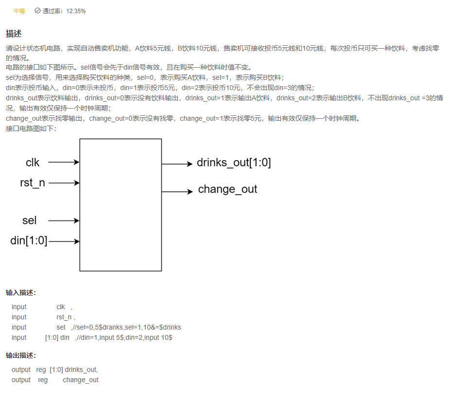
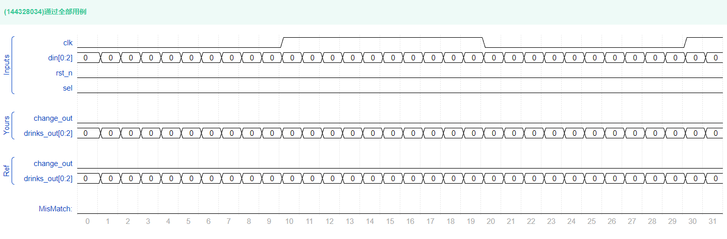
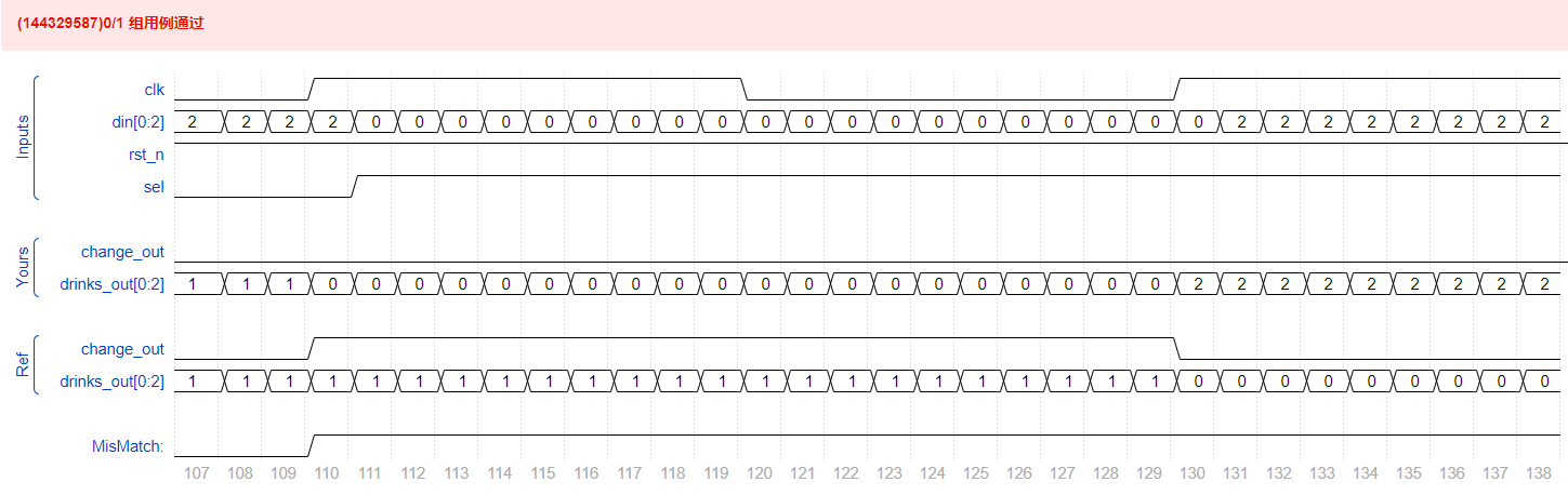
VL61 Vending machine
answer
`timescale 1ns/1ns

module sale(
   input                clk   ,
   input                rst_n ,
   input                sel   ,//sel=0,5$dranks,sel=1,10&=$drinks
   input          [1:0] din   ,//din=1,input 5$,din=2,input 10$

   output   reg  [1:0] drinks_out,//drinks_out=1,output 5$ drinks,drinks_out=2,output 10$ drinks
   output	reg        change_out
);

    reg [2:0] c_state,n_state;
    parameter IDLE = 3'd0;
    parameter S1 = 3'd1;//5 Yuan to buy 5 Yuan beverage
    parameter S2 = 3'd2;//10 Yuan to buy 5 Yuan drinks 5 block
    parameter S3 = 3'd3;//5 Ten yuan for drinks
    parameter S4 = 3'd4;// added 5 block , Not looking for
    parameter S5 = 3'd5;// added 10 block , look for 5 block


[email protected](posedge clk or negedge rst_n)
    if(!rst_n)
    c_state<=IDLE;
    else
    c_state <= n_state;


[email protected](*)
    if(sel== 1'b0)begin
    case(c_state)
        IDLE:begin
            case(din)
                2'b00: n_state <= IDLE;
                2'b01:  n_state <= S1;
                2'b10: n_state <= S2;
            endcase
          end
        S1:begin
            case(din)
                2'b00: n_state <= IDLE;
                2'b01:  n_state <= S1;
                2'b10: n_state <= S2;
            endcase
          end
        S2:begin
            case(din)
                2'b00: n_state <= IDLE;
                2'b01:  n_state <= S1;
                2'b10: n_state <= S2;
            endcase
          end
        S3:begin
            case(din)
                2'b00: n_state <= IDLE;
                2'b01:  n_state <= IDLE;
                2'b10: n_state <= IDLE;
            endcase
          end
        S4:begin
            case(din)
                2'b00: n_state <= IDLE;
                2'b01:  n_state <= IDLE;
                2'b10: n_state <= IDLE;
            endcase
          end
        S5:begin
            case(din)
                2'b00: n_state <= IDLE;
                2'b01:  n_state <= IDLE;
                2'b10: n_state <= IDLE;
            endcase
          end
    endcase
    end
else begin
    case(c_state)
        IDLE:begin
            case(din)
                2'b00: n_state <= IDLE;
                2'b01:  n_state <= S3;
                2'b10: n_state <= S4;
            endcase
        end
        S1:begin
            case(din)
                2'b00: n_state <= IDLE;
                2'b01:  n_state <= IDLE;
                2'b10: n_state <= IDLE;
            endcase
        end
        S2:begin
            case(din)
                2'b00: n_state <= IDLE;
                2'b01:  n_state <= IDLE;
                2'b10: n_state <= IDLE;
            endcase
        end
        S3:begin
            case(din)
                2'b00: n_state <= S3;
                2'b01:  n_state <= S4;
                2'b10: n_state <= S5;
            endcase
        end
        S4:begin
            case(din)
                2'b00: n_state <= IDLE;
                2'b01:  n_state <= S3;
                2'b10: n_state <= S4;
            endcase
        end
        S5:begin
            case(din)
                2'b00: n_state <= IDLE;
                2'b01:  n_state <= S3;
                2'b10: n_state <= S4;
            endcase
        end
    endcase
end

[email protected](*)
    if(!rst_n)begin
        drinks_out <= 0;
        change_out <=0;
    end
    else begin
        case(c_state)
            IDLE:begin
                drinks_out <= 0;
                change_out <=0;
            end
            S1:begin
                drinks_out <= 2'd1;
                change_out <=1'd0;
            end
            S2:begin
                drinks_out <= 2'd1;
                change_out <=1'd1;
            end
            S3:begin
                drinks_out <= 0;
                change_out <=0;
            end
            S4:begin
                drinks_out <=2'd2;
                change_out <=0;
            end
            S5:begin
                drinks_out <= 2'd2;
                change_out <=1'd1;
            end
        endcase
    end
endmodule
replay
- Give a failed code , It can be modified .
`timescale 1ns/1ns

module sale(
   input                clk   ,
   input                rst_n ,
   input                sel   ,//sel=0,5$dranks,sel=1,10&=$drinks
   input          [1:0] din   ,//din=1,input 5$,din=2,input 10$

   output   reg  [1:0] drinks_out,//drinks_out=1,output 5$ drinks,drinks_out=2,output 10$ drinks
   output	reg        change_out
);

    parameter IDLE = 2'd0;//0 element
    parameter S1   = 2'd1;//5 element
    parameter S2   = 2'd2;//10 element
    parameter S3   = 2'd3;//15 element

    // The first paragraph
    reg [1:0] cur_state, next_state;
    [email protected](posedge clk or negedge rst_n) begin
        if(!rst_n) begin
            cur_state <= IDLE;
        end
        else begin
            cur_state <= next_state;
        end
    end

    // The second paragraph
    [email protected](*) begin
        case(cur_state)
            IDLE:begin
                if(din == 2'b01)
                    next_state = S1;
                else if(din == 2'b10)
                    next_state = S2;
                else
                    next_state = next_state;
            end
            S1:begin
                if(sel == 0)// buy 5 yuan
                    next_state = IDLE;
                else if(din == 2'b01)
                    next_state = S2;
                else if(din == 2'b10)
                    next_state = S3;
                else
                    next_state = next_state;
            end
            S2:begin
                next_state = IDLE;
            end
            S3:begin
                next_state = IDLE;
            end
            default:    next_state = IDLE;
        endcase
    end


    // The third paragraph
    [email protected](posedge clk or negedge rst_n) begin
        if(!rst_n) begin
            {
    drinks_out,change_out} <= 3'b00_0;
        end
        else case(next_state)
            IDLE:begin
                {
    drinks_out,change_out} <= 3'b00_0;
            end
            S1:begin
                if(sel == 0)// buy 5 yuan
                    {
    drinks_out,change_out} <= 3'b01_0;
                else
                    {
    drinks_out,change_out} <= 3'b00_0;
            end
            S2:begin
                if(sel == 0)// buy 5 yuan
                    {
    drinks_out,change_out} <= 3'b01_1;
                else
                    {
    drinks_out,change_out} <= 3'b10_0;
            end
            S3:begin
                {
    drinks_out,change_out} <= 3'b10_1;
            end
            default:{
    drinks_out,change_out} <= 3'b00_0;
        endcase
    end

endmodule
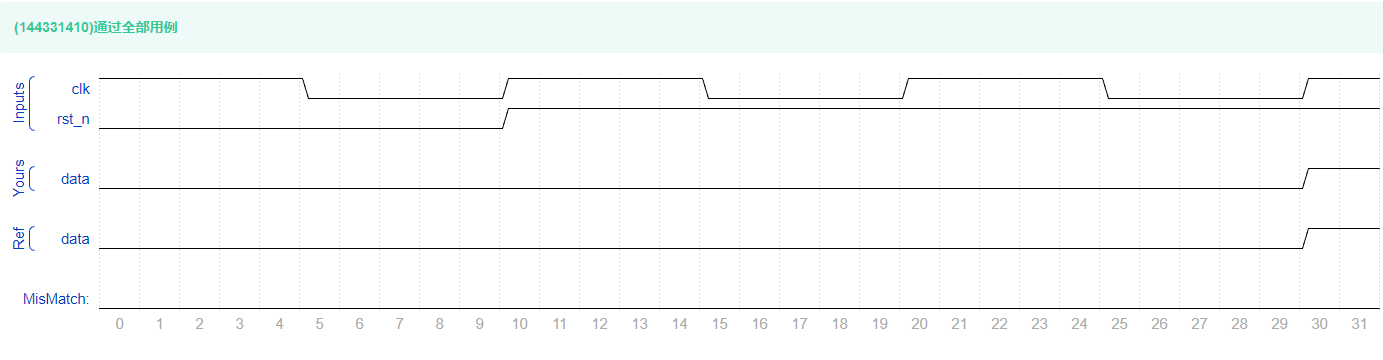
VL62 Sequence generator
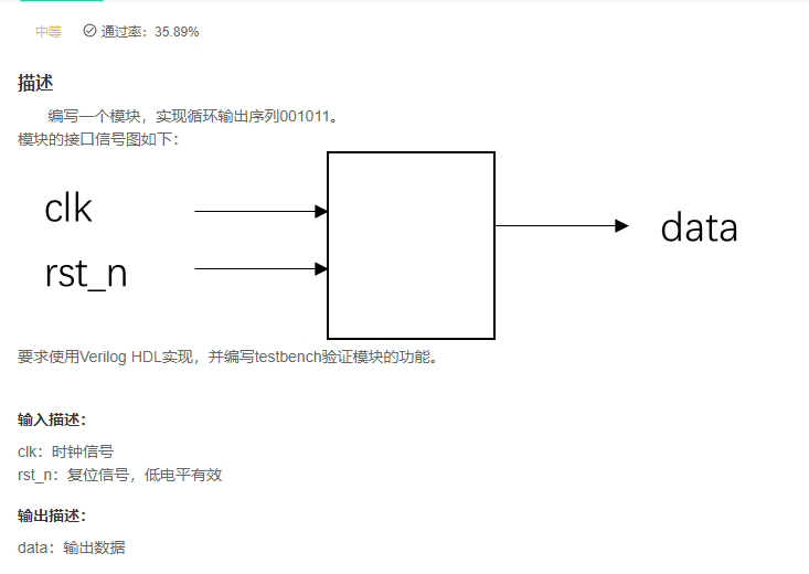
answer
`timescale 1ns/1ns

module sequence_generator(
	input clk,
	input rst_n,
	output reg data
	);

    reg [5:0] data_reg;
    [email protected](posedge clk or negedge rst_n) begin
        if(!rst_n)
            data_reg <= 6'b001011;
        else
            data_reg <= {
    data_reg, data_reg[5]};
    end


    [email protected](posedge clk or negedge rst_n) begin
        if(!rst_n)
            data <= 1'b0;
        else
            data <= data_reg[5];
    end

endmodule
replay
02 Hua W
VL63 Parallel string conversion
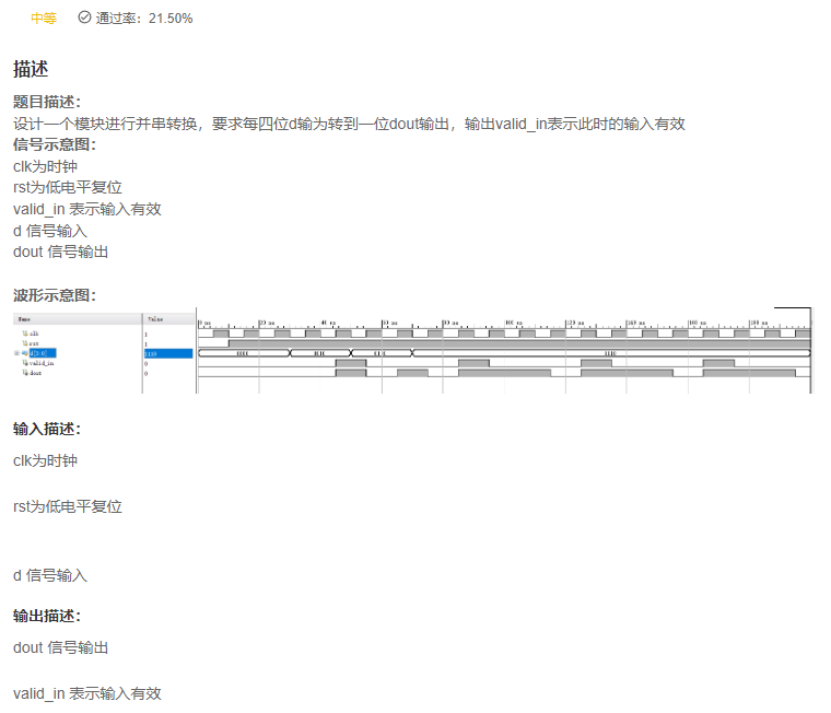
answer
`timescale 1ns/1ns


module huawei5(
	input wire clk  ,
	input wire rst  ,
	input wire [3:0]d ,
	output wire valid_in ,
	output wire dout
	);

//*************code***********//

reg [3:0] data = 'd0;
reg [1:0]cnt;// Count
reg valid;

assign dout = data[3];//data The highest bit of is connected to the output line
assign valid_in =valid;

always @(posedge clk or negedge rst) begin
    if(!rst)begin
        data<= 'd0;
        cnt <= 'd0;
        valid <= 'd0;
    end
    else  begin
		if (cnt == 'd3) begin
			data <= d;//d Is in cnt It will be given when it is cleared data The uploaded
			cnt <= 'd0;
			valid <= 1;
		end
		else begin
			cnt <= cnt + 'd1;
			valid <= 0;
			data  <= {
    data[2:0],data[3]};// Cyclic shift to the left
		end
    end
end
//*************code***********//

endmodule
replay
- Related topic recommendation 《 Niuke brush verilog》Part II Verilog Advanced challenges There is VL30 Data series to parallel circuit
- The core of this topic is , Read the title :
Shift output from high position,4 individual bit For a cycle . The concrete way is : Move the high position to the low position by cyclic left shift , Then use the characteristics of mutual deposit , Make the highest register output .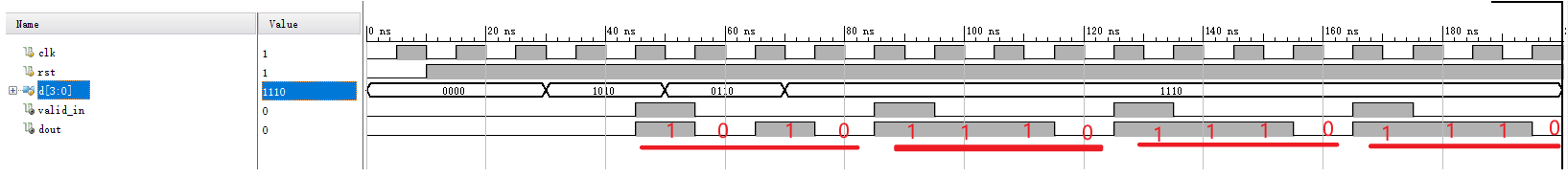
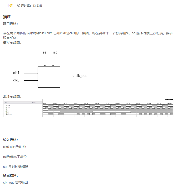
VL64 Clock switching
answer
`timescale 1ns/1ns

module huawei6(
	input    wire    clk0    ,
	input    wire    clk1    ,
	input    wire    rst     ,
	input    wire    sel     ,
	output   wire    clk_out
);
    reg q0, q1;

    [email protected](negedge clk1 or negedge rst)
        if(!rst)
            q0 <= 0;
        else
            q0 <= ~sel & ~q1;

    [email protected](negedge clk0 or negedge rst)
        if(!rst)
            q1 <= 0;
         else
            q1 <= sel & ~q0;

    assign clk_out = (q0 & clk0) | (q1 & clk1);

endmodule
replay
- What's that? ?
VL65 State machine and clock frequency division
Title Description : Use state machine to realize clock frequency division , It is required to divide the clock by four , Duty ratio 0.25
Signal schematic diagram :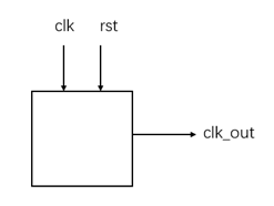
clk Is the clock
rst Reset for low level
clk_out Signal output
Ps The solution of this problem is based on 1000 State transition of , Not in this state , The compiler may report an error, but it does not affect .
Waveform diagram :
Input description :
clk Is the clock
rst Reset for low level
Output description :
clk_out Signal output
answer
`timescale 1ns/1ns

module huawei7(
	input wire clk  ,
	input wire rst  ,
	output reg clk_out
);

//*************code***********//
    parameter S0 = 'd0;
    parameter S1 = 'd1;
    parameter S2 = 'd2;
    parameter S3 = 'd3;

    reg [1:0] state;

    [email protected](posedge clk or negedge rst)
        if(!rst)
            state <= S0;
        else
            case(state)
                S0:state <= S1;
                S1:state <= S2;
                S2:state <= S3;
                S3:state <= S0;
            endcase
    [email protected](*)
        if(state == S1)
            clk_out <= 'd1;
        else
            clk_out <= 'd0;
//*************code***********//
endmodule

replay
- The above state machine is a regular cycle , If the state condition is a single hot code , We
Whether shift can also be usedGet status . - The following answer is wrong , You can see that .
`timescale 1ns/1ns

module huawei7(
	input wire clk  ,
	input wire rst  ,
	output reg clk_out
);

//*************code***********//
    parameter S0 = 4'b0001;
    parameter S1 = 4'b0010;
    parameter S2 = 4'b0100;
    parameter S3 = 4'b1000;

    reg [3:0] state;

    [email protected](posedge clk or negedge rst)
        if(!rst)
            state <= S0;
        else
            state <= state << 1;

    [email protected](*)
        if(state == S1)
            clk_out <= 'd1;
        else
            clk_out <= 'd0;
//*************code***********//
endmodule
- What if you use a counter ?
`timescale 1ns/1ns

module huawei7(
	input wire clk  ,
	input wire rst  ,
	output reg clk_out
);

//*************code***********//
    reg [1:0] state;

    [email protected](posedge clk or negedge rst)
        if(!rst)
            state <= 'd0;
        else
            state <= state + 1'b1;

    [email protected](*)
        if(state == 2'b01)
            clk_out <= 'd1;
        else
            clk_out <= 'd0;
//*************code***********//
endmodule
VL66 Carry ahead adder
describe
Title Description :
Find two four bit data and write a four bit carry ahead adder , It is recommended to use sub modules
Tips : The bit formula of carry ahead adder is as follows
here ‘+’ ‘·’ The symbol is not ‘ Add ’ and ‘ ride ’, yes ‘ or ’ and ‘ And ’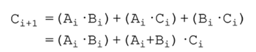
Waveform diagram :
Input description :
A B The input values
Output description :
OUT Add the results
answer
replay
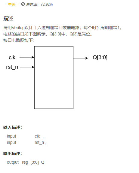
VL67 Hexadecimal counter
answer
`timescale 1ns/1ns

module counter_16(
   input                clk   ,
   input                rst_n ,

   output   reg  [3:0]  Q
);
    [email protected](posedge clk or negedge rst_n) begin
        if(!rst_n)
            Q <= 'd0;
        else
            Q <= Q + 1'b1;
    end
endmodule
replay
- Can you spread anything ?
VL68 Sync FIFO
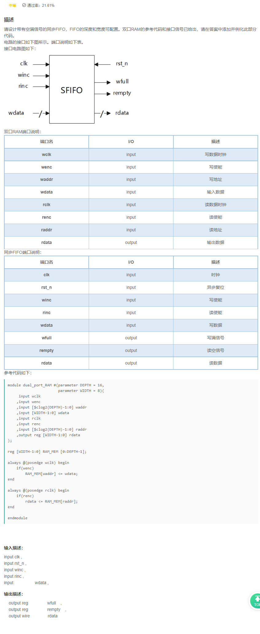
answer
`timescale 1ns/1ns

/**********************************RAM************************************/
module dual_port_RAM #(parameter DEPTH = 16,
					   parameter WIDTH = 8)(
	 input wclk
	,input wenc
	,input [$clog2(DEPTH)-1:0] waddr
	,input [WIDTH-1:0] wdata
	,input rclk
	,input renc
	,input [$clog2(DEPTH)-1:0] raddr
	,output reg [WIDTH-1:0] rdata
);

reg [WIDTH-1:0] RAM_MEM [0:DEPTH-1];

always @(posedge wclk) begin
	if(wenc)
		RAM_MEM[waddr] <= wdata;
end

always @(posedge rclk) begin
	if(renc)
		rdata <= RAM_MEM[raddr];
end

endmodule

/**********************************SFIFO************************************/
module sfifo#(
	parameter	WIDTH = 8,
	parameter 	DEPTH = 16
)(
	input 					clk		,
	input 					rst_n	,
	input 					winc	,
	input 			 		rinc	,
	input 		[WIDTH-1:0]	wdata	,

	output reg				wfull	,
	output reg				rempty	,
	output wire [WIDTH-1:0]	rdata
);
    localparam ADDR_WIDTH = $clog2(DEPTH) - 1 + 1;
    // Calculate the required bit width by depth , because fifo A flag bit is required at the highest bit to generate a full signal , Above again +1


    // The second step : to RAM Declare the missing port signal
    ///
    reg [ADDR_WIDTH:0] waddr,raddr;// Write the address , Read the address
    wire wenc,renc;// Write enable signal , Read enable signal


    // The third step : Write address operation , When to write
    ///
    [email protected](posedge clk or negedge rst_n) begin
        if(!rst_n) begin
            waddr <= 'd0;
        end
        else begin
            if(wenc) begin
                waddr <= waddr + 1'b1;
            end
            else begin
                waddr <= waddr;
            end
        end
    end

    assign wenc  = winc && ~wfull;// Write enable signal


    // Step four : Read address operation , When to read
    ///
    [email protected](posedge clk or negedge rst_n) begin
        if(!rst_n) begin
            raddr <= 'd0;
        end
        else begin
            if(renc) begin
                raddr <= raddr + 1'b1;
            end
            else begin
                raddr <= raddr;
            end
        end
    end

    assign renc  = rinc && ~rempty;// Read enable signal


    // Step five : Generate empty full signal
    ///
    [email protected](posedge clk or negedge rst_n) begin
        if(!rst_n) begin
            wfull <= 'd0;
            rempty <= 'd0;
        end
        else begin
            wfull <= ((waddr[ADDR_WIDTH] != raddr[ADDR_WIDTH]) && (waddr[ADDR_WIDTH-1:0] == raddr[ADDR_WIDTH-1:0]));
            rempty <= raddr == waddr;
        end
    end


    // First step : Instantiated double port RAM
    ///
    dual_port_RAM
    #(
        .DEPTH(DEPTH)
       ,.WIDTH(WIDTH)
     )
    dual_port_RAM_inst
    (
         .wclk  (clk     )
        ,.wenc  (wenc     )
        ,.waddr (waddr   )       // Depth pair 2 Take the logarithm , Get the bit width of the address .
        ,.wdata (wdata   )       // Data writing
        ,.rclk  (clk    )
        ,.renc  (renc    )
        ,.raddr (raddr   )       // Depth pair 2 Take the logarithm , Get the bit width of the address .
        ,.rdata (rdata   )	    // Data output
    );


endmodule
replay
- 《 Niuke brush verilog》Part II Verilog Advanced challenges There is synchronization in fifo And asynchronous fifo, This topic is completely consistent .
03 DJ
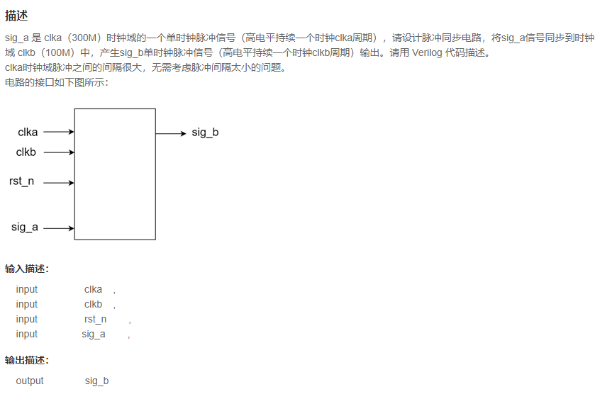
VL69 Pulse synchronizer ( Fast to slow )
answer
replay
VL70 Sequence detector (Moore type )
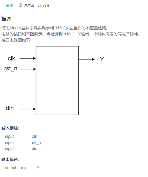
answer
`timescale 1ns/1ns

module det_moore(
   input                clk   ,
   input                rst_n ,
   input                din   ,

   output	reg         Y
);
    reg [3:0] din_reg;
    [email protected](posedge clk or negedge rst_n)
        if(!rst_n)
            din_reg <= 'd0;
        else
            din_reg <= {
    din_reg,din};

    [email protected](posedge clk or negedge rst_n)
        if(!rst_n)
            Y <= 'd0;
        else
            Y <= din_reg == 4'b1101;

endmodule
replay
- 《 Niuke brush verilog》Part II Verilog Advanced challenges Many topics in , Xiaobian uses this method .
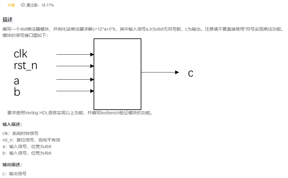
VL71 Multiplication and bit operation
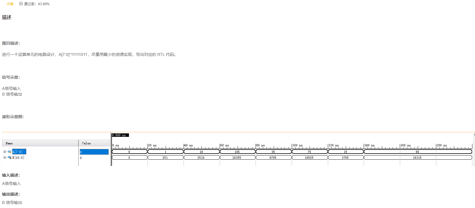
answer
replay
04 A in
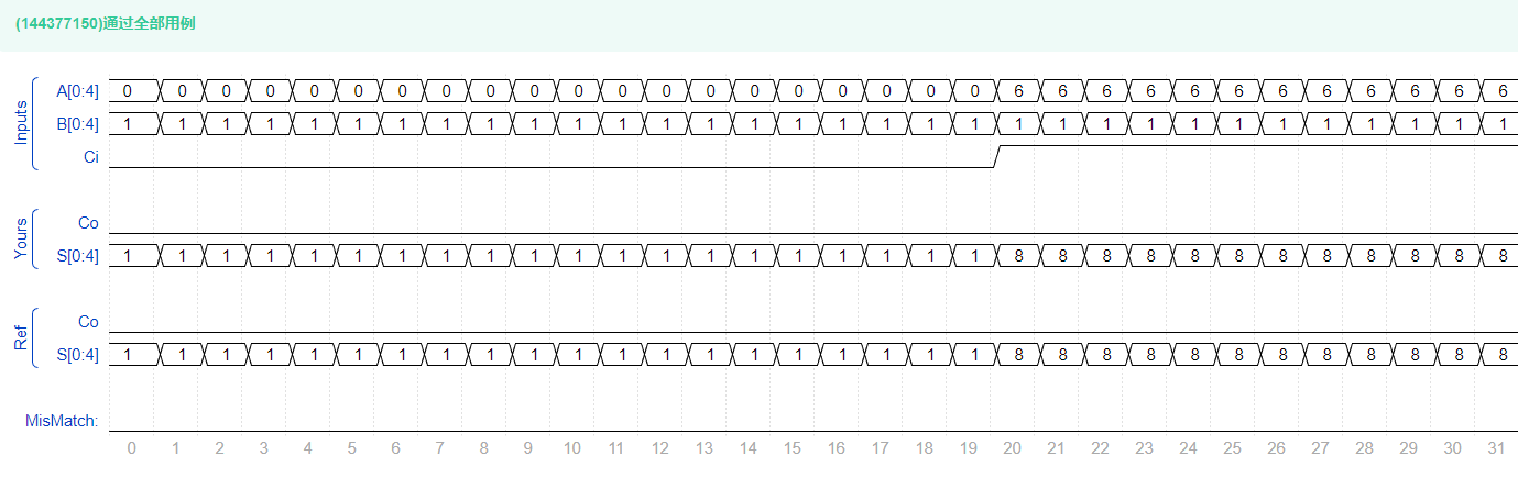
VL72 Full adder
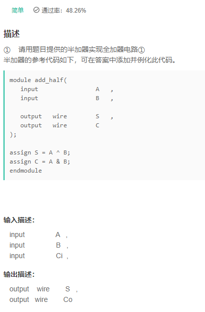
answer
`timescale 1ns/1ns

module add_half(
   input                A   ,
   input                B   ,

   output	wire        S   ,
   output   wire        C
);

assign S = A ^ B;
assign C = A & B;
endmodule

/***************************************************************/
module add_full(
   input                A   ,
   input                B   ,
   input                Ci  ,

   output	wire        S   ,
   output   wire        Co
);
    wire [1:0] s,c;
    add_half add_half_U1(A,B,s[0],c[0]);
    add_half add_half_u2(Ci,s[0],s[1],c[1]);
    assign S = s[1];
    assign Co = |c;
endmodule
replay

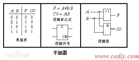
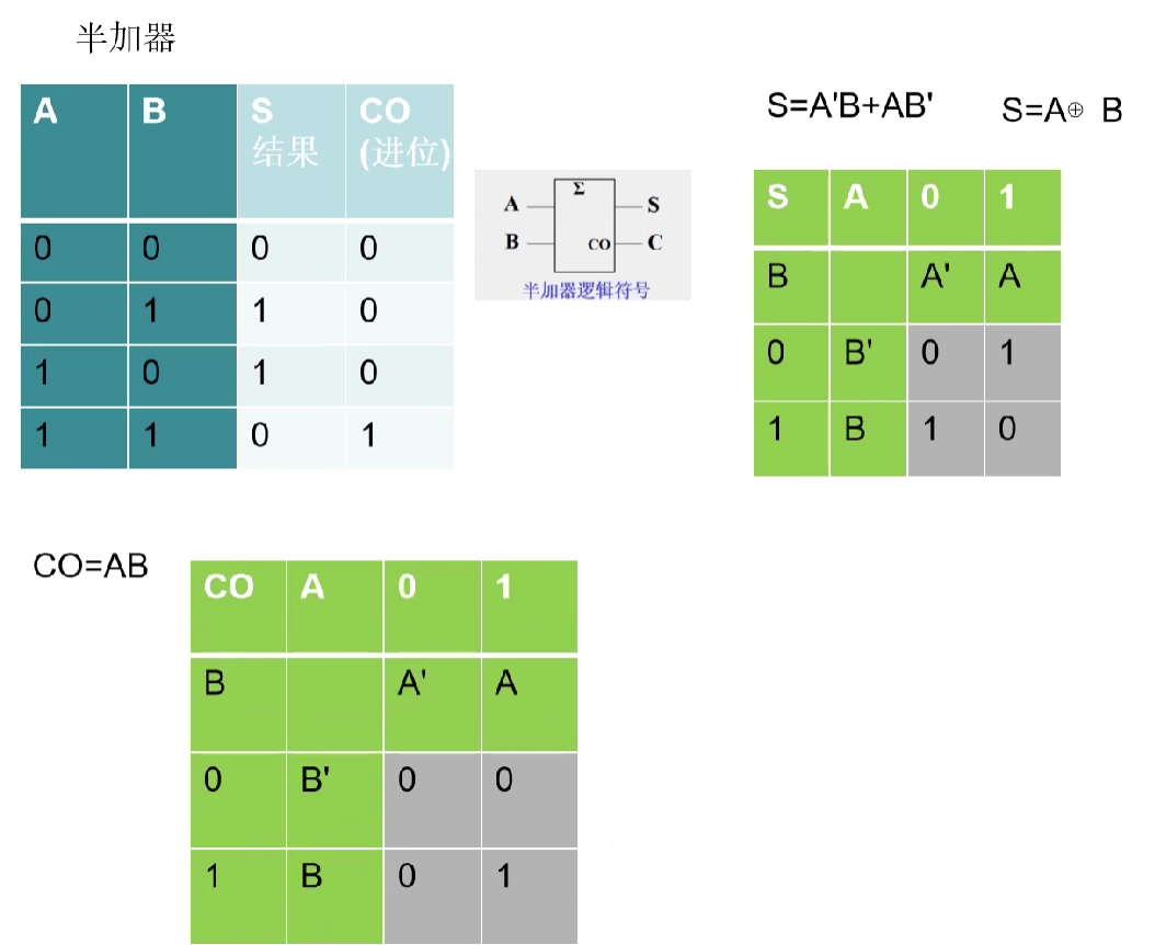
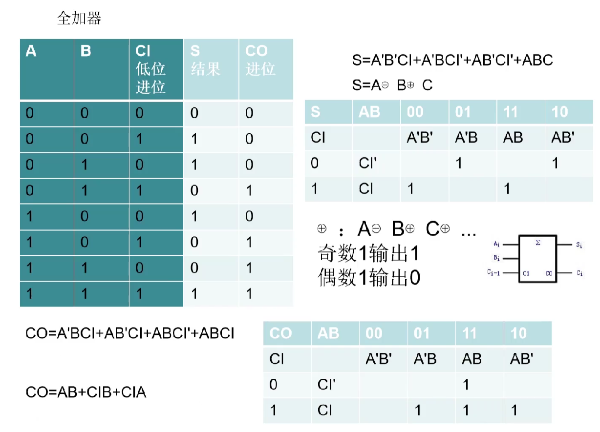
- At the beginning of study , Everyone should know ,
The half adder does not consider carry, But many people will definitely think , It seems that there is a carry , Like1'b1+1'b1 = 2'b10. Pay attention , The carry here refers to , stay1'b1+1'b1When considering the carry of the low order ? No, ! - The difference between half adder and full adder Mainly
The half adder has no input to receive carry, The full adder has a carry input , When adding two multi bit binary numbers , Except for the lowest bit , Each bit should consider the carry from the low bit , Half adder does not need to consider , Just consider the addition of two inputs . Half adderIt is a device that realizes the addition of two one bit binary numbers . It has two inputs ( Augend A And addends B) And output Y.Full adderIt is a combined circuit that adds two binary numbers and obtains the sum with a gate circuit , It's called a one bit full adder . A bit full adder can handle low carry , And output the standard addition carry . Multi bit full adders can be obtained by cascading multiple one bit full adders .
VL73 Serial carry adder
describe
② Please use full adder circuit ① Realize serial carry 4 Bit full adder circuit
1 The reference code of bit full adder is as follows :
module add_half(
   input                A   ,
   input                B   ,

   output	wire        S   ,
   output   wire        C
);

assign S = A ^ B;
assign C = A & B;
endmodule

/***************************************************************/
module add_full(
   input                A   ,
   input                B   ,
   input                Ci  ,

   output	wire        S   ,
   output   wire        Co
);

wire c_1;
wire c_2;
wire sum_1;

add_half add_half_1(
   .A   (A),
   .B   (B),

   .S   (sum_1),
   .C   (c_1)
);
add_half add_half_2(
   .A   (sum_1),
   .B   (Ci),

   .S   (S),
   .C   (c_2)
);

assign Co = c_1 | c_2;
endmodule
Input description :
input [3:0] A ,
input [3:0] B ,
input Ci ,
Output description :
output wire [3:0] S ,
output wire Co
answer
`timescale 1ns/1ns

module add_4(
   input         [3:0]  A   ,
   input         [3:0]  B   ,
   input                Ci  ,

   output	wire [3:0]  S   ,
   output   wire        Co
);

// assign {Co,S} = A + B + Ci;


    wire C[3:0];
    generate
        genvar i ;
        for(i=0;i<=3;i=i+1)
            begin: Li
                if(i==0) begin
                    add_full add_full_li(
                                         .A(A[i]),
                                         .B(B[i]),
                                         .Ci(Ci),

                                         .S(S[i]),
                                         .Co(C[i]));
                end
                else begin
                    add_full add_full_li(
                                         .A(A[i]),
                                         .B(B[i]),
                                         .Ci(C[i-1]),

                                         .S(S[i]),
                                         .Co(C[i]));
                end

            end
    endgenerate

    assign Co = C[3];
endmodule

module add_half(
   input                A   ,
   input                B   ,

   output	wire        S   ,
   output   wire        C
);

    assign S = A ^ B;
    assign C = A & B;
endmodule

/***************************************************************/
module add_full(
   input                A   ,
   input                B   ,
   input                Ci  ,

   output	wire        S   ,
   output   wire        Co
);

    wire c_1;
    wire c_2;
    wire sum_1;

    add_half add_half_1(
       .A   (A),
       .B   (B),

       .S   (sum_1),
       .C   (c_1)
    );
    add_half add_half_2(
       .A   (sum_1),
       .B   (Ci),

       .S   (S),
       .C   (c_2)
    );

    assign Co = c_1 | c_2;
endmodule
replay
- The full adder can also be realized without using the instantiated half adder
`timescale 1ns/1ns

module add_4(
   input         [3:0]  A   ,
   input         [3:0]  B   ,
   input                Ci  ,

   output	wire [3:0]  S   ,
   output   wire        Co
);

// assign {Co,S} = A + B + Ci;


    wire C[3:0];
    generate
        genvar i ;
        for(i=0;i<=3;i=i+1)
            begin: Li
                if(i==0) begin
                    add_full add_full_li(
                                         .A(A[i]),
                                         .B(B[i]),
                                         .Ci(Ci),

                                         .S(S[i]),
                                         .Co(C[i]));
                end
                else begin
                    add_full add_full_li(
                                         .A(A[i]),
                                         .B(B[i]),
                                         .Ci(C[i-1]),

                                         .S(S[i]),
                                         .Co(C[i]));
                end

            end
    endgenerate

    assign Co = C[3];
endmodule

module add_full(
    input A,
    input B,
    input Ci,

    output S,
    output Co
);

    assign S = A^B^Ci;
    assign Co = ((A^B)&Ci)|(A&B);
endmodule
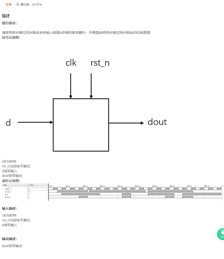
VL74 Asynchronous reset, synchronous release
answer
`timescale 1ns/1ns


module ali16(
input  wire clk,
input  wire rst_n,
input  wire d,
output reg dout
 );

reg rst0,rst1;
always @ (posedge clk or negedge rst_n) begin
	if (!rst_n) begin
        {
    rst0,rst1} <= 'd0;
	end
	else begin
        {
    rst0,rst1} <= {
    1'b1,rst0};
	end
end


always @ (posedge clk or negedge rst1)begin
    if(!rst1) begin
        dout <= 1'b0;
    end
    else begin
        dout <= d;
    end
end


endmodule
replay
- Asynchronous reset , Simultaneous release ?
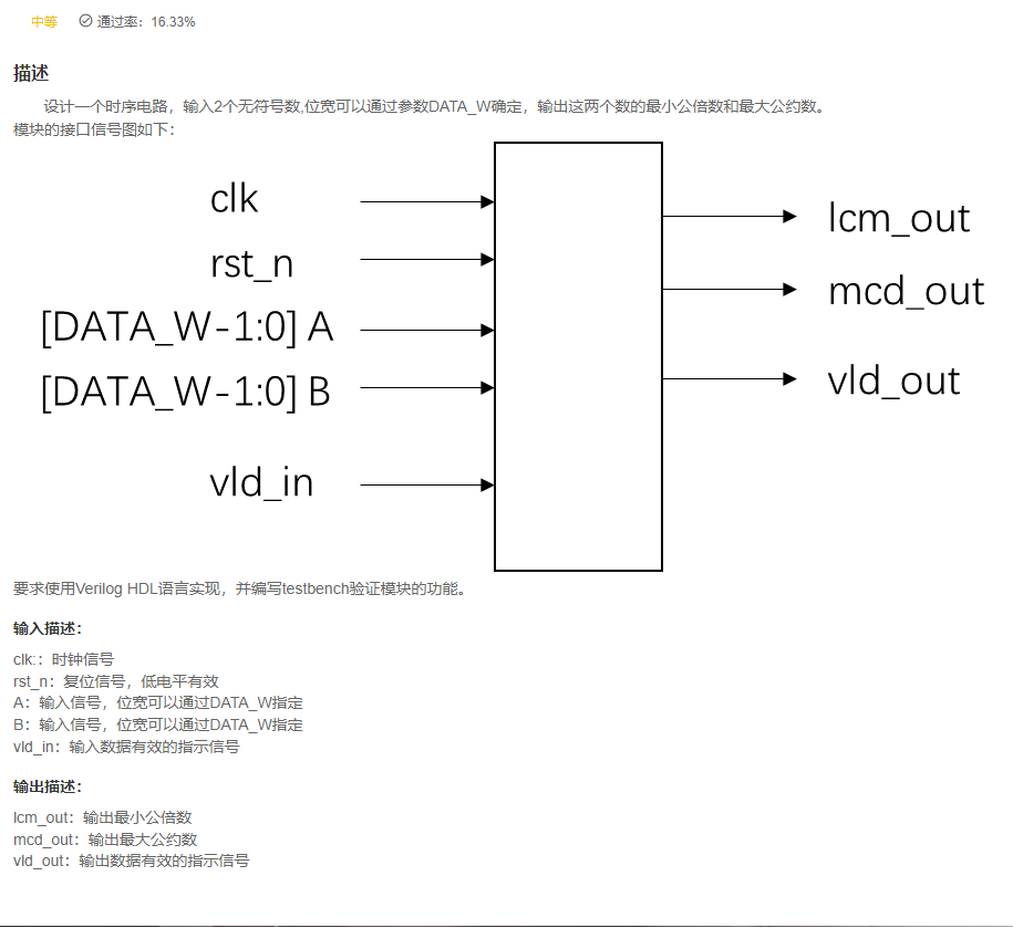
VL75 Find the least common multiple
answer
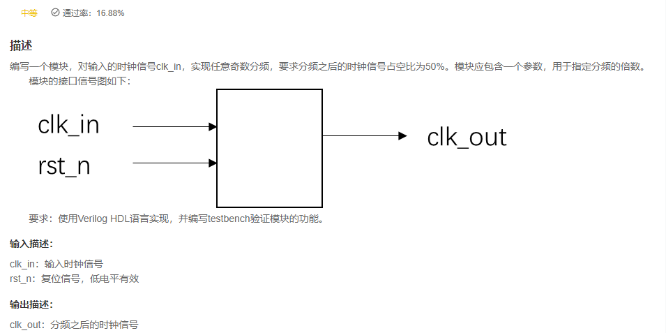
VL76 Any odd multiple clock frequency division
05 Z xing
VL77 Write multiplier algorithm expression
Postscript
Recommend related articles
- You can click the link to brush the questions with Xiaobian : Niu Ke brush questions
边栏推荐
- 保研笔记一 软件工程与计算卷二(1-7章)
- Solution to the packaging problem of asyncsocket long connecting rod
- Neural structured learning 4 antagonistic learning for image classification
- The interface of grafana tool displays an error, incluxdb error
- rsync远程同步
- orgchart. JS organization chart, presenting structural data in an elegant way
- Dynamic planning: robbing families and houses
- Scala concurrent programming (II) akka
- 424. The longest repeated character after replacement ●●
- asp.net弹出层实例
猜你喜欢
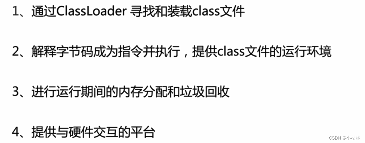
2: Chapter 1: understanding JVM specification 1: introduction to JVM;
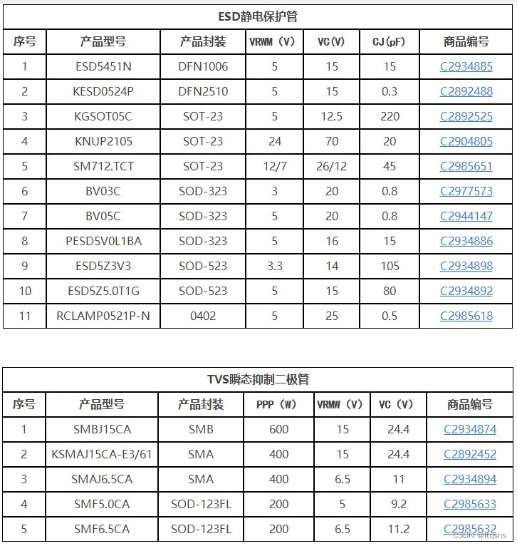
Technical specifications and model selection guidelines for TVs tubes and ESD tubes - recommended by jialichuang
Initial experience | purchase and activate typora software
Data analysis - Thinking foreshadowing

Rasa 3. X learning series -rasa x Community Edition (Free Edition) changes
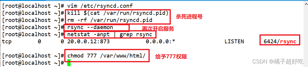
rsync远程同步

Non rigid / flexible point cloud ICP registration

How to design API return code (error code)?
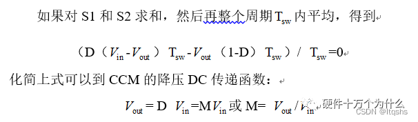
开关电源Buck电路CCM及DCM工作模式
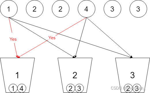
698. 划分为k个相等的子集 ●●
随机推荐
Golang code checking tool
Debian 10 installation configuration
MySQL delete uniqueness constraint unique
CIS基准测试工具kube-bench使用
14种神笔记方法,只需选择1招,让你的学习和工作效率提高100倍!
YML configuration, binding and injection, verification, unit of bean
Huawei simulator ENSP - hcip - MPLS experiment
二叉树递归套路总结
Go language implementation principle -- lock implementation principle
Naoqi robot summary 26
(4)UART应用设计及仿真验证2 —— TX模块设计(无状态机)
TVS管 与 稳压二极管参数对比
Rasa 3. X learning series -rasa x Community Edition (Free Edition) changes
idea 连接mysql ,直接贴配置文件的url 比较方便
Comparison of parameters between TVs tube and zener diode
424. 替换后的最长重复字符 ●●
Dynamic memory management (malloc/calloc/realloc)
C# Linq Demo
[original] what is the core of programmer team management?
Pyqt control part (I)