当前位置:网站首页>Xinyuan & Lichuang EDA training camp - brushless motor drive
Xinyuan & Lichuang EDA training camp - brushless motor drive
2022-07-05 23:20:00 【Xiao Xiang is a der】
Motor drive hardware
Preface
Recently, I always watch the push of various brushless motors , It seems that this year's smart cars also have individual groups that can use brushless motors , So it aroused the curiosity of the author , Zhengqiaolichuang EDA A training camp on brushless motor was held with Xinyuan semiconductor , So I have the following study notes .
Motor drive board work unit planning
The author intends to use 12V/3A The power adapter of provides power for the whole circuit , because CW32 Master control needs 3.3V Working voltage of , And the operational amplifier circuit of current detection 、 Power supply of Hall sensor, etc 5V Working voltage of , So we need to design 5V as well as 3.3V The voltage output of ; Because the voltage and current of the motor drive part will be relatively large , In order to prevent reverse breakdown from burning the main control IO mouth , It is also planned to add an isolation circuit and some additional protection circuits , Finally, the protagonist is the three-phase bridge responsible for generating voltage conversion .
Device selection and schematic drawing
After determining the working unit required by the drive board, you can start to select the type , Find the devices you need according to the above requirements , The previously verified scheme that can be used here , You can also refer to the finished circuits of others on the Internet , If there is no relevant accumulation , I don't know how to search for information , You can open it directly Li Chuang mall Screening , You can also go to other chip collection websites for adaptation , The author chooses Li Chuang mall .
Power part
First, according to the plan , Need one 12V turn 5V,5V turn 3.3V Circuit , There are two options , One is high selection efficiency , Switching power supply with low heating (DCDC) programme , The other is that the circuit is relatively simple , But it's not efficient , Linear voltage stabilization scheme with large heating . Here the author in order to simplify the circuit , I chose LDO, Because the circuit layout of switching power supply is a very particular thing , The author thinks that his skill is not enough , Try to verify later and then modify .
Open Lichuang Mall , Select power management , Then choose linear regulator (LDO).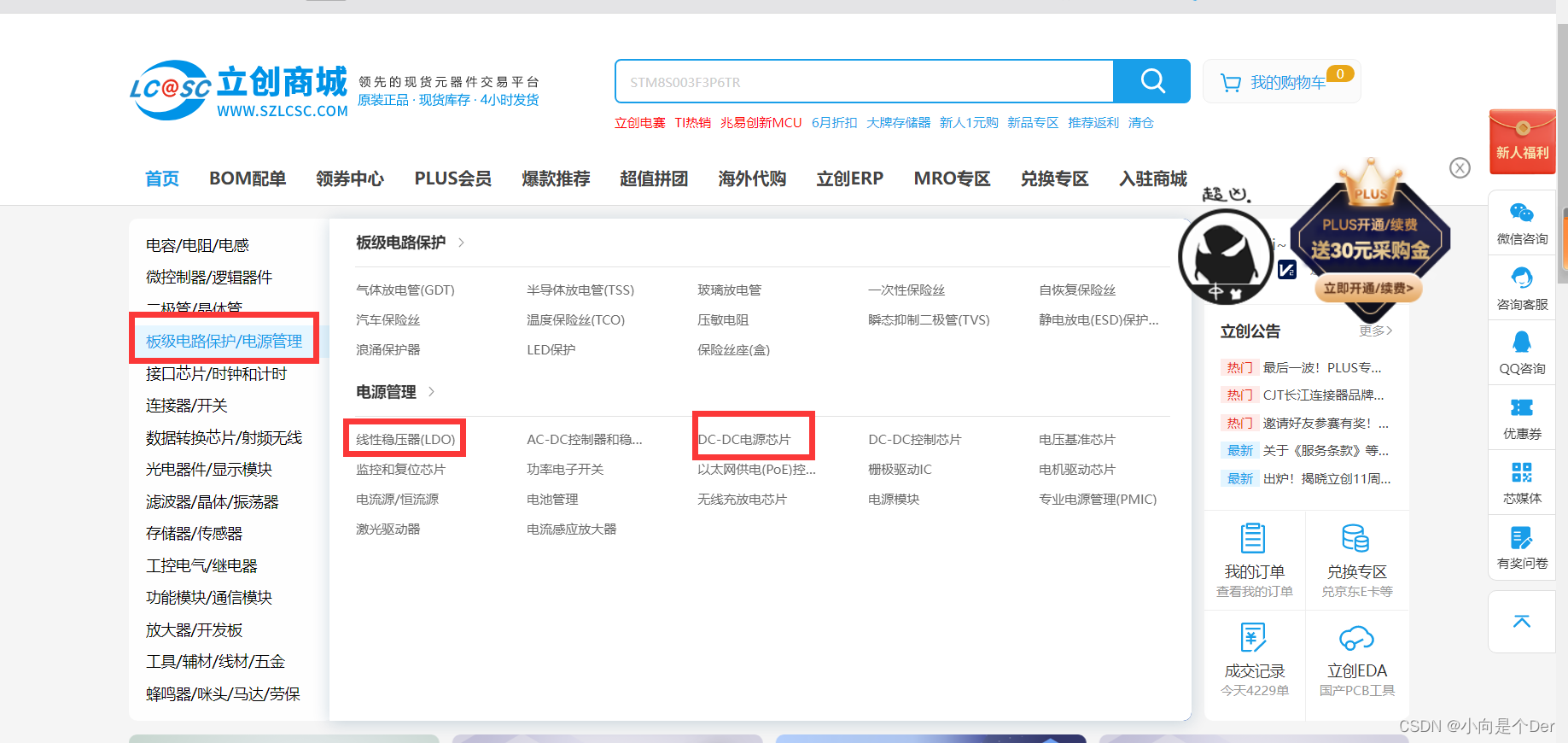
Then in the screening box, select the appropriate devices according to your own needs , Here is the fixed output selected by the author , Positive voltage , An output channel ,5V Voltage reference , Input 12V, Then click filter to find the recommended model .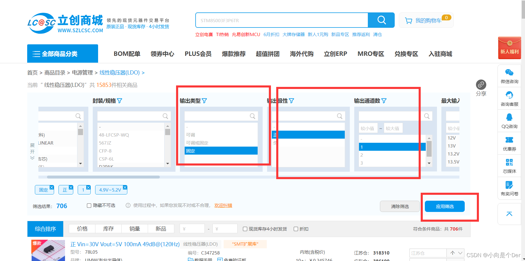
Here I choose L7805, When choosing, pay attention to the price and whether there is stock .
After selection , We also need to look at the reference circuit design of the data manual , similar DCDC There will also be layout suggestions , This must not be ignored .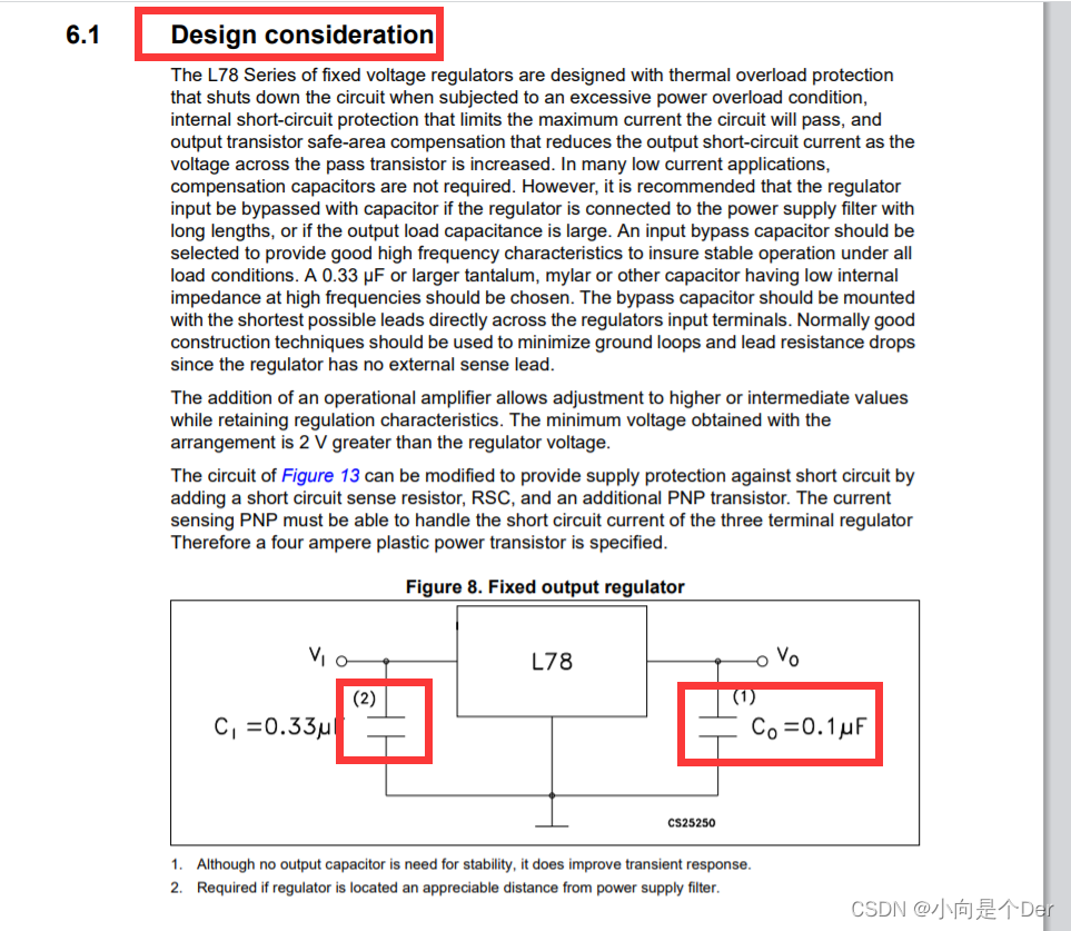
The reference circuit of this chip is shown in the figure above , Need to increase capacitance to achieve , In power supply design , Basically, a large capacitor will be added to all input and output power sources to filter out low-frequency noise , At the same time, it plays the role of energy storage , Prevent the voltage from being pulled down , There is also a small capacitor , It's usually 100nf Used to filter out high-frequency noise .
According to the above screening scheme , You need to choose one more 5V turn 3.3V Linear regulator , Here the author uses Youshun UZ1084G-3.3V. It is also a fixed voltage single channel output .
After determining these models , It also needs to be based on your own needs , Add input interface 、 switch 、 insurance 、 Anti reverse diode and other auxiliary devices .
Finally, the schematic diagram is drawn according to the chip manual and empirical values .
Current detection
In motor control , Current is a very important parameter , Excessive current will burn the drive circuit or even the motor .; So we need an electric detection circuit .
Obviously, the single-chip microcomputer cannot directly collect the current signal ; The most commonly used external semaphore is ADC To collect , Various semaphores are transformed by corresponding sensors , Convert into voltage signal , For SCM to collect , For current collection , It's the same thing , The most direct device that connects current and voltage is resistance , Just connect a small enough precision resistor into the circuit , The current can be converted into a voltage signal , This voltage signal is processed by the operational amplifier , Use ADC collection , Then the current value can be obtained according to the magnification and resistance value .
There are many schemes of current acquisition , Including high side current acquisition 、 Low side current acquisition , Two phase and three-phase diversion schemes .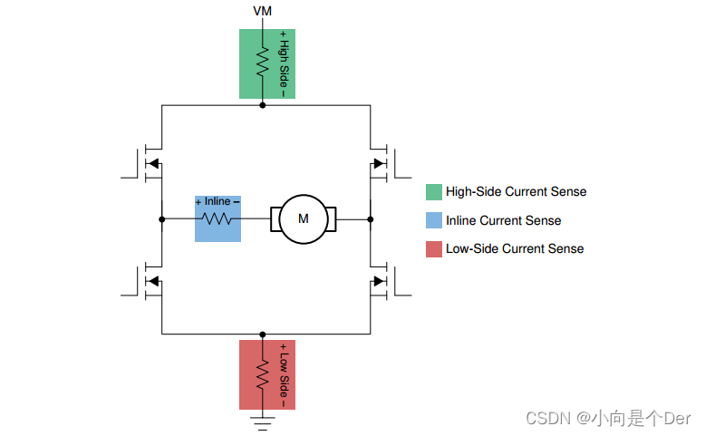
Here, the author chooses to collect the low side current of the two bridge arms and the total low side current .
After determining the collection method , It is necessary to start the model selection . About current detection , One scheme can be built directly with ordinary operational amplifiers , Another scheme is to use the special current amplifier . Both options are OK , The circuit of the former is a little complicated ., But it's cheap , The latter is slightly more expensive , But the circuit is simple .
Or in Lichuang mall , Select power management in the category , Then select the current sensing amplifier ,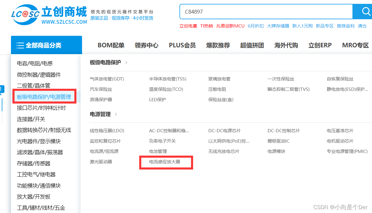
You can see a series of current detection chips , For the most part TI Of INA series , Here I choose INA199B1DCKR.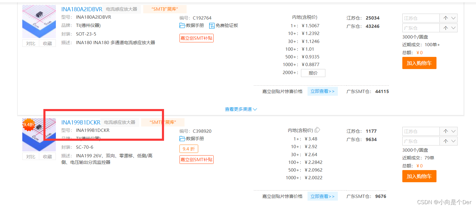
There are circuit design references in its chip manual , It is recommended to use this kind of input with Kelvin connection .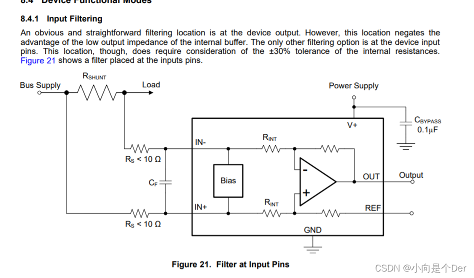
Another plan is the official reference plan of Xinyuan , Use LM358 To set up , This circuit is used in Brushless DC motor control —— be based on STM8S A series of single chip computers are introduced .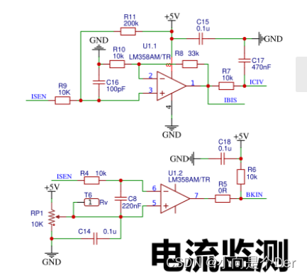
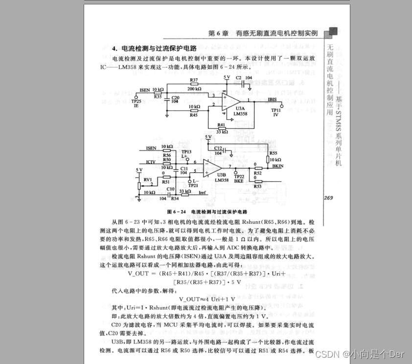
Grid drive and power circuit
Brushless DC motor needs to use three-phase bridge to drive , For specific driving principle, please refer to this article Understand the working principle and difference between brush motor and brushless motor The power circuit of the three-phase bridge is actually the same as that with only brush motor H The bridge is similar , Only a bridge arm is added on this basis . For the introduction and circuit design of this aspect, you can see Mr. Tang's explanation .
DC brushless motor BLDC,FOC,2022 The national college student intelligent car competition
Model selection , The author PMOS Selected KNY3404C, The grid drive is EG( Yijingwei ) Of 2133, The reference circuit of its chip manual is as follows :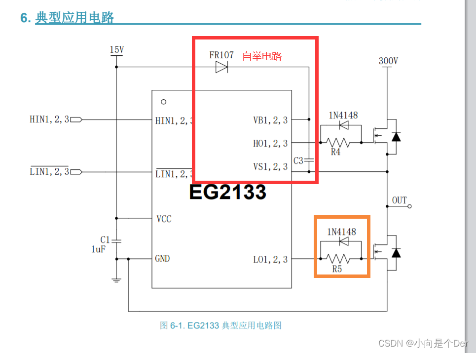
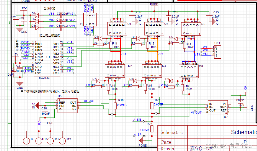
In the red box FR107 as well as C3 It forms a bootstrap circuit , For the introduction of bootstrap circuit, please refer to this article —— Principle analysis of bootstrap circuit . Then there are the resistors and diodes in the orange box , Their role is to eliminate MOS Ringing phenomenon when conducting , You can check this video about this phenomenon ——【 Give Way MOS It's worth burning Ring the bell , Explanation of stray inductance - Bili, Bili 】
About mos Study on the effect of the series connection resistance of the tube grid
On the basis of this reference circuit , The author also added a 10K One of the functions of this resistor is to give a certain level to the grid when the circuit is powered on , Prevent misleading communication when powered on , The second function is to Cgs Parasitic capacitance provides a discharge path , Consume the electric energy stored in the parasitic capacitor , For detailed introduction, please refer to this video ——【MOS The function of pull-down resistor on tube switch circuit - Bili, Bili 】.
The following is the circuit of the whole power part of the author's training camp :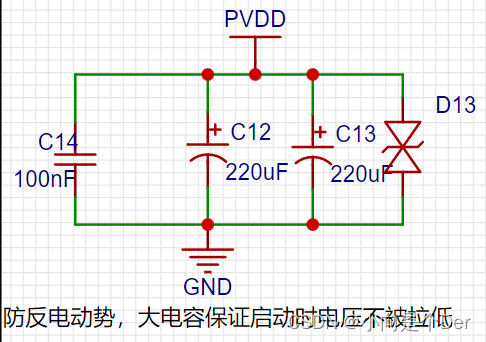
Isolate the circuit
Last , The author also adds an isolation circuit , Used to protect SCM IO mouth , There are many schemes for the isolation circuit here , Buffer chips can be used, such as 74HC245; You can also use an optocoupler , Here I use 74HC245 To achieve , The circuit diagram is as follows :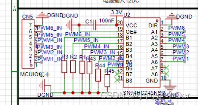
Examples of optocoupler isolation :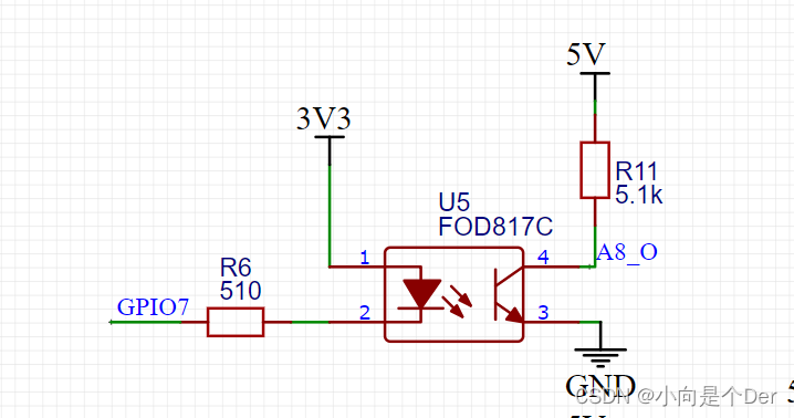
So far, the schematic part of the whole hardware circuit is roughly completed .
PCB Drawing considerations
There are many contents in this part , stay TI Special documents on the official website of , The link is left for you to learn by yourself :
1. Best practices for motor driver board layout ;
2. System design considerations for high-power motor driver applications ;
3. For the use of BLDC Precautions for hardware design of electric bicycle with electric motor .
In addition, you can also check the video of teacher Tang's video game above , Yes PCB The drawing of is also introduced .
Results the preview
Lichuang & Xinyuan brushless motor training camp
summary
Can successfully reproduce the function of the training camp , The author himself is still very happy , Also mastered a motor control mode , The author will update the relevant software from time to time , If there is any deficiency in the above content , Welcome criticism , Those who want to learn brushless motor can go B Stand and find Lichuang eda Playback with core source .
边栏推荐
- Summary of binary tree recursive routines
- Selenium+Pytest自动化测试框架实战
- Openresty ngx Lua regular expression
- PLC编程基础之数据类型、变量声明、全局变量和I/O映射(CODESYS篇 )
- ORB_ SLAM2/3
- LabVIEW打开PNG 图像正常而 Photoshop打开得到全黑的图像
- Multi camera stereo calibration
- Sum of two numbers, sum of three numbers (sort + double pointer)
- Registration of Electrical Engineering (elementary) examination in 2022 and the latest analysis of Electrical Engineering (elementary)
- 6-axis and 9-axis IMU attitude estimation
猜你喜欢
Practice of concurrent search

Douban scoring applet Part-2

查看网页最后修改时间方法以及原理简介
![[screen recording] how to record in the OBS area](/img/34/bd06bd74edcdabaf678c8d7385cae9.jpg)
[screen recording] how to record in the OBS area
Pyqt control part (I)

February 13, 2022-4-symmetric binary tree

Three.JS VR看房
Realize reverse proxy client IP transparent transmission
第十七周作业
One article deals with the microstructure and instructions of class
随机推荐
Development specification: interface unified return value format [resend]
poj 2762 Going from u to v or from v to u? (推断它是否是一个薄弱环节图)
Shell: operator
判斷二叉樹是否為完全二叉樹
Data type, variable declaration, global variable and i/o mapping of PLC programming basis (CoDeSys)
asp. Net pop-up layer instance
Idea rundashboard window configuration
leecode-学习笔记
Krypton Factor-紫书第七章暴力求解
Expectation, variance and covariance
【Note17】PECI(Platform Environment Control Interface)
Detailed explanation of pointer and array written test of C language
UVA – 11637 garbage remembering exam (combination + possibility)
Common JVM tools and optimization strategies
第十七周作业
yate.conf
秒杀系统的设计与实现思路
Déterminer si un arbre binaire est un arbre binaire complet
What is the process of building a website
CorelDRAW plug-in -- GMS plug-in development -- new project -- macro recording -- VBA editing -- debugging skills -- CDR plug-in (2)