当前位置:网站首页>The fledgling Xiao Li's 112th blog project notes: Wisdom cloud intelligent flower watering device actual combat (1) - basic Demo implementation
The fledgling Xiao Li's 112th blog project notes: Wisdom cloud intelligent flower watering device actual combat (1) - basic Demo implementation
2022-08-01 02:05:00 【fledgling li】
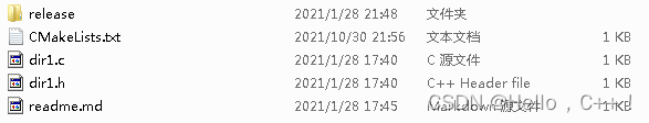
项目文件夹框架

- API文件夹---------------------------------------Place various sensor driver code folders
- CMSIS文件夹----------------------------------Place the kernel support files folder
- JIZHIYUN文件夹------------------------------Place the Gizwits platform docking file folder
- PROJECT文件夹------------------------------Put the project directory folder
- STARTUP文件夹------------------------------Put the startup code folder
- STM32F10x_StdPeriph_Driver文件夹—Place the standard library functions folder
- USER文件夹-----------------------------------A folder where some files necessary for the project are placed
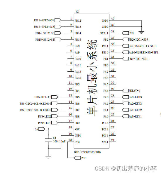
核心板原理图
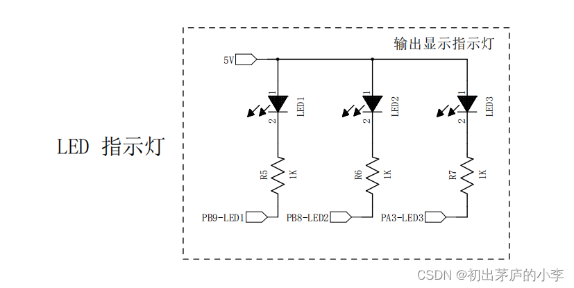
LED灯的驱动代码编写
原理图
代码实现
#include "led.h"
#include "systick.h"

void LED_Init(void)
{

	RCC_APB2PeriphClockCmd(LED1_CLK, ENABLE);
	RCC_APB2PeriphClockCmd(LED2_CLK, ENABLE);
	RCC_APB2PeriphClockCmd(LED3_CLK, ENABLE);

	GPIO_InitTypeDef            LED_InitStruct = {
    0};

	LED_InitStruct.GPIO_Pin   = LED1_PIN;
	LED_InitStruct.GPIO_Mode  = GPIO_Mode_Out_PP;
	LED_InitStruct.GPIO_Speed = GPIO_Speed_50MHz;

	GPIO_Init(LED1_PORT, &LED_InitStruct);

	LED_InitStruct.GPIO_Pin   = LED2_PIN;
	GPIO_Init(LED2_PORT, &LED_InitStruct);

	LED_InitStruct.GPIO_Pin   = LED3_PIN;
	GPIO_Init(LED3_PORT, &LED_InitStruct);

	LED1(0);
  LED2(0);
	LED3(0);
}

void LED_Task(void)
{

	static uint32_t Timer = 0;
	static uint8_t  Sta   = 0;
	if(SoftTimer(Timer,500))
	{

		Timer=GetSoftTimer();
		Sta?(Sta=0):(Sta=1);
		LED1(Sta);
		LED2(Sta);
		LED3(Sta);
	}
}

void GPIO_TogglePin(GPIO_TypeDef* GPIOx, uint16_t GPIO_Pin)
{

	uint32_t ODR;
	ODR = GPIOx->ODR;
	GPIOx->BSRR = ((ODR & GPIO_Pin) << 16U) | (~ODR & GPIO_Pin);
}
#ifndef __LED_H_
#define __LED_H_

#include "stm32f10x.h"


//PB9 --- LED1 --- 低有效
//PB8 --- LED2 --- 低有效
//PA3 --- LED3 --- 低有效

//基于STM32标准库 芯片是 STM32F103C8T6


#define LED1_CLK RCC_APB2Periph_GPIOB
#define LED1_PORT GPIOB
#define LED1_PIN GPIO_Pin_9

#define LED2_CLK RCC_APB2Periph_GPIOB
#define LED2_PORT GPIOB
#define LED2_PIN GPIO_Pin_8

#define LED3_CLK RCC_APB2Periph_GPIOA
#define LED3_PORT GPIOA
#define LED3_PIN GPIO_Pin_3


//宏定义的一个开关
#define LED1(X) X?(GPIO_ResetBits(LED1_PORT,LED1_PIN)):(GPIO_SetBits(LED1_PORT,LED1_PIN))
#define LED2(X) X?(GPIO_ResetBits(LED2_PORT,LED2_PIN)):(GPIO_SetBits(LED2_PORT,LED2_PIN))
#define LED3(X) X?(GPIO_ResetBits(LED3_PORT,LED3_PIN)):(GPIO_SetBits(LED3_PORT,LED3_PIN))

void LED_Init(void);
void GPIO_TogglePin(GPIO_TypeDef* GPIOx, uint16_t GPIO_Pin);
void LED_Task(void);

#endif
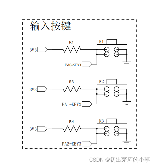
按键驱动的代码编写
原理图
代码实现
#include "key.h"
#include "systick.h"

void KEY_Init(void)
{

	RCC_APB2PeriphClockCmd(KEY0_CLK,ENABLE);
	RCC_APB2PeriphClockCmd(KEY1_CLK,ENABLE);
	RCC_APB2PeriphClockCmd(KEY2_CLK,ENABLE);

	GPIO_InitTypeDef            KEY_InitStruct;
	KEY_InitStruct.GPIO_Pin   = KEY0_PIN|KEY1_PIN|KEY2_PIN;
	KEY_InitStruct.GPIO_Mode  = GPIO_Mode_IPU;
	KEY_InitStruct.GPIO_Speed = GPIO_Speed_50MHz;

	GPIO_Init(KEY0_PORT ,&KEY_InitStruct);
	GPIO_Init(KEY1_PORT ,&KEY_InitStruct);
	GPIO_Init(KEY2_PORT ,&KEY_InitStruct);

}


static uint8_t Key0Value=0;
static uint8_t Key1Value=0;
static uint8_t Key2Value=0;

void KeyScan(void)
{

	static uint16_t Key0Timer=0;
	static uint16_t Key1Timer=0;
	static uint16_t Key2Timer=0;
	if(KEY0==0)
	{

		if(Key0Timer<10)
		{

			Key0Timer++;
			if(Key0Timer>=10)
				Key0Value=1;
		}
	}
	else
	{

		Key0Timer = 0;
	}
	if(KEY1==0)
	{

		if(Key1Timer<10)
		{

			Key1Timer++;
			if(Key1Timer>=10)
				Key1Value=1;
		}
	}
	else
	{

		Key1Timer = 0;
	}
	if(KEY2==0)
	{

		if(Key2Timer<10)
		{

			Key2Timer++;
			if(Key2Timer>=10)
				Key2Value=1;
		}
	}
	else
	{

		Key2Timer = 0;
	}
}


uint8_t GetKey0(void)
{

	uint8_t Key=Key0Value;
	Key0Value=0;
	return Key;
}

uint8_t GetKey1(void)
{

	uint8_t Key=Key1Value;
	Key1Value=0;
	return Key;
}

uint8_t GetKey2(void)
{

	uint8_t Key=Key2Value;
	Key2Value=0;
	return Key;
}
#ifndef __KEY_H_
#define __KEY_H_

#include "stm32f10x.h"

#define KEY0_CLK RCC_APB2Periph_GPIOA
#define KEY0_PORT GPIOA
#define KEY0_PIN GPIO_Pin_0

#define KEY1_CLK RCC_APB2Periph_GPIOA
#define KEY1_PORT GPIOA
#define KEY1_PIN GPIO_Pin_1

#define KEY2_CLK RCC_APB2Periph_GPIOA
#define KEY2_PORT GPIOA
#define KEY2_PIN GPIO_Pin_2

#define KEY0 GPIO_ReadInputDataBit(KEY0_PORT,KEY0_PIN)
#define KEY1 GPIO_ReadInputDataBit(KEY1_PORT,KEY1_PIN)
#define KEY2 GPIO_ReadInputDataBit(KEY2_PORT,KEY2_PIN)

void KEY_Init(void);
void KeyScan(void);
uint8_t GetKey0(void);
uint8_t GetKey1(void);
uint8_t GetKey2(void);
#endif
测试驱动程序的正确性
#include "main.h"
int main(void)
{

	NVIC_PriorityGroupConfig(NVIC_PriorityGroup_2);
	USART1_Init(9600);
	//printf("打印串口初始化 OK !\r\n");
  SysTick_Init();
  //printf("系统嘀嗒初始化 OK !\r\n");
	LED_Init();
  //printf("状态指示初始化 OK !\r\n");
  KEY_Init();
  //printf("按键配置初始化 OK !\r\n");
	while(1)
	{

		LED_Task();
		if(GetKey0())
		{

			GPIO_TogglePin(LED1_PORT,LED1_PIN);
			//JiaoHua(1-currentDataPoint.valueRelay_1);
		}
		if(GetKey1())
		{

			GPIO_TogglePin(LED2_PORT,LED2_PIN);
			//gizwitsSetMode(WIFI_AIRLINK_MODE);
			//按键进入配网模式
		}
		if(GetKey2())
		{

			GPIO_TogglePin(LED3_PORT,LED3_PIN);
		}
	}
}
其他辅助代码
串口打印实现
在开发板上用的是USB TO TTL 工具 串口1 打印 实际的项目板上没有设计该电路(失误1)
串口1 驱动代码
#include "usart1.h"
#include <stdio.h>

void USART1_NVIC_Config(void)
{

  //接收中断使能
	NVIC_InitTypeDef  NVIC_InitStruct;
	/*NVIC控制器配置*/
	NVIC_InitStruct.NVIC_IRQChannel    = USART1_IRQn;//具体中断源名字
	NVIC_InitStruct.NVIC_IRQChannelCmd = ENABLE;//NVIC响应通道使能
	NVIC_InitStruct.NVIC_IRQChannelPreemptionPriority = 0;//抢占优先级值
	NVIC_InitStruct.NVIC_IRQChannelSubPriority        = 1;//响应优先级别值
  NVIC_Init(&NVIC_InitStruct);

}

/*打印调试串口*/
void USART1_Init(uint32_t BaudRate)
{

	USART_DeInit(USART1);
	//1.打开GPIO的时钟
	RCC_APB2PeriphClockCmd(RCC_APB2Periph_GPIOA,ENABLE);

	//2.配置相关结构体
	GPIO_InitTypeDef           GPIO_InitStruct;

	//串口发送引脚的配置 PA9->复用推挽输出
	GPIO_InitStruct.GPIO_Pin   = GPIO_Pin_9;
	GPIO_InitStruct.GPIO_Mode  = GPIO_Mode_AF_PP;
	GPIO_InitStruct.GPIO_Speed = GPIO_Speed_50MHz;
	GPIO_Init(GPIOA,&GPIO_InitStruct);

	//串口接收引脚的配置 PA10->浮空输入模式
	GPIO_InitStruct.GPIO_Pin   = GPIO_Pin_10;
	GPIO_InitStruct.GPIO_Mode  = GPIO_Mode_IN_FLOATING;//浮空输入模式
	GPIO_InitStruct.GPIO_Speed = GPIO_Speed_50MHz;
	GPIO_Init(GPIOA,&GPIO_InitStruct);

	//1.打开串口的时钟
	RCC_APB2PeriphClockCmd(RCC_APB2Periph_USART1,ENABLE);//注意APB2

	USART_InitTypeDef USART1_InitStruct;
	//串口的参数配置 波特率可以更改
	//无硬件流控制 收发模式
	//1起始位 8数据位 无奇偶校验 1位停止位
	USART1_InitStruct.USART_BaudRate            = BaudRate;
	USART1_InitStruct.USART_HardwareFlowControl = USART_HardwareFlowControl_None;
	USART1_InitStruct.USART_Mode                = USART_Mode_Rx|USART_Mode_Tx;
	USART1_InitStruct.USART_Parity              = USART_Parity_No;
	USART1_InitStruct.USART_StopBits            = USART_StopBits_1;
	USART1_InitStruct.USART_WordLength          = USART_WordLength_8b;
	//串口1初始化
	USART_Init(USART1,&USART1_InitStruct);

	/**************************************************************/
	//开串口中断
	USART_ITConfig(USART1, USART_IT_RXNE, ENABLE);//接收中断
	//USART_ITConfig(USART1, USART_IT_IDLE, ENABLE);//空闲中断
	//中断优先级配置
	USART1_NVIC_Config();
	USART_Cmd(USART1,ENABLE);
}


/*串口重定向函数 目的是让STM32支持printf("%d %x %c ")*/
int fputc(int ch , FILE *stream)
{

	while(USART_GetFlagStatus(USART1,USART_FLAG_TXE)==RESET);
	USART_SendData(USART1,(uint16_t) ch); //数据通过串口发送
	while(USART_GetFlagStatus(USART1,USART_FLAG_TC)==RESET);
	return ch;
}
#ifndef __USART1_H_
#define __USART1_H_

#include "stm32f10x.h"

void USART1_Init(uint32_t BaudRate);

#endif
系统嘀嗒定时器代码
#include "systick.h"
#include "key.h"


uint32_t mySysTick_Config(uint32_t ticks)
{

  if (ticks > SysTick_LOAD_RELOAD_Msk)  return (1);            /* Reload value impossible */

  SysTick->LOAD  = (ticks & SysTick_LOAD_RELOAD_Msk) - 1;      /* set reload register */
  NVIC_SetPriority (SysTick_IRQn, (1<<__NVIC_PRIO_BITS) - 1);  /* set Priority for Cortex-M0 System Interrupts */
  SysTick->VAL   = 0;                                          /* Load the SysTick Counter Value */
  SysTick->CTRL  = SysTick_CTRL_CLKSOURCE_Msk |
                   SysTick_CTRL_TICKINT_Msk   |
                   SysTick_CTRL_ENABLE_Msk;                    /* Enable SysTick IRQ and SysTick Timer */
  return (0);                                                  /* Function successful */
}

void SysTick_Init(void)
{

	//SystemInit();
	SysTick_CLKSourceConfig(SysTick_CLKSource_HCLK);
	mySysTick_Config(SystemCoreClock/1000);
}
void SysTick_Handler(void)
{

	SystemTick();
	KeyScan();
}
static uint32_t Ticks=0;
void SystemTick(void)
{

	Ticks++;
}
uint32_t GetSoftTimer(void)
{

	return Ticks;
}
uint8_t SoftTimer(uint32_t BaseTimer,uint32_t Timeout)
{

	if(Ticks>=BaseTimer)
	return (Ticks)>=Timeout+BaseTimer;
	return (Ticks+0xFFFFFF)>=Timeout+BaseTimer;
}
边栏推荐
- RTL8762DK 点灯/LED(三)
- MYSQL two-phase commit
- 纽约大学等 | TM-Vec:用于快速同源检测和比对的模版建模向量
- Simple vim configuration
- Compiled on unbutu with wiringPi library and run on Raspberry Pi
- Item 36: Specify std::launch::async if asynchronicity is essential.
- 普通用户无法访问hgfs目录
- Daily practice of LeetCode - Circular linked list question (interview four consecutive questions)
- ARM 交叉编译
- 【密码学/密码分析】基于TMTO的密码分析方法
猜你喜欢
Cmake introductory study notes

Replacing the Raspberry Pi Kernel
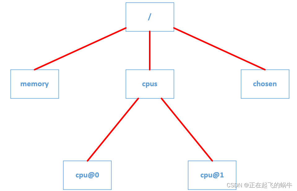
设备树的树形结构到底是怎样体现的?

Four ways the Metaverse is changing the way humans work

RTL8762DK UART (two)
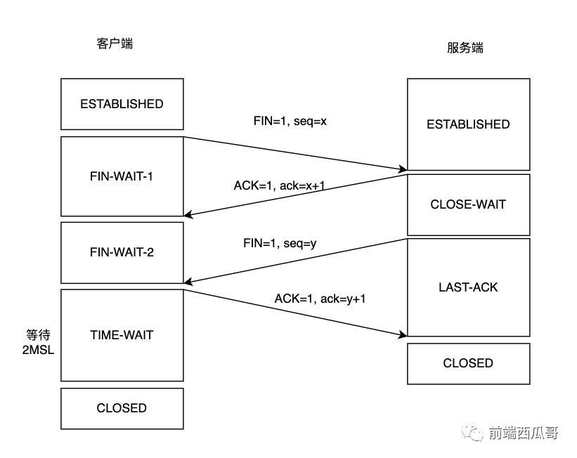
You need to know the TCP wave four times

ECCV2022 Workshop | Multi-Object Tracking and Segmentation in Complex Environments

【分层强化学习】HIRO:Data-Efficient Hierarchical Reinforcement Learning

【密码学/密码分析】基于TMTO的密码分析方法
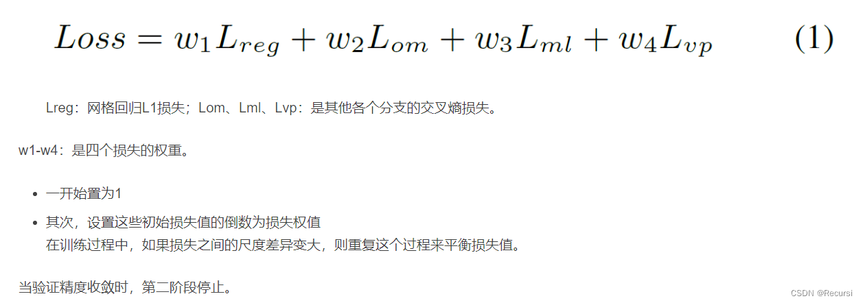
VPGNet
随机推荐
Js replication
By Value or By Reference
VPGNet
从零造键盘的键盘超级喜欢,IT人最爱
RTL8762DK RTC (5)
Unity3D study notes 10 - texture array
July Bootcamp (Day 31) - Status Compression
Nmap 操作手册 - 完整版
手写二叉查找树及测试
如何编辑epub电子书的目录
date command
MYSQL master-slave replication
Flink 部署和提交job
链式编程、包、访问权限
What practical projects can machine learning beginners learn?
IDEA modifies the annotation font
【历史上的今天】7 月 31 日:“缸中之脑”的提出者诞生;Wi-Fi 之父出生;USB 3.1 标准发布
高维高斯分布基础
SC7A20 (Silan Micro-Accelerometer) Example
解决安装MySQL后,Excel打开很慢的问题