当前位置:网站首页>MATLAB realizes mean filtering and FPGA for comparison, and uses Modelsim waveform simulation
MATLAB realizes mean filtering and FPGA for comparison, and uses Modelsim waveform simulation
2022-06-11 06:06:00 【Fighting_ XH】
List of articles
The method and Joint simulation implementation Ycbcr The same way . Don't repeat .
One 、 The goal of the experiment
stay Ycbcr Average filtering based on grayscale .
Two 、 Problems encountered in the experiment
1、 How to realize mean filtering
2、modelsim Simulation involves IP What if the nuclear does not exist ?
Here's the picture , We call shift_ram ip nucleus , Without adding a library file , Error occurs in independent simulation

resolvent :
Add the device library .
choice simulation —— start simulation——Libraries——Add, Add library file 
Location of library file :modelsim Installation position ,modelsim-ase——aletra——Verilog——altera_mf || cyclonev( Select according to the model of the development board used )

3、 ... and 、 Concrete realization
3.1 The realization of mean filtering
1、 This section contains two modules :3*3 Window generation module as well as Mean filter algorithm modular .( Refer to other blog posts , The theory part is not explained )
2、33 Window generation module :filter_33;—— Called shift_ram ip nucleus .
3、 Mean filter module :mean_filter;—— use Three stage assembly line The way to deal with . Pipeline technology is FPGA Common ideas .
3.1.1 call shift_ram ip nucleus :

3.1.2 Pipelining parallel processing of mean filter
As follows, we can get the formula of mean filtering :mean_data = P11 + P12 + P13 + P21 + P23 + P31 +P32 + P33 / 8; Disassemble it into Three stage pipeline parallel processing In the form of :
First stage pipeline parallel processing :
P1 = P11 + P12 + P13 ;P2 = P21 + P23 ;P3 = P31 +P32 + P33;
.
The second stage pipeline processing :
P = P1 + P2 + P3;
.
The third stage pipeline processing :
P >> 3 Or take the high position

3.2 Overall module design
Image generation module (VGA modular + Data acquisition );
Ycbcr Grayscale module ;
3*3 Window generation module ;
Mean filter module :
3.2.1 Image generation module
module img_gen (
// System global signal
input	wire			       	clk			,
input	wire				     rst_n		,
// Original image output  ----------------------------------------
output	wire				   img_hsync	,	// Original line synchronization signal
output	wire				   img_vsync	,	// Field synchronization signal
output	reg  	[23:0]		   img_data		,	// Original image data signal
output	reg					   img_de			// Data valid indication signal
);
endmodule
The module data is obtained as follows :
When quartus see RTL In the picture , Because it cannot be integrated , Just lead it away .
initial begin
	$readmemh("pre_img.txt", ram);
end
3.2.2 Ycbcr Graying
module RGB_Gray
//========================<  port  >==========================================
(
input   wire				clk		,	// The clock
input   wire				rst_n	,	// Reset
// Original picture  ----------------------------------------------
input   wire				RGB_hsync,
input   wire				RGB_vsync,
input   wire    [23:0]      RGB_data,
input   wire				RGB_de ,
// Gray scale conversion diagram  ----------------------------------------------
// The line field effective signal and data signal here beat three times according to the consumption clock , As the next module input
output  wire			gray_hsync,
output  wire			gray_vsync,
output  wire			gray_de,
output  wire	[7:0]	gray_data

);
3.2.3 3*3 Window generation
module filter_3x3(
    input clk,
    input rst_n,
// After grayscale shooting, the line field is effective and the data is effective
    input  gray_hsync,
    input  gray_vsync,
    input  gray_de   ,

    input [7:0] iData,
// according to 3*3 The window generation module actually consumes the clock to delay
    output  filter_hsync,
    output  filter_vsync				,
    output  filter_de,
// Generated 3*3 Window data
    output reg [7:0] oData_11, oData_12, oData_13,
    output reg [7:0] oData_21, oData_22, oData_23,
    output reg [7:0] oData_31, oData_32, oData_33
);
3.2.4 Mean filter module
module mean_filter(
    input clk,
    input rst_n,

// come from 3*3 Window generation module
	input   wire				filter_hsync				,
    input   wire				filter_vsync				,
    input   wire				filter_de					,
// Generated 3*3 Window data
    input   [7:0]     filter_11,filter_12,filter_13,
    input   [7:0]     filter_21,filter_22,filter_23,
    input   [7:0]     filter_31,filter_32,filter_33,
// Field after mean processing 、 The data valid signal beats according to the consumption clock
	output  			  mean_hsync			  	,
    output  			  mean_vsync				,
    output  			  mean_de    ,
    output   [7:0]     mean_data  //  Final mean ,3x3 Template sum /8

);
3.3 Waveform simulation verification
1、tb The test file remains unchanged .
Still processed 640*480 Data written to txt In the document .
// open post_img.txt file
//---------------------------------------------------
integer post_img_txt;

initial begin
    post_img_txt = $fopen("post_img.txt");
end

// Pixels are written to txt in
//---------------------------------------------------
reg [20:0] pixel_cnt; //640*480 = 307200 , Write these pixels one by one

always @(posedge clk) begin
    if(!rst_n) begin
        pixel_cnt <= 0;
    end
    else if(VGA_de) begin
        pixel_cnt = pixel_cnt + 1;
        $fdisplay(post_img_txt,"%h",VGA_data);

        if(pixel_cnt == IMG_H*IMG_W)
            $stop;
    end
end
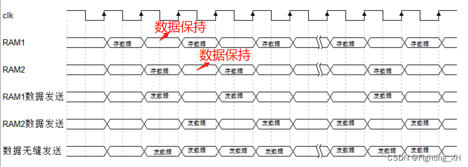
2、 Waveform analysis
Take the first row of data as an example
img_de : Original data valid signal
img_data: Original data
gray_de: Grayscale data effective signal
gray_data: Grayscale image data = iData
filter_de : 33 The window generates a data valid signal
oData11 - 33 :33 Window data
mean_de : Mean filter data effective signal
mean_data : 3*3 The mean value of the window data
VGA_de : VGA Valid data signal = mean_de
The first mean :164 / 8 = 20
The second mean :(164 + 1580) / 8 = 40
The third mean :(164 + 158 + 153 ) / 8= 59 ……
matlab Realize mean filtering
matlab Mean filtering :
x=imread('pre_img.jpg');% Images to be filtered
n=3;    % Template size
[height, width]=size(x);   % Get the size of the image (n Less than the width and height of the picture )
gdata = rgb2gray(x);
imshow(gdata),title(' The original image is grayed ');
for i=1:height-n+1
    for j=1:width-n+1
        c=x(i:i+(n-1),j:j+(n-1)); % stay x1 A block of template size from scratch is assigned to c
        e=c(1,:);      %e Stored in is c The first line of the matrix
        for u=2:n  % take c Take out the other line elements in and connect them to e Post emissary e For a row matrix
            e=[e,c(u,:)];
        end
        s=sum(e);      % Take the sum of a line
        x2(i+(n-1)/2,j+(n-1)/2)=s/(n*n);   % Assign the average value of each element of the template to the element at the center of the template
    end
end
d=uint8(x);  % The unassigned element takes the original value
C=rgb2gray(x);  % Grayscale processing , The gray processed image is a two-dimensional matrix
A=fspecial('average',[n,n]);  %matlab Filter function with value in
b=imfilter(C,A);
figure;
imshow(b),title(' Mean filtering '); % Display the filtered grayscale image
imwrite(b,'matlab Mean filtering .jpg');
result :
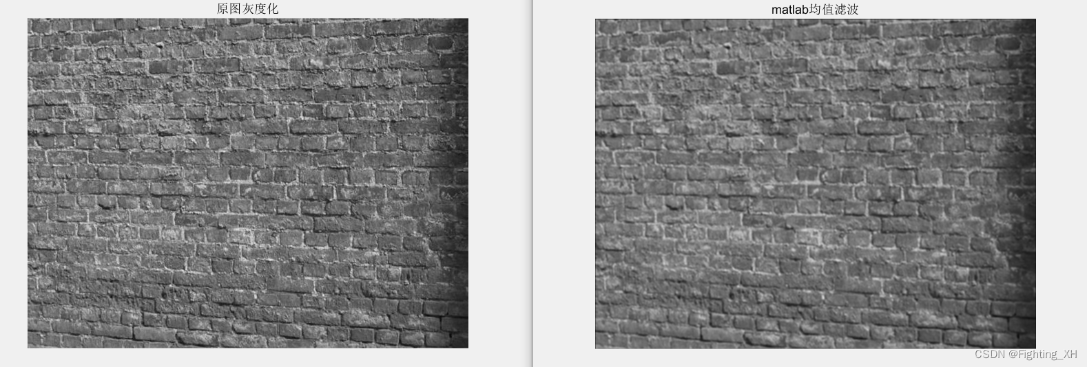

Because there are precision problems in gray processing and mean filtering , May cause and matllab There is a slight difference in the processed pixel values . Is not the point , Observe the effect of mean filtering , It can be seen that the images after the average filtering of both become blurred .
边栏推荐
- Basic usage of MySQL
- JIRA software annual summary: release of 12 important functions
- Sword finger offer 04: find in 2D array
- All the benefits of ci/cd, but greener
- Installing MySQL for Linux
- 我们真的需要会议耳机吗?
- Servlet
- 数组部分方法
- Reading the registry using batch
- FPGA面试题目笔记(四)—— 序列检测器、跨时钟域中的格雷码、乒乓操作、降低静动态损耗、定点化无损误差、恢复时间和移除时间
猜你喜欢

Cenos7 builds redis-3.2.9 and integrates jedis
![[元数据]LinkedIn-DataHub](/img/6a/247ee77dfc219d26651e5d93b04c98.png)
[元数据]LinkedIn-DataHub

Do you know the functions of getbit and setbit in redis?
FPGA设计——乒乓操作实现与modelsim仿真

How to use perforce helix core with CI build server

Yonghong Bi product experience (I) data source module

Super details to teach you how to use Jenkins to realize automatic jar package deployment

Thymeleafengine template engine
![Chapter 1 of machine learning [series] linear regression model](/img/e2/1f092d409cb57130125b0d59c8fd27.jpg)
Chapter 1 of machine learning [series] linear regression model
数据接入平台方案实现(游族网络)
随机推荐
亚马逊、速卖通、Lazada、虾皮平台在用911+VM的环境可以进行产号、养号、补单等操作吗?
Squid agent
11. Gesture recognition
Free get | full function version of version control software
The meaning in the status column displayed by PS aux command
Write a list with kotlin
"All in one" is a platform to solve all needs, and the era of operation and maintenance monitoring 3.0 has come
Sign for this "plug-in" before returning home for the new year
Installing and using sublist3r in Kali
Chapter 6 of machine learning [series] random forest model
Chapter 4 of machine learning [series] naive Bayesian model
Servlet
Pycharm usage experience
修复Yum依赖冲突
Sword finger offer 32: print binary tree from top to bottom
[IOS development interview] operating system learning notes
Which company is better in JIRA organizational structure management?
NFC Development -- the method of using NFC mobile phones as access control cards (II)
Global case | how Capgemini connects global product teams through JIRA software and confluence
What do you need to know about Amazon evaluation?