当前位置:网站首页>Solve the problem that stc8g1k08 program cannot run and port configuration
Solve the problem that stc8g1k08 program cannot run and port configuration
2022-06-27 00:53:00 【arenascat】
Some time ago I got some samples , Then go to the board test

Automatic operation after power on IO Alternate output program , That is, the factory procedure . This proves that there is no problem with playing the board , It can be used normally. .

But here's the problem , I find my own program doesn't work . For example, such a simple lighting program .
#include "reg51.h"
#include "intrins.h"
sbit led1 = P1^1;
sbit led2 = P1^2;
sbit led3 = P1^3;
sbit led4 = P1^4;


void delay(int tim)		//@11.0592MHz
{
	unsigned char i, j;

	i = 20;
	j = 109;
	for(i=0;i<tim;i++)
	{
		do
	{
		while (--j);
	} while (--i);
	}

}


void main()
{
	while(1)
	{
		led2 = 1;
		delay(200);
		led2 = 0;
		delay(200);
	}
}
Then find out why , First, let's look and say 3.0 3.1 3.2 At least one pin must be pulled up , Then I will pull up , I got one 10k Resistance in VCC and P3.0 Between .
The result is , Not yet. , What kind of situation is this ?
I read the manual later , Find such a passage ,IO In this generation (STC-Y6) Must be manually configured in , Can not continue to use the previous C51 SCM development thinking , Direct assignment .

So how to configure input and output , This is in STC-ISP The example program on the software is in the window , Just copy it

So the code is modified as follows , The port mode setting has been added
#include "reg51.h"
#include "intrins.h"
sbit led1 = P1^1;
sbit led2 = P1^2;
sbit led3 = P1^3;
sbit led4 = P1^4;

sfr     P0M0        =   0x94;
sfr     P0M1        =   0x93;
sfr     P1M0        =   0x92;
sfr     P1M1        =   0x91;
sfr     P2M0        =   0x96;
sfr     P2M1        =   0x95;
sfr     P3M0        =   0xb2;
sfr     P3M1        =   0xb1;
sfr     P4M0        =   0xb4;
sfr     P4M1        =   0xb3;
sfr     P5M0        =   0xca;
sfr     P5M1        =   0xc9;
sfr     P6M0        =   0xcc;
sfr     P6M1        =   0xcb;
sfr     P7M0        =   0xe2;
sfr     P7M1        =   0xe1;

void delay(int tim)		//@11.0592MHz
{
	unsigned char i, j;

	i = 20;
	j = 109;
	for(i=0;i<tim;i++)
	{
		do
	{
		while (--j);
	} while (--i);
	}

}


void main()
{
	P1M0 = 0x00;                                //Set P1 OUTPUT
  P1M1 = 0x00;
	while(1)
	{
		led1 = 1;
		delay(200);
		led1 = 0;
		delay(200);
	}
}
The official tutorial also has a similar , For example, configure the two-way port read / write operation .
#include "reg51.h"
#include "intrins.h"

sfr     P0M0        =   0x94;
sfr     P0M1        =   0x93;
sbit    P00         =   P0^0;

void main()
{
    P0M0 = 0x00;                                // Set up P0.0~P0.7 It is a two-way port mode
    P0M1 = 0x00;

    P00 = 1;                                    //P0.0 Port output high level
    P00 = 0;                                    //P0.0 Port output low level

    P00 = 1;                                    // Enable the internal weak pull-up resistor before reading the port
    _nop_();                                    // Wait two clocks
    _nop_();                                    //
    CY = P00;                                   // Read port status

    while (1);
}
But still not , At this time, I went to look for someone else's code , Like this one https://oshwhub.com/Fangbrbr/lu-you-zhuai-jie
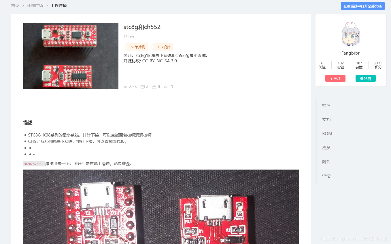
I read it for a while before I knew , indicating surprise or wonder , The original header file has now become a new one , It was time to develop , Is to use #include "reg51.h" Now this sentence has become #include "STC8.h" , And I didn't use it, so I couldn't let LED Light up .
#include "intrins.h"
#include "STC8.h"


void Delay300ms()		//@24.000MHz
{
	unsigned char i, j, k;

	_nop_();
	_nop_();
	i = 37;
	j = 135;
	k = 138;
	do
	{
		do
		{
			while (--k);
		} while (--j);
	} while (--i);
}

void main()
{
	P1M0=0x00;
	P1M1=0x00;
  while(1)
	{
		P11=0;
		Delay300ms();
		P11=1;
		Delay300ms();
   }
}
Modify your own code , The main thing is to change the header file , Because the new header file has basically defined some definitions , So many do not need to be in main Then write in the document
#include "STC8.h"
#include "intrins.h"
sbit led1 = P1^1;
sbit led2 = P1^2;
sbit led3 = P1^3;
sbit led4 = P1^4;


void delay(int tim)		//@11.0592MHz
{
	unsigned char i, j;
  int k;
	i = 15;
	j = 90;
	for(k=0;k<tim;k++)
	{
			do
		{
			while (--j);
		} while (--i);
	}

}


void main()
{
	P1M0 = 0x00;                                //Set P1 OUTPUT
  P1M1 = 0x00;
	P1 = 0x00;
	while(1)
	{
    delay(10);
		P1 = P1<<1;
		delay(10);
		if(P1==0)
		{
		P1 = 0x01;
		}
		if(P1>0x0F)
		{
			P1 = 0x00;
		}
	}
}
OK, Now the test is successful

Port configuration
be-all I/O Every mouth has 4 Working mode : Quasi two-way port / Weak pull-up ( standard 8051 Output port mode )、 Push pull output / Strong pull up 、 high Resistive input ( Current can neither flow in nor out )、 Open drain output . Software can be used to I/O The working mode of the port is easy to configure
except P3.0 and P3.1 Outside , All the rest I/O After the port is powered on, the state is high resistance input state , The user is making use I/O The port must be set first I/O Mouth mode
   P0M0 = 0x00;                                // Set up P0.0~P0.7 It is a two-way port mode
    P0M1 = 0x00;
    P1M0 = 0xff;                                // Set up P1.0~P1.7 For push-pull output mode
    P1M1 = 0x00;
    P2M0 = 0x00;                                // Set up P2.0~P2.7 High impedance input mode
    P2M1 = 0xff;
    P3M0 = 0xff;                                // Set up P3.0~P3.7 Open drain mode
    P3M1 = 0xff;
How to set up , For example, all the P1 and P3 The interface is set to bidirectional mode , The current is weak at this time
P1M0 = 0x00;                                //Set P1 OUTPUT
P1M1 = 0x00;
P3M0 = 0x00;                                //Set P3 OUTPUT
P3M1 = 0x00;
Then I need to use P37 As push-pull output , At this time, you can use this sentence ( The header file is required to contain STC8.h)
P3PU = 0x40;Besides the first time, there is Schmidt trigger control register PxNCS, Level rate conversion PxSR, Current control register PxDR, Input enable register PxIE
(x=0,1,2,3,4,5....)
STC8GK01 Electrical characteristics of

边栏推荐
- 深度学习方法求解平均场博弈论问题
- Encapsulation of unified result set
- 3-wire SPI screen driving mode
- 2022年地理信息系统与遥感专业就业前景与升学高校排名选择
- 温故知新--常温常新
- Technical dry goods | what is a big model? Oversized model? Foundation Model?
- 如何通俗易懂的描述机器学习的流程?
- 气液滑环与其他滑环的工作原理有什么区别
- [UVM actual battle== > episode_3] ~ assertion, sequence, property
- ESP32-添加多目录的自定义组件
猜你喜欢

Technical dry goods | what is a big model? Oversized model? Foundation Model?

【Vscode】预览md文件

Amway! How to provide high-quality issue? That's what Xueba wrote!
![寻找旋转排序数组中的最小值 II[经典抽象二分 + 如何破局左中右三者相等]](/img/75/05d5765588dfde971167fbc72e2aa8.png)
寻找旋转排序数组中的最小值 II[经典抽象二分 + 如何破局左中右三者相等]

Lwip之ARP模块实现

Flink 实战问题(七):No Watermark(Watermarks are only available EventTime is used)

2022年地理信息系统与遥感专业就业前景与升学高校排名选择

Batch generate folders based on file names

其他服务注册与发现

这3个并发编程的核心,竟然还有人不知道?
随机推荐
Gaussian and Summary Stats
Encapsulate servlet unified processing request
Kubernetes visual interface dashboard
com.fasterxml.jackson.databind.exc.MismatchedInputException: Expected array or string. at [Source:x
滑环选型选购时需要注意的技巧
No clue about complex data?
墨者学院-X-Forwarded-For注入漏洞实战
2022年地理信息系统与遥感专业就业前景与升学高校排名选择
BootstrapBlazor + FreeSql实战 Chart 图表使用(2)
Xiaobai looks at MySQL -- installing MySQL in Windows Environment
气液滑环与其他滑环的工作原理有什么区别
光谱共焦如何测量玻璃基板厚度
Review the old and know the new -- constant renewal at normal temperature
2022年地理信息系统与遥感专业就业前景与升学高校排名选择
com. fasterxml. jackson. databind. exc.MismatchedInputException: Expected array or string. at [Source:x
Com. Faster XML. Jackson. DataBind. Exc.mismatchedinputexception: tableau ou chaîne attendu. At [Source: X
Oracle database basics concepts
“message“:“Bad capabilities. Specify either app or appTopLevelWindow to create a session“
com.fasterxml.jackson.databind.exc.MismatchedInputException: Expected array or string. at [Source:x
Lorsque le transformateur rencontre l'équation différentielle partielle