当前位置:网站首页>Experiment collection of University "Fundamentals of circuit analysis". Experiment 7 - Research on sinusoidal steady-state circuit
Experiment collection of University "Fundamentals of circuit analysis". Experiment 7 - Research on sinusoidal steady-state circuit
2022-07-02 15:45:00 【Computer programmer ape】
experiment 7、 ... and Research on sinusoidal steady state circuit
Catalog
2 Experimental instruments and equipment
4 Experimental requirements and precautions
6 Experiment content and steps
7 Experimental report and thinking questions
1 The experiment purpose
1. understand R、L、C The relationship between the voltage and current at the component end .
2. Study the phasor relationship between voltage and current in sinusoidal steady-state circuit .
3. Learn how to use a dual trace oscilloscope to measure the phase difference of the same frequency signal .
2 Experimental instruments and equipment
A multimeter a
Integrated circuit test box a
Dual trace oscilloscope One
3 Preview the experiment
1. Review the knowledge of sinusoidal steady-state circuit .
2. Understand the content and principle of this experiment , Calculation table 1-2、 surface 1-3 Theoretical value of .
4 Experimental requirements and precautions
1. In order to improve the measurement accuracy , Reduce the interaction between instruments , When connecting circuits and measuring, pay attention to sending function signals as far as possible
Generator 、 AC millivoltmeter 、 The oscilloscope and the grounding terminal of the experimental circuit are connected together .
2. When measuring the phase difference between two waveforms , The circuit should be correctly connected , Pay special attention to the correct selection of the common contact of two pairs of input lines of the oscilloscope
How to connect .
5 Experimental principle
5.1 In a dynamic circuit with sinusoidal excitation , Its voltage 、 The current is a sinusoidal signal with the same frequency as the excitation signal , It is called sinusoidal steady state electricity
road .
5.2 The analysis method of sinusoidal steady-state circuit adopts phasor analysis , Voltage in the circuit 、 The current vector still satisfies the Kirchhoff voltage 、
Current law , namely

5.3 When the current on the component is consistent with the voltage reference direction ,R、L、C The volt ampere relationship of the element is
(1) resistance R The relationship between the sinusoidal voltage at both ends and the sinusoidal current flowing through the resistance conforms to the formula  , The waveform of voltage and current
Consistent phase , Pictured 1-1 Shown .
(2) inductance L The relationship between the sinusoidal voltage at both ends and the sinusoidal current flowing through the inductor conforms to the formula  , among ,
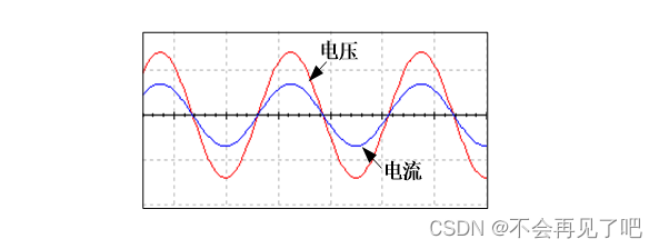
, The phase of the voltage is ahead of the phase of the current 90°, Pictured 1-2 Shown .
(3) capacitance C The relationship between the sinusoidal voltage at both ends and the sinusoidal current flowing through the capacitor conforms to the formula  , among
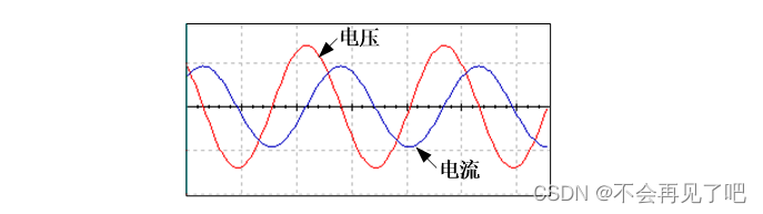
, The phase of voltage lags behind the phase of current 90°, Pictured 1-3 Shown .

5.4 Sampling resistance
In the experiment , When observing the phase relationship between the terminal voltage of a certain branch and the current flowing , It is necessary to measure the waveform of voltage and current . from
When the oscilloscope observes the waveform, it is connected in parallel at both ends of the measured Branch , therefore , The waveform of voltage can be easily observed by oscilloscope , And electricity
The waveform of the flow cannot be observed directly with an oscilloscope . The usual method is to string a small resistance sample into the measured Branch
Resistance , Convert the waveform of the measured current into a voltage waveform that changes according to the same law , Then use the double trace oscilloscope to observe at the same time .
6 Experiment content and steps
6.1 measurement R、L、C The phase relationship between voltage and current on the component
(1) stay “ Dynamic circuit research module ” On the board , According to the figure 1-4 Connect the experimental circuit . Connect the output end of the signal source with 1P04、
1P05、1P06 Connected to a , send R、L、C The components are respectively connected to the circuit ; among ,1L2=15mH,1C2=0.015mF,
1R3=1KW; In order to facilitate the measurement of current waveform , Connect a 20W Sampling resistance of 1R2;1R2 One end 1P03 Pick up
To GND;
(2)DDS The signal source output provides sinusoidal AC signal , Its frequency is 8kHz, Effective value of amplitude U = 1V( Use rivet hole line to DDS
The terminal is connected with the millivoltmeter terminal , adjustment DDS Signal source amplitude , Make the millivoltmeter read 1.00). Oscilloscope CH1 Of “+” Receive 1TP03
The test end ,“-” Receive 1P03 End , Measure the current passing through both ends of the inductor ; Oscilloscope CH2 Of “+” Terminate 1P04,“-” End suspension
Don't pick up , Measure the voltage across the inductor ; Oscilloscope trigger source selection CH2 Trigger , take CH1 Transfer to 100mV/Div,CH2 Transfer to
2V/Div; At this time, the phase relationship between the voltage at both ends of the inductance and the current flowing through the inductance can be observed on the oscilloscope , Measurement requires
Read out the number of cells occupied by a period of sinusoidal signal A, And the number of cells occupied by the phase difference of the two waveforms B. Fill the measurement data in the table
1-1.

(3) Map 1-4 Replace the inductance in with capacitance ( Signal source output DDS And 1P05 Connected to a , Oscilloscope CH2 Of “+” Terminate
1P05), Use a dual trace oscilloscope to observe the phase difference between the voltage at both ends of the capacitor and the current flowing through the capacitor . Fill the measurement data in the table
1-1.
(4) Map 1-4 Replace the capacitance in with resistance ( Signal source output DDS And 1P06 Connected to a , Oscilloscope CH2 Of “+” Terminate
1P06), Use a dual trace oscilloscope to observe the phase difference between the voltage at both ends of the resistance and the current flowing through the resistance . Finish the table 1-1.
explain : In the picture R=20Ω It is to provide sampling resistance for measuring current . In the experiments , Use the voltage waveform on the sampling resistance to replace the current
The current waveform of the tested component , It is convenient to measure the phase difference .
surface 1-1 R、L、C The phase difference between voltage and current on the component
Phase difference between voltage and current | electric sense | electric Rong | electric Resistance | ||
The reason is On value | |||||
Dual trace oscilloscope Measured value | B | ||||
A | |||||
Phase difference | |||||
Be careful : When measuring , To reduce the measurement error , Adjustable number of cells occupied by sine wave period A To be close to 10 The integer of , Then read the number of cells occupied by the difference between the two waveforms B.
2. Research RL Phase relationship between voltage and current in series circuit
(1) stay “ Dynamic circuit research module ” On the board , According to the figure 1-5 Connect the experimental circuit . Output the signal source DDS Receive
1P04,1P06 Receive GND; among ,1L2=15mH,1R3=1KW;
(2)DDS The signal source provides sinusoidal AC signal , Adjust its output frequency to 8kHz, Adjust its output amplitude to make the voltage effective value U =
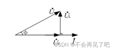
4V, Use an AC millivoltmeter to measure the voltage value on each component , Its vector diagram is shown in Figure 1-6 Shown , And calculate according to the measured value U、 Calculation
φ, Fill the measured data and calculated data in the table respectively 1-2.

(3) Measure the total voltage in the circuit with a dual trace oscilloscope U And total current I Phase difference of φ, Fill in the table 1-2.
surface 1-2 Study the phasor relationship between voltage and current
Measurement and calculation | The oscilloscope measures | |||||||
U | UR | UL | Calculation U | Calculation φ | A | B | measurement φ | |
Theoretical value | 4 V | |||||||
Measured value | ||||||||
3. Research RLC Phasor relation of series circuit
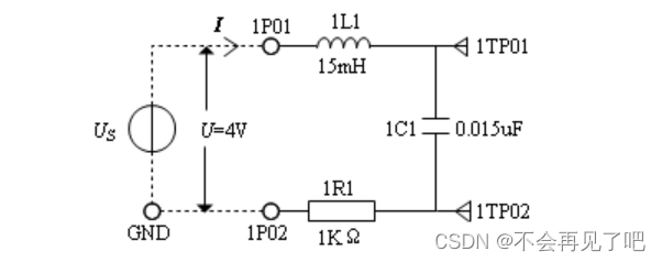
(1) stay “ Dynamic circuit research module ” Press the figure on the experimental board 1-7 Connect the circuit . Signal source output DDS Connect to 1P01,1P02
Receive GND;
(2) The adjustment method of the output amplitude of the signal source is the same as the previous experiment , The output frequency is adjusted to 8kHz and 15kHz, With AC milli
The voltmeter measures the voltage value of each component at two frequencies , Fill the measurement data in the table 1-3.
(2) The dual trace oscilloscope measures the total voltage in the series circuit U And total current I Phase difference of φ. Record the measured data in table 1-3 “ Oscilloscope measurement
The amount ” One column .
(3) According to the above circuit and the effective value data of each voltage measured by AC millivoltmeter , Calculate the total voltage U And total current I Phase difference of
φ, Fill in the table 1-3.
surface 1-3 Determination RLC A series circuit
f | AC millivoltmeter | The oscilloscope measures | |||||||
U | UR | UL | UC | Calculation U | Calculation φ | A | B | measurement φ | |
8kHz Theoretical value | 4V | —— | —— | —— | |||||
8kHz Measured value | |||||||||
15kHz Theoretical value | 4V | —— | —— | —— | |||||
15kHz Measured value | |||||||||
7 Experimental report and thinking questions
1. Write the experimental data table .
边栏推荐
- (Video + graphic) machine learning introduction series - Chapter 5 machine learning practice
- [leetcode] 1162 map analysis
- 【LeetCode】695-岛屿的最大面积
- Redux——详解
- 奥比中光 astra: Could not open “2bc5/[email protected]/6“: Failed to set USB interface
- 2279. 装满石头的背包的最大数量
- The outline dimension function application of small motherboard
- Bing.com网站
- 2279. Maximum number of backpacks filled with stones
- 03. Preliminary use of golang
猜你喜欢

全是精华的模电专题复习资料:基本放大电路知识点
![[salesforce] how to confirm your salesforce version?](/img/ce/4c844b1b686397faa1b6aa3d57e034.png)
[salesforce] how to confirm your salesforce version?

Leetcode skimming -- incremental ternary subsequence 334 medium
Redux——详解

2022 college students in Liaoning Province mathematical modeling a, B, C questions (related papers and model program code online disk download)
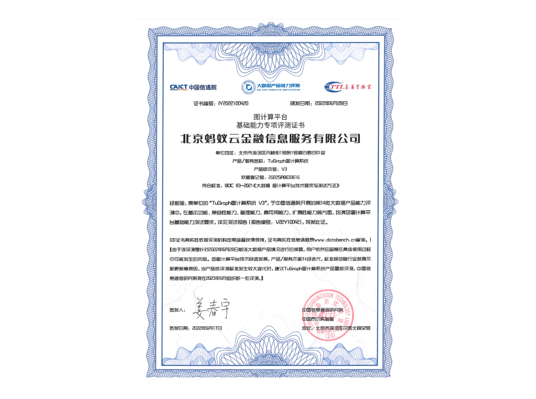
蚂蚁集团大规模图计算系统TuGraph通过国家级评测
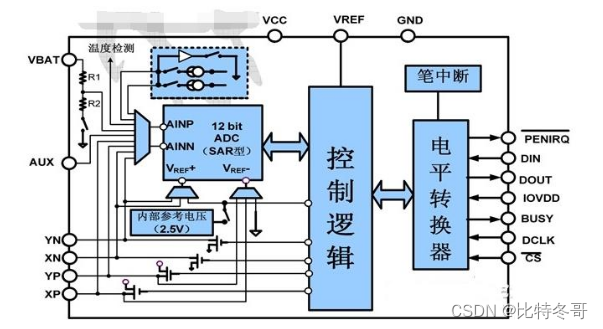
XPT2046 四线电阻式触摸屏
![[leetcode] 1254 - count the number of closed Islands](/img/84/f888ae0e164951cd9623fb3bf4a984.png)
[leetcode] 1254 - count the number of closed Islands

PTA ladder game exercise set l2-001 inter city emergency rescue

已知兩種遍曆序列構造二叉樹
随机推荐
Basic knowledge of cryptography
Name of institution approved in advance
Summary of the first three passes of sqli Labs
Finally, I understand the event loop, synchronous / asynchronous, micro task / macro task, and operation mechanism in JS (with test questions attached)
02. After containerization, you must face golang
/bin/ld: 找不到 -lxml2
MD5 encryption
Redux - detailed explanation
将点云坐标转换成世界坐标的demo
[leetcode] 1905 statistics sub Island
全是精华的模电专题复习资料:基本放大电路知识点
愛可可AI前沿推介(7.2)
【Leetcode】167-两数之和II -输入有序数组
数字藏品系统开发(程序开发)丨数字藏品3D建模经济模式系统开发源码
locate: 无法执行 stat () `/var/lib/mlocate/mlocate.db‘: 没有那个文件或目录
高考录取分数线爬虫
SQL transaction
College entrance examination score line climbing
Comparison between rstan Bayesian regression model and standard linear regression model of R language MCMC
Wechat Alipay account system and payment interface business process