Introduction
The thought of original text There are references to course , I went to see , Find it helpful to understand some logic , By the way, translate and record .
- original text :A GPU Approach to Particle Physics
- Origin
- My GitHub
Text
my GPGPU The next project in the series is a particle physics engine , It's in GPU Calculate the whole physical simulation . Particles affected by gravity , Will bounce with the scene geometry . This WebGL Demonstrates the use of shader functionality , There is no need to strictly follow OpenGL ES 2.0 Specification requirements , So it may not work on some platforms , Especially on mobile devices . This will be discussed later in this article .
It is interactive . The mouse cursor is a circular obstacle that causes particles to bounce , Click to place a permanent obstacle in the simulation . You can draw structures through which particles can flow .
This is an example of HTML5 Video shows , Out of necessity , It's in seconds 60 High bit rate recording of frames , So it's pretty big . The video codec can't handle all the particles on the full screen very well , Lower frame rates don't capture well . I also added some sounds that I wouldn't hear in the actual Demo .
- Video address :https://nullprogram.s3.amazon...
In modern times GPU On , It can run in seconds 60 Frame speed simulation also Draw more than 4 Millions of particles . please remember , This is a JavaScript Applications , I didn't really spend time optimizing shaders , It receives WebGL Constraints , Not like it OpenCL Or at least the desktop OpenGL This is more suitable for general calculation .
The particle state is encoded in color
It's like Game of Life and path finding Same project , Simulation states are stored in pairs of textures , Most of the work is done in the slice shader through the pixel by pixel mapping between them . I won't repeat this setup detail , So if you need to understand how it works , Please refer to Game of Life One article .
For this simulation , There are four of these textures, not two : A pair of position textures and a pair of velocity textures . Why pairs of textures ? Yes 4 Channels , So every part of it (x、y、dx、dy) Can be packaged into their own color channel . This seems to be the simplest solution .

The problem with this scheme is the lack of accuracy . about R8G8B8A8 Internal texture format , Each channel is one byte . All in all 256 Possible values . The display area is 800×600 Pixels , Therefore, each position on the display area cannot be displayed . Fortunately, , Two bytes ( A total of 65536 It's worth ) It's enough for us .


The next question is how to encode values across these two channels . It needs to override negative values ( Negative velocity ), The dynamic range shall be fully utilized , For example, try to use all 65536 Values in the range .
To encode a value , Multiply the value by a scalar , Extend it to the dynamic range of encoding . When selecting a scalar , The highest value required ( The size of the display ) Is the highest value of the code .
Next , Add half of the dynamic range to the scale value . This converts all negative values to positive values ,0 Represents the minimum value . This representation is called Excess-K . The disadvantage is to clear the texture with transparent black (glClearColor) The decode value cannot be set to 0 .
Last , Treat each channel as having a cardinality of 256 The number of .OpenGL ES 2.0 Shader languages do not have bitwise operators , So this is done using ordinary division and modulo . I use JavaScript and GLSL An encoder and decoder are made .JavaScript You need it to write the initial value , And for debugging purposes , It can read back the particle position .
vec2 encode(float value) {
    value = value * scale + OFFSET;
    float x = mod(value, BASE);
    float y = floor(value / BASE);
    return vec2(x, y) / BASE;
}

float decode(vec2 channels) {
    return (dot(channels, vec2(BASE, BASE * BASE)) - OFFSET) / scale;
}
JavaScript With the above standardization GLSL value (0.0-1.0) Different , This generates an integer of one byte (0-255), Used to package into a typed array .
function encode(value, scale) {
    var b = Particles.BASE;
    value = value * scale + b * b / 2;
    var pair = [
        Math.floor((value % b) / b * 255),
        Math.floor(Math.floor(value / b) / b * 255)
    ];
    return pair;
}

function decode(pair, scale) {
    var b = Particles.BASE;
    return (((pair[0] / 255) * b +
             (pair[1] / 255) * b * b) - b * b / 2) / scale;
}
Update the slice shader of each particle in the “ Indexes ” Position and velocity textures are sampled at , Decode their values , Operate them , Then code them back to a color , To write the output texture . Because I use WebGL , It is missing multiple render targets ( In spite of the support gl_FragData ), So the slice shader can only output one color . The location is updated in a process , The speed is updated to two separate plots in another process . The buffer is completed in two processes after Will exchange , So the velocity shader ( deliberately ) The updated position value will not be used .
There is a limit to the maximum texture size , Usually it is 8192 or 4096 , So the texture is not arranged in one dimension , But keep it square . Particles are indexed by two-dimensional coordinates .
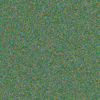
It's interesting to see a position or velocity texture painted directly on the screen instead of being displayed normally . This is another area for viewing simulations , It even helped me find some problems that are difficult to see in other aspects . The output is a set of blinking colors , But there are clear patterns , Shows many states of the system ( Or not in it ). I want to share a video , But coding is more impractical than normal display . Here is the screenshot : Location , Then there's speed . There is no alpha component captured here .

State to keep
stay GPU One of the biggest challenges of running such simulations on is the lack of random values . There is no... In the shader language rand() function , So the whole process is deterministic by default . All States come from CPU The initial texture state of the fill . When particles gather and match States , Maybe it's going through an obstacle together , It's hard to separate them , Because the simulation treats them the same way .
To alleviate the problem , The first rule is to keep the state as much as possible . When a particle leaves the bottom of the display area , It will be moved back to the top for “ Reset ”. If the Y Value is set to 0 To do this , Then the information will be destroyed . This must be avoided ! Despite exiting during the same iteration , But show particles below the bottom edge Y Values tend to vary slightly . Replace reset to 0 To add a constant : The height of the display area .Y The values are still different , Therefore, these particles are more likely to follow different routes when colliding with obstacles .
The next technique I use is through uniform Provide a new random value for each iteration , This value is added to reset the position and speed of the particles . The same value is used for all particles for that particular iteration , So this doesn't help the overlapping particles , But it helps to separate “ flow ”. These are clearly visible particle lines , All follow the same path . Each exits the bottom of the display in a different iteration , So random values separate them slightly . Final , This adds some new states to the simulation for each iteration .
perhaps , You can provide shaders with textures that contain random values .CPU You must always fill and upload textures , In addition, there is the problem of selecting the texture sampling location , The texture itself needs a random value .
Last , To deal with completely overlapping particles , Scales the unique two-dimensional index of the particles on reset , And add it to position and speed , To separate them . Multiply the sign of the random value by the index , To avoid deviation in any particular direction .
To see all this in the demo , Make a big circle to capture all the particles , Let them flow into a point . This will remove all States from the system . Now clear the obstacles . They all turn into a tight mass . On top reset , It will still have some aggregation , But you'll see them slightly apart ( Added particle index ). They will leave the bottom at slightly different times , So random values play a role , Make them more separate . After a few rounds , The particles should be evenly distributed again .
The last source of status is your mouse . When you move it in the scene , Will interfere with particles , And introduce some noise into the simulation .
Texture as vertex attribute buffer
In the reading OpenGL ES Shader Language Specification (PDF) when , I came up with the idea of this project . I've always wanted to build a particle system , But I'm stuck in how to draw particles . The texture data representing the position needs to be fed back to the pipeline as vertices in some way . Usually , Buffer texture —— Textures supported by array buffers —— or Pixel buffer object —— Asynchronous texture data replication —— Can be used for this operation , but WebGL Without these functions . from GPU Extract texture data from , It is impossible to reload it as an array buffer on each frame .
However , I came up with a cool trick , Better than these two . Shader functions texture2D Used to sample pixels in a texture . Usually , The slice shader uses it as part of the process of calculating the color of a pixel . But the Shader Language Specification mentions ,texture2D You can also use... In vertex shaders . Just then , An idea hit me . The vertex shader itself can perform the conversion from texture to vertex .
It works by passing the previously mentioned two-dimensional particle index as a vertex attribute , Use them to find particle positions from vertex shaders . Shaders will be rendered in GL_POINTS mode , Emission point particles . This is a simplified version :
attribute vec2 index;

uniform sampler2D positions;
uniform vec2 statesize;
uniform vec2 worldsize;
uniform float size;

// float decode(vec2) { ...

void main() {
    vec4 psample = texture2D(positions, index / statesize);
    vec2 p = vec2(decode(psample.rg), decode(psample.ba));
    gl_Position = vec4(p / worldsize * 2.0 - 1.0, 0, 1);
    gl_PointSize = size;
}
The real version will also sample the speed , Because it will adjust the color ( Slow moving particles are brighter than fast moving particles ).
However , There is a potential problem : Allows implementation to limit the number of vertex shader texture bindings to 0(GL_MAX_vertex_texture_IMAGE_UNITS). So technically , Vertex shaders must always support texture2D , But they don't need to support actual textures . It's a bit like an empty catering service on an airplane . Some platforms do not support this technology . up to now , I have only experienced this problem on some mobile devices .
In addition to the lack of some platform support , This allows every part of the simulation to remain GPU On , And pure GPU Particle systems pave the way .
obstacle
An important observation is that there is no interaction between particles . This is not a n Body simulation . However , They do interact with the rest of the world : They bounce intuitively from these stationary circles . The environment is represented by another texture , The texture does not update during normal iterations . I call it obstacle texture .
The color on the obstacle texture is the surface normal . in other words , Each pixel has a direction that points to it , A flow that directs particles in a certain direction . The gap has a special constant (0,0). This is not a unit vector ( The length is not 1), So it is an out of band value that has no effect on the particles .
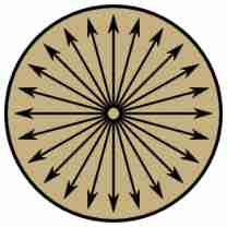
Particles only need to sample the obstacle texture to check for collisions . If you find the normal at its location , Then use the shader function reflect Change its speed . This function is usually used in 3D Reflected light in the scene , But the same applies to slow-moving particles . The effect is that the particles bounce off the circle in a natural way .
Sometimes particles fall on or in obstacles at low or zero speed . In order to remove them from obstacles , Will push them gently in the normal direction . You will see this on the slope , There? , The slow particles move down freely like jumping beans .
In order to make the obstacle texture user-friendly , The actual geometry is in JavaScript Of CPU End for maintenance . These circles will remain in a list , And when updating , Redraw the obstacle texture in this list . for example , Every time you move the mouse over the screen , It happens all the time , Thus, moving obstacles are generated . Textures provide shader friendly access to geometry . The two manifestations have two purposes .
When I started writing this part of the program , I envision other shapes that can be placed besides circles . for example , Solid rectangle : The normal looks like this .
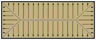
up to now , These have not yet been implemented .
Future ideas
I haven't tried , But I wonder if particles can also interact by painting themselves onto an obstacle texture . Two nearby particles will bounce off each other . Maybe the whole liquid demo Can be like this in GPU Up operation . If my guess is correct , The particles increase in size , A bowl shaped obstacle will fill , Instead of focusing the particles on a single point .
I think this project still has some places to explore .

![Optical blood pressure estimation based on PPG and FFT neural network [translation]](/img/88/2345dac73248a5f0f9fa3142ca0397.png)

![[matlab] Simulink the input and output variables of the same module cannot have the same name](/img/99/adfe50075010916439cd053b8f04c7.png)
