当前位置:网站首页>Canoe - the second simulation engineering - xvehicle - 2panel design (principle, idea)
Canoe - the second simulation engineering - xvehicle - 2panel design (principle, idea)
2022-07-04 10:50:00 【picoasis】
Catalog
How—— Design / To configure Panel Control
Xvehicle In Engineering Panel Design process
Project description
Simulation Engineering X-Vehicle:
The project includes three ECU:Engine、Door and Display.
adopt Control Panel to simulate engine state switching 、 Speed adjustment and door Switch operation , At the same time Display The relevant status is displayed on the panel .
Previous review
Operate in the previous article (CANoe- The first 2 A simulation project -XVehicle—1 Bus database design ( Ideas )_lamanchas The blog of -CSDN Blog ) in , We define the data in the database , Created XVehicle Each part of the project ECU( door , engine , Monitor )、CAN Bus 、 Signals needed for communication 、 message 、 Variable , And the correlation between communication signals and communication nodes . As shown in the figure below :
| Communication nodes ——ECU | 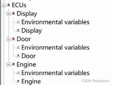 |
| Communication message —— environment variable | |
| Communication message —— message | 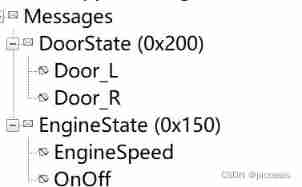 |
| Communication message —— The signal | 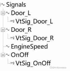 |
| Communication network —— structure | 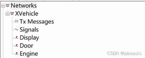 |
Communication network —— Communication nodes | |
Communication network —— Of each communication node Signal receiving and sending | 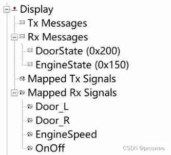  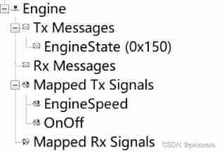 |
Why— Panel design
thus ECU Communication definition completed , What this section does is : Realize simulation Control and Display panel .
Complete the definition of communication network , Next, we need to communicate on the network .
The process of communication involves signal transmission , The received signal shows the state change . So how to make each ECU Signal , And how to make ECU Show your state changes after the signal is sent , Today's main work —— Panel design .
The panel is mainly in the form of visual controls , Simulate components . This is for the operation of components , The status display of components will be more intuitive .
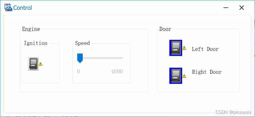
such as , Switch this part ( stay panel It is called a control in ), stay panel As shown in the figure below , By configuring its properties , It can be completed by clicking the mouse ‘ open ’ Signals and ‘ Turn off ’ The transmission of signals . Drag and drop Speed Control's slider , Change the engine speed .
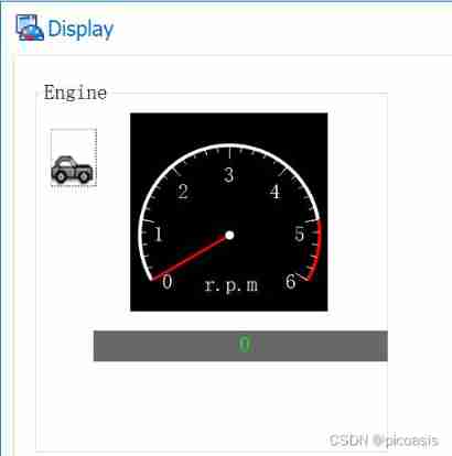
And such as , Dashboard control , After the engine receives the corresponding signal , It can visually display the current speed .
What—— Panel design
By the example above , We can find out , Switches and dashboards , One is signaling , One is to show the signal . This is also one of the control classification standards in the panel .
Controls can be divided by control and display 2 Kind of : Control controls 、 Display controls .
among , Control controls , Used to correlate signals 、 System variables 、 environment variable .
Display controls , For real-time display The signal 、 Variable 、 The value of the diagnostic parameter .
The main controls are :
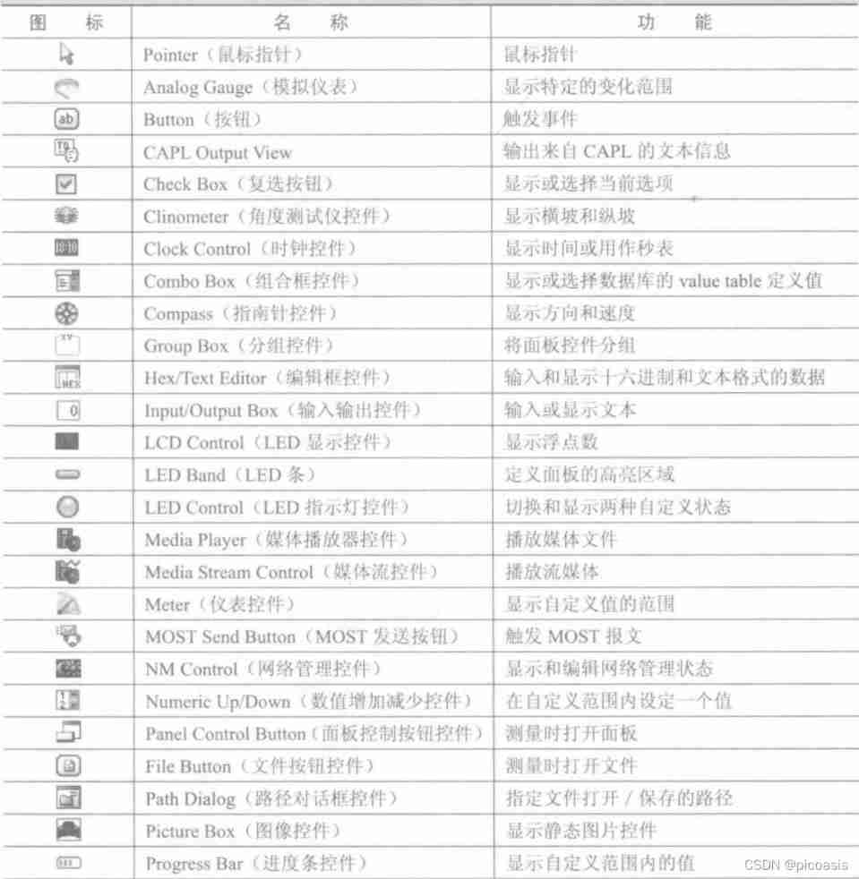

A detailed explanation of the control functions can be found below : CANoe And Panel Designer Use (CANoe Series II )_ The first 55 Little white duck's blog -CSDN Blog _canoe panel panel
How—— Design / To configure Panel Control
Panel Control configuration has two important parts :
One is , Configure the control's own properties , Such as display style , typeface , Signal format ( Value range , step ); If it is a control control , that There are also control methods ( For example, what kind of mouse operation does the switch control use , On behalf of 、 Turn off ); If it is a display control , Then configure the display image ( Such as door status , When receiving the signal of opening the left door , Use picture presentation )
The other is to select the control to associate Symbol.Panel Controls and these Symbol Connected to a , signify Panel Control is connected to the previously defined communication network :Panel Control will be from these Symbol Get the information you need , Or to these Symbol Write the information you want to send . The specific implementation of sending and receiving is through ECU Upper CAPL Programming to realize , It will be described in the next section ( Write a link here ).
among Symbol There are two types of : One is Signal, One is Variable. After selecting the type to associate , And then Symbol Select the specific variables in this type to associate .
PS:Variable It also includes environment variables 、 System variables . environment variable It is related to the project dbc Created in the , and System variables Is in CANoe Project toolbar Environment Under the System Variables Created in the .( The functional difference between the two is also a point , Preemptive pit , Write a link and put it here )
Xvehicle In Engineering Panel Design process
The steps are summarized as follows :
- Add system variables ——SystemEnvironment——NameSpace:Engine(EngineStateSwitch,EnginSpeedDspMeter,EngineSpeedEntry)
- add to Control panel ——Panel Add the control in charge of control ( Door control , Engine control )
- add to Display panel ——Panel Add the control responsible for display ( Door display , Engine display )
- establish Desktop—— Create a new one DeskTop Tab , hold control Panel window ,Display Panel window ,write window ,Trace Put the windows together , Easy to test and observe .
Please move the specific steps (https://blog.csdn.net/lamanchas/article/details/122168798)
Result——Panel Design
After the above steps are completed , The control and display panel is defined , And connected to the communication network .
Then we can use the graphical interface , It is very convenient to change the value of signal or variable , And visually check the output status of the system .
END
边栏推荐
- 1. Circular nesting and understanding of lists
- 2022 ape circle recruitment project (software development)
- /*Write a loop to output the elements of the list container in reverse order*/
- For and while loops
- Dichotomy search (C language)
- 2、 Operators and branches
- /*Rewrite the program, find the value of the element, and return the iterator 9.13: pointing to the found element. Make sure that the program works correctly when the element you are looking for does
- VI text editor and user rights management, group management and time management
- system design
- [test theory] test process management
猜你喜欢

BGP ---- border gateway routing protocol ----- basic experiment
Hidden C2 tunnel -- use of icmpsh of ICMP

Summary of several job scheduling problems

TS type gymnastics: illustrating a complex advanced type
Postman interface test
Virtual machine configuration network
![[Galaxy Kirin V10] [server] NUMA Technology](/img/9b/65466c6fc6336e27e842f50c26b9c3.jpg)
[Galaxy Kirin V10] [server] NUMA Technology
DML statement of MySQL Foundation
Huge number (C language)
When I forget how to write SQL, I
随机推荐
[Galaxy Kirin V10] [server] FTP introduction and common scenario construction
[Galaxy Kirin V10] [server] set time synchronization of intranet server
[Galaxy Kirin V10] [server] system startup failed
Application and Optimization Practice of redis in vivo push platform
Collection of practical string functions
C language - stack
[testing theory] thinking about testing profession
[test theory] test process management
Rhcsa12
Using Lua to realize 99 multiplication table
Jianzhi offer 04 (implemented in C language)
Write a program to judge whether the two arrays are equal, and then write a similar program to compare the two vectors.
Es entry series - 6 document relevance and sorting
Knapsack problem and 0-1 knapsack problem
[test theory] test the dimension of professional ability
Installation of ES plug-in in Google browser
OSPF summary
Jemeter script recording
Velodyne configuration command
Performance test method