当前位置:网站首页>Design of digital video signal processor based on FPGA (with main code)
Design of digital video signal processor based on FPGA (with main code)
2022-06-27 15:25:00 【FPGA technology Jianghu】
Hello, great Xia , Welcome to FPGA Technical Jianghu , The world is so big , Meeting is fate .
Today, I bring you FPGA Digital video signal processor design , Because of the long space , It is divided into three parts . Today brings the third , The next part , Program testing and running . Don't talk much , Loading .
Here are the first two hyperlinks . as follows :
be based on FPGA Digital video signal processor design ( On )
be based on FPGA Digital video signal processor design ( in )
There have been articles on image processing before , Here are some hyperlinks , For your reference .
selections :FPGA Image processing of design experience
be based on FPGA Real time image edge detection system design ( Next )
FPGA In design Verilog HDL Realize the basic image filtering processing simulation
Reading guide
Images are obtained by observing the objective world in different forms and means with various observation systems , An entity that can act directly or indirectly on the human eye to produce visual perception .
With the rapid development of electronic technology and computer technology , Digital image technology has received great attention and considerable development in recent years , And in scientific research 、 industrial production 、 medical and health work 、 Communication has been widely used .
The video signal consists of a series of continuous images . The processing of video signal has become an important part in the field of digital image processing . For example, the process of robot pattern recognition is a process of video signal processing , The target recognition of TV guided missile is to make full use of video signal processing technology to continuously judge whether the target is consistent with the preset target image . This article will explain how to use FPGA Technology to achieve basic video signal processing . The example of this article can be used as a reference for video signal processing , It can also be extended as needed on this basis .
Part three content summary : This chapter will introduce program testing and running , Including test procedures 、 Test results and summary .
5、 ... and 、 Program testing and running
Because of the whole FPGA The program includes 3 part : be in TOP Main procedure of , Control the operation of other parts of the program ; Video image data acquisition program , from SAA7113 Obtain digital image data and save it to SRAM in ;SRAM Read and write program to achieve SRAM Reading and writing data of . The test program needs the whole process of simulation data .
5.1 The test program
The test program code is as follows :
`include "timescale.v"
moduletst_saa7113(error,dsprst,xreset,saareset,ARDY,ED_O,ED_OEN_O,SRAM_1_EA,SRAM_2_EA,SRAM_1_O_ED,SRAM_2_O_ED);
    // Internal register
    reg reset;
    reg clk;//50MHz  The clock
    reg llck;//SAA7113  The clock of
    reg [7:0] vpo;// come from  saa7113  Image data
    reg capture;// Acquisition data flag
    reg toggle;// Bus switching flag
    reg [1:0] rst;

    // Input
    input error;
    input dsprst,xreset,saareset;
    input ARDY;
    input [7:0] ED_O;
    input ED_OEN_O;
    input [18:0] SRAM_1_EA;
    input [7:0] SRAM_1_O_ED;
    input [18:0] SRAM_2_EA;
    input [7:0] SRAM_2_O_ED;

    // come from  dsp  The signal of
    reg CE3_;
    reg ARE_;
    reg AWE_;
    reg [21:2] EA;
    reg [7:0] ED_I;

    //TO SRAM
    reg [7:0] SRAM_1_IN_ED;
    reg [7:0] SRAM_2_IN_ED;

    //wires
    //from saa7113
    wire SRAM_CE_;
    wire SRAM_OE_;
    wire SRAM_WE_;
    wire [18:0] la;
    wire [7:0] ld;

    //FROM DSP
    wire CE_SRAM;
    wire WE_SRAM;
    wire OE_SRAM;
    wire [7:0] ED_SRAM;
    wire [18:0] EA_SRAM;

    // Connect the subroutines
    LWBSAA7113 L_SAA7113 (
                          .reset(reset),
                          .clk(clk),
                          .llck(llck),
                          .vpo(vpo),
                          .rst(rst),
                          .capture(capture),
                          .error(error),
                          .SRAM_CE_(SRAM_CE_),
                          .SRAM_OE_(SRAM_OE_),
                          .SRAM_WE_(SRAM_WE_),
                          .la(la),
                          .ld(ld)
                      );

    LWBDECODE L_DECODE (
                        .reset(reset),
                        .CE3_(CE3_),
                        .ARE_(ARE_),
                        .AWE_(AWE_),
                        .EA(EA),
                        .ED_I(ED_I),
                        .ED_O(ED_O),
                        .ED_OEN_O(ED_OEN_O),
                        .ARDY(ARDY),
                        .EA_SRAM(EA_SRAM),
                        .ED_SRAM(ED_SRAM),
                        .CE_SRAM(CE_SRAM),
                        .WE_SRAM(WE_SRAM),
                        .OE_SRAM(OE_SRAM),
                        .dsprst(dsprst),
                        .xreset(xreset),
                        .saareset(saareset)
                    );

    LWBBUSCHANGE L_BUSCHANGE (
                              .EA_SRAM(EA_SRAM),
                              .ED_SRAM(ED_SRAM),
                              .CE_SRAM(CE_SRAM),
                              .WE_SRAM(WE_SRAM),
                              .OE_SRAM(OE_SRAM),
                              .la(la),
                              .ld(ld),
                              .SRAM_CE_(SRAM_CE_),
                              .SRAM_WE_(SRAM_WE_),
                              .SRAM_OE_(SRAM_OE_),
                              .SRAM_1_IN_ED(SRAM_1_IN_ED),
                              .SRAM_2_IN_ED(SRAM_2_IN_ED),
                              .toggle(toggle),
                              .SRAM_1_EA(SRAM_1_EA),
                              .SRAM_1_O_ED(SRAM_1_O_ED),
                              .SRAM_2_EA(SRAM_2_EA),
                              .SRAM_2_O_ED(SRAM_2_O_ED)
                          );
    // Generate a clock signal
    always #10 clk=~clk;
    always #20 llck = ~llck;
    initial
        begin
            $display("\n status : %t TestBench of saa7113 started! \n\n",$time);

            //initial value
            clk = 0;
            #7;
            llck =0;

            //reset
            reset = 1;

            //dsp  initialization
            ARE_ = 1;
            AWE_ = 1;
            CE3_ = 1;

            // initialization
            capture = 0;
            toggle = 1;
            #2;
            reset = 0;
            repeat(20) @(posedge clk);
            reset = 1'b1; // negate reset

            //dsp  Read data content
            SRAM_1_IN_ED = 8'h1d;
            SRAM_2_IN_ED = 8'h2d;

            //dsp  Address bus
            EA[21:16] = 6'b000000;
            EA[15:7] = 9'b000000000;
            EA[6:2]= 5'b00001;
            #5;
            CE3_ = 0;
            ARE_ = 0;
            //saa7113  Output content
            capture = 1;
            #5;
            @(posedge llck) vpo = 8'haa;
            @(posedge llck) vpo = 8'hbb;
            @(posedge llck) vpo = 8'hcc;
            @(posedge llck) vpo = 8'hdd;
            @(posedge llck) vpo = 8'hee;

            // Field synchronization signal
            //1
            @(posedge llck) vpo = 8'hff;//begin
            @(posedge llck) vpo = 8'h00;
            @(posedge llck) vpo = 8'h00;
            @(posedge llck) vpo = 8'b00100000;//sav

            //2
            @(posedge llck) vpo = 8'hff;//begin
            @(posedge llck) vpo = 8'h00;
            @(posedge llck) vpo = 8'h00;
            @(posedge llck) vpo = 8'b00100000;

            // Data start
            @(posedge llck) vpo = 8'hff;//begin
            @(posedge llck) vpo = 8'h00;
            @(posedge llck) vpo = 8'h00;
            @(posedge llck) vpo = 8'b00000000;

            //data
            @(posedge llck) vpo = 8'h01;//Cb
            @(posedge llck) vpo = 8'h02;//Yb
            @(posedge llck) vpo = 8'h03;//Cr
            @(posedge llck) vpo = 8'h04;//Yr--1

            @(posedge llck) vpo = 8'h05;//Cb
            @(posedge llck) vpo = 8'h06;//Yb
            @(posedge llck) vpo = 8'h07;//Cr
            @(posedge llck) vpo = 8'h08;//Yr--2

            @(posedge llck) vpo = 8'h09;//Cb
            @(posedge llck) vpo = 8'h0a;//Yb
            @(posedge llck) vpo = 8'h0b;//Cr
            @(posedge llck) vpo = 8'h0c;//Yr--3

            @(posedge llck) vpo = 8'h0d;//Cb
            @(posedge llck) vpo = 8'h0e;//Yb
            @(posedge llck) vpo = 8'h0f;//Cr
            @(posedge llck) vpo = 8'h10;//Yr--4

            @(posedge llck) vpo = 8'h11;//Cb
            @(posedge llck) vpo = 8'h12;//Yb
            @(posedge llck) vpo = 8'h13;//Cr
            @(posedge llck) vpo = 8'h14;//Yr--5

            @(posedge llck) vpo = 8'h15;//Cb
            @(posedge llck) vpo = 8'h16;//Yb
            @(posedge llck) vpo = 8'h17;//Cr
            @(posedge llck) vpo = 8'h18;//Yr--6

            @(posedge llck) vpo = 8'h19;//Cb
            @(posedge llck) vpo = 8'h1a;//Yb
            @(posedge llck) vpo = 8'h1b;//Cr
            @(posedge llck) vpo = 8'h1c;//Yr--7

            @(posedge llck) vpo = 8'h1d;//Cb
            @(posedge llck) vpo = 8'h1e;//Yb
            @(posedge llck) vpo = 8'h1f;//Cr
            @(posedge llck) vpo = 8'h20;//Yr--8

            @(posedge llck) vpo = 8'h21;//Cb
            @(posedge llck) vpo = 8'h22;//Yb
            @(posedge llck) vpo = 8'h23;//Cr
            @(posedge llck) vpo = 8'h24;//Yr--9

            @(posedge llck) vpo = 8'h25;//Cb
            @(posedge llck) vpo = 8'h26;//Yb
            @(posedge llck) vpo = 8'h27;//Cr
            @(posedge llck) vpo = 8'h28;//Yr--10

            @(posedge llck) vpo = 8'h29;//Cb
            @(posedge llck) vpo = 8'h3a;//Yb
            @(posedge llck) vpo = 8'h3b;//Cr
            @(posedge llck) vpo = 8'h3c;//Yr--11

            // End of data
            @(posedge llck) vpo = 8'hff;//ff
            @(posedge llck) vpo = 8'h00;//00
            @(posedge llck) vpo = 8'h00;//00
            @(posedge llck) vpo = 8'b01110000;//end of field 1

            #20;
            ARE_ = 1;
            capture = 0;
            #200;

            // Start switching
            toggle = 0;
            #100;
            ARE_ = 0;

            // Start collecting data
            capture = 1;

            //vertical blanking stage
            //1
            @(posedge llck) vpo = 8'hff;//begin
            @(posedge llck) vpo = 8'h00;
            @(posedge llck) vpo = 8'h00;
            @(posedge llck) vpo = 8'b00100000;//sav

            //2
            @(posedge llck) vpo = 8'hff;//begin
            @(posedge llck) vpo = 8'h00;
            @(posedge llck) vpo = 8'h00;
            @(posedge llck) vpo = 8'b00100000;

            //data start
            @(posedge llck) vpo = 8'hff;//begin
            @(posedge llck) vpo = 8'h00;
            @(posedge llck) vpo = 8'h00;
            @(posedge llck) vpo = 8'b00000000;

            //data
            @(posedge llck) vpo = 8'h01;//Cb
            @(posedge llck) vpo = 8'h02;//Yb
            @(posedge llck) vpo = 8'h03;//Cr
            @(posedge llck) vpo = 8'h04;//Yr--1

            @(posedge llck) vpo = 8'h05;//Cb
            @(posedge llck) vpo = 8'h06;//Yb
            @(posedge llck) vpo = 8'h07;//Cr
            @(posedge llck) vpo = 8'h08;//Yr--2

            @(posedge llck) vpo = 8'h09;//Cb
            @(posedge llck) vpo = 8'h0a;//Yb
            @(posedge llck) vpo = 8'h0b;//Cr
            @(posedge llck) vpo = 8'h0c;//Yr--3

            @(posedge llck) vpo = 8'h0d;//Cb
            @(posedge llck) vpo = 8'h0e;//Yb
            @(posedge llck) vpo = 8'h0f;//Cr
            @(posedge llck) vpo = 8'h10;//Yr--4

            @(posedge llck) vpo = 8'h11;//Cb
            @(posedge llck) vpo = 8'h12;//Yb
            @(posedge llck) vpo = 8'h13;//Cr
            @(posedge llck) vpo = 8'h14;//Yr--5

            @(posedge llck) vpo = 8'h15;//Cb
            @(posedge llck) vpo = 8'h16;//Yb
            @(posedge llck) vpo = 8'h17;//Cr
            @(posedge llck) vpo = 8'h18;//Yr--6

            @(posedge llck) vpo = 8'h19;//Cb
            @(posedge llck) vpo = 8'h1a;//Yb
            @(posedge llck) vpo = 8'h1b;//Cr
            @(posedge llck) vpo = 8'h1c;//Yr--7

            @(posedge llck) vpo = 8'h1d;//Cb
            @(posedge llck) vpo = 8'h1e;//Yb
            @(posedge llck) vpo = 8'h1f;//Cr
            @(posedge llck) vpo = 8'h20;//Yr--8

            @(posedge llck) vpo = 8'h21;//Cb
            @(posedge llck) vpo = 8'h22;//Yb
            @(posedge llck) vpo = 8'h23;//Cr
            @(posedge llck) vpo = 8'h24;//Yr--9

            @(posedge llck) vpo = 8'h25;//Cb
            @(posedge llck) vpo = 8'h26;//Yb
            @(posedge llck) vpo = 8'h27;//Cr
            @(posedge llck) vpo = 8'h28;//Yr--10

            @(posedge llck) vpo = 8'h29;//Cb
            @(posedge llck) vpo = 8'h3a;//Yb
            @(posedge llck) vpo = 8'h3b;//Cr
            @(posedge llck) vpo = 8'h3c;//Yr--11

            // End of data
            @(posedge llck) vpo = 8'hff;//ff
            @(posedge llck) vpo = 8'h00;//00
            @(posedge llck) vpo = 8'h00;//00
            @(posedge llck) vpo = 8'b01110000;//end of field 1
            #20;

            // End data collection
            capture = 0;

            #200;
            // End of test procedure
            $finish;
        end
endmodule
5.2 test result
The video image data generated by the simulation program is shown in the figure 18 Shown . At the beginning “aa bb cc dd ee ff” Is invalid data ,“ff 00 20” Indicates the field synchronization signal .
chart 18 Video image data generated by simulation
after FPGA After processing, the effective image data is obtained and the corresponding address signal is generated , Pictured 19 Shown . Because only gray operation is carried out , Take only brightness information , Therefore, the data obtained is “04 08 0c”, At the same time, an address signal is generated “00 01 02”.
chart 19 FPGA Collect the effective image data and generate the address signal
Yes SRAM Read and write control , Pictured 20 Shown .
chart 20 The result is right SRAM Read and write control
Two pieces of SRAM Switch between , Pictured 21 Shown .
chart 21 Two pieces of SRAM Switch between
The simulation results show that the whole video signal processing program has completed the preset design goal .
7、 ... and 、 summary
边栏推荐
- E-week finance Q1 mobile banking has 650million active users; Layout of financial subsidiaries in emerging fields
- my. INI file configuration
- Use GCC to generate an abstract syntax tree "ast" and dump it to Dot file and visualization
- [an Xun cup 2019]attack
- Design and implementation of reading app based on Web Platform
- February 16, 2022 freetsdb compilation and operation
- Computer screen splitting method
- 漏洞复现----34、yapi 远程命令执行漏洞
- Programming skills: script scheduling
- Design skills of main function of Blue Bridge Cup single chip microcomputer
猜你喜欢

Semaphore of thread synchronization

Reflection learning summary

阅读别人的代码,是一种怎样的体验

Pycharm安装与设置

Teach you how to realize pynq-z2 bar code recognition
基于SSM的Web网页聊天室系统

SQL parsing practice of Pisa proxy

volatile与JMM
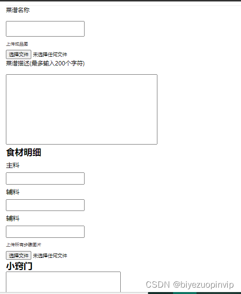
Design and implementation of food recipe and ingredients website based on vue+node+mysql

Leetcode 724. Find the central subscript of the array (yes, once)
随机推荐
Leetcode 724. 寻找数组的中心下标(可以,一次过)
Multithreading Basics (III)
CAS comparison and exchange
我想买固收+产品,但是不了解它主要投资哪些方面,有人知道吗?
Piblup test report 1- pedigree based animal model
Use of abortcontroller
老师能给我说一下固收+产品主要投资于哪些方面?
In the past, domestic mobile phones were arrogant in pricing and threatened that consumers would like to buy or not, but now they have plummeted by 2000 for sale
2022-2-15 learning the imitated Niuke project - Section 5 shows comments
Jupiter core error
Leetcode 724. Find the central subscript of the array (yes, once)
Teach you how to package and release the mofish Library
CNN convolutional neural network (the easiest to understand version in History)
Interview question: rendering 100000 data solutions
Redis CacheClient
Experience sharing of mathematical modeling: comparison between China and USA / reference for topic selection / common skills
Fundamentals of software engineering (I)
Admixture usage document Cookbook
16 -- 删除无效的括号
Interpretation of new version features of PostgreSQL 15 (including live Q & A and PPT data summary)