当前位置:网站首页>IIC communication protocol (I)
IIC communication protocol (I)
2022-07-27 04:38:00 【On the way, starting】

Catalog
1.2、 Write sequence consecutively
2.2、 Continuous reading sequence
introduction
This column has been idle for a long time , I've been taking time off recently and want to learn IIC Communication protocol and corresponding FPGA Realization . By the way, record it in the form of blog ~
This blog post mainly introduces and IIC Basic content related to communication .
IIC agreement
1、 history
IIC The bus was developed by Philips in the last century 80 Bus protocol introduced in the s .
2、 characteristic
IIC The bus belongs to serial 、 Sync 、 low speed 、 Low distance 、 Half duplex 、 Multi host communication protocol .
3、 The signal line
2 A signal line , A clock line (SCL), A piece of data ( Address ) Line (SDA).
4、 Master-slave relationship

IIC Devices communicating with each other on the bus , It can be divided into two categories , I.e. master equipment and slave equipment .
The main equipment has the right to initiate 、 End a communication . The slave device can only respond passively . If multiple devices on the bus enable the bus at the same time ,IIC It has its own detection and arbitration mechanism , Prevent errors .
Connected to the IIC All devices on the bus have a unique address ( Typical address bit width :7bits, Also have 10bits), Each device can act as a master or slave ,BUT, Only one host can exist at a time .
about 7 Address addressing of bit width of bit address line :

5、 Communication process
- The host sends the start signal Enable IIC Bus ;
- The host sends a byte of data indicating the slave address and the reading and writing direction ;
- The addressed slave sends a reply signal to the host ;
- The transmitter sends A byte The data of ;
- The receiver sends a reply signal in response to the receiver ;
- repeat 4 5 step ;
- The host sends a stop signal to release IIC Bus ;
6、 Protocol specification
1、 When the clock signal is high , The data bus must remain stable , The clock signal is low , Data bus can change . The schematic diagram is as follows :

2、 The clock signal is high , The data signal jumps from high level to low level as the bus Start signal ; Jumping from low level to high level is the stop signal of the bus . Sketch Map : Idle ,SCL Signals and SDA All signals are high level .

3、 When IIC host ( It is not necessarily the sender or the receiver ) take 8 After bit data or command is sent out , Will connect the data bus (SDA) Release , Then wait for the slave to answer ( Low level 0 To answer ,1 It means no response ), At this time, the clock is still provided by the host . Sketch Map :

4、 Data frame format ,I2C When communicating with devices, the first thing is to send “ Start signal ”, Followed by the seven digit device address , The eighth bit is the data transmission direction bit (0: Representative writing ,1: Representative reading ), Then there is waiting for the response from the slave . Of course, after the transmission ,“ Stop signal ” It is also produced by the host . When sending data, the high bit is sent first .IIC One frame of data has 9 position ,8 Data bits plus 1 Reply bits .
Address
1、 Device address
The device address of the slave , Generally, the device itself has been determined after manufacturing , Or partially determine . With AT24C64 For example :

2、 Memory address
This memory address is divided into single byte and double byte :
Single byte :

Double byte :

Read write timing
Typical sequence diagram :
1、 host ——> Slave

Blue indicates that the data comes from the host , Yellow indicates that the data source is from the machine . Green means data is sent circularly .S Indicates the starting signal ,P Indicates the end signal ,A Indicates a reply signal . The reply signal before the host sends the stop signal is generally no reply .
2、 Slave ——> host

Blue indicates that the data comes from the host , Yellow indicates that the data source is from the machine . Green means data is sent circularly .S Indicates the starting signal ,P Indicates the end signal ,A Indicates a reply signal . The reply signal before the host sends the stop signal is generally no reply .
3、 host ——> Slave ( First ) Slave ——> host ( after )

Note that the communication is restarted here Change the sending direction , The master and slave have not changed , It is possible not to send a stop signal . Even if the slave changes , The host can also not send a stop signal , Start new communication directly with another slave . Because if the host sends a stop signal , The bus is released , After release, other hosts may seize the right to use the bus .
1、 Write timing
1.1、 Single byte write timing
Single byte Memory address :

Sequence process description :
1、 Host settings SDA For export ;
2、 The host initiates the start signal ;
3、 Host transmits device address bytes , The lowest bit is 0, Indicates a write operation ;
4、 Host settings SDA Input for tristate gate , Read the slave response signal ;
5、 Read the response signal successfully , Host settings SDA For export , transmission 1 Byte address data ;
6、 Host settings SDA Input for tristate gate , Read the slave response signal ;
7、 Read the response signal successfully , Host settings SDA For export , Transmit the data to be written ;
8、 Set up SDA Input for tristate gate , Read the slave response signal ;
9、 Read the response signal successfully , The host produces STOP position , Terminate transmission .
Double byte Memory address :

Sequence process description :
1、 Host settings SDA For export ;
2、 The host initiates the start signal ;
3、 Host transmits device address bytes , The lowest bit is 0, Indicates a write operation ;
4、 Host settings SDA Input for tristate gate , Read the slave response signal ;
5、 Read the response signal successfully , Host settings SDA For export , High byte of transmission address data ;
6、 Host settings SDA Input for tristate gate , Read the slave response signal ;
7、 Read the response signal successfully , Host settings SDA For export , Low byte of transmission address data ;
8、 Set up SDA Input for tristate gate , Read the slave response signal ;
9、 Read the response signal successfully , Host settings SDA For export , Transmit the data to be written ;
10、 Set up SDA Input for tristate gate , Read the slave response signal ;
11、 Read the response signal successfully , The host produces STOP position , Terminate transmission .
1.2、 Write sequence consecutively
Single byte Memory address :

1、 Host settings SDA For export ;
2、 The host initiates the start signal ;
3、 Host transmits device address bytes , The lowest bit is 0, Indicates a write operation ;
4、 Host settings SDA Input for tristate gate , Read the slave response signal ;
5、 Read the response signal successfully , Host settings SDA For export , transmission 1 Byte address data ;
6、 Host settings SDA Input for tristate gate , Read the slave response signal ;
7、 Read the response signal successfully , Host settings SDA For export , Transmit the number to be written 1 Data ;
8、 Set up SDA Input for tristate gate , Read the slave response signal ;
9、 After reading the response signal successfully , Host settings SDA For export , Transmit the next data to be written ;
10、 Set up SDA Input for tristate gate , Read the slave response signal ;n Data has been written , Go to step 11, If the data is not written , Go to step 9;
11、 Read the response signal successfully , The host produces STOP position , Terminate transmission .
Double byte Memory address :

1、 Host settings SDA For export ;
2、 The host initiates the start signal ;
3、 Host transmits device address bytes , The lowest bit is 0, Indicates a write operation ;
4、 Host settings SDA Input for tristate gate , Read the slave response signal ;
5、 Read the response signal successfully , Host settings SDA For export , High byte of transmission address data ;
6、 Host settings SDA Input for tristate gate , Read the slave response signal ;
7、 Read the response signal successfully , Host settings SDA For export , Low byte of transmission address data ;
8、 Set up SDA Input for tristate gate , Read the slave response signal ;
9、 Read the response signal successfully , Host settings SDA For export , Transmit the number to be written 1 Data ;
10、 Set up SDA Input for tristate gate , Read the slave response signal ;
11、 After reading the response signal successfully , Host settings SDA For export , Transmit the next data to be written ;
12、 Set up SDA Input for tristate gate , Read the slave response signal ;n Data has been written , Go to step 13, If the data is not written , Go to step 11;
13、 Read the response signal successfully , The host produces STOP position , Terminate transmission .
2、 Reading sequence
2.1、 Single byte read timing
Single byte Memory address :

1、 Host settings SDA For export ;
2、 The host initiates the start signal ;
3、 Host transmits device address bytes , The lowest bit is 0, Indicates a write operation ;4、 Host settings SDA Input for tristate gate , Read the slave response signal ;
5、 Read the response signal successfully , Host settings SDA For export , transmission 1 Byte address data ;
6、 Host settings SDA Input for tristate gate , Read the slave response signal ;
7、 Read the response signal successfully , The host initiates the start signal ;
8、 Host transmits device address bytes , The lowest bit is 1, Indicates a read operation ;
8、 Set up SDA Input for tristate gate , Read the slave response signal ;
9、 Read the response signal successfully , Host settings SDA Input for tristate gate , Read SDA A byte of data on the bus ;
10、 Generate no reply signal ( High level )( There is no need to set the output high level , Because the bus will be automatically pulled up );
11、 The host produces STOP position , Terminate transmission .
Double byte Memory address :

1、 Host settings SDA For export ;
2、 The host initiates the start signal ;
3、 Host transmits device address bytes , The lowest bit is 0, Indicates a write operation ;
4、 Host settings SDA Input for tristate gate , Read the slave response signal ;
5、 Read the response signal successfully , Host settings SDA For export , High byte of transmission address data ;
6、 Host settings SDA Input for tristate gate , Read the slave response signal ;
7、 Read the response signal successfully , Host settings SDA For export , Low byte of transmission address data ;
8、 Set up SDA Input for tristate gate , Read the slave response signal ;
9、 Read the response signal successfully , The host initiates the start signal ;
10、 Host transmits device address bytes , The lowest bit is 1, Indicates a read operation ;
11、 Set up SDA Input for tristate gate , Read the slave response signal ;
12、 Read the response signal successfully , Host settings SDA Input for tristate gate , Read SDA One byte on the bus
data ;
13、 Host settings SDA Output , Generate no reply signal ( High level )( There is no need to set the output high level , Because always
The line will be automatically pulled up );
14、 The host produces STOP position , Terminate transmission .
2.2、 Continuous reading sequence
Single byte Memory address :

1、 Host settings SDA For export ;
2、 The host initiates the start signal ;
3、 Host transmits device address bytes , The lowest bit is 0, Indicates a write operation ;
4、 Host settings SDA Input for tristate gate , Read the slave response signal ;
5、 Read the response signal successfully , Host settings SDA For export , transmission 1 Byte address data ;
6、 Host settings SDA Input for tristate gate , Read the slave response signal ;
7、 Read the response signal successfully , The host initiates the start signal ;
8、 Host transmits device address bytes , The lowest bit is 1, Indicates a read operation ;
9、 Set up SDA Input for tristate gate , Read the slave response signal ;
10、 Read the response signal successfully , Host settings SDA Input for tristate gate , Read SDA The... On the bus 1 Bytes of data ;
11、 Host settings SDA Output , Send an answer signal ;
12、 Set up SDA Input for tristate gate , Read SDA The next byte of data on the bus ; if n Bytes of data
Read complete , Jump to step 13, If the data is not read , Jump to step 11;( about AT24Cxx, The maximum length of a read is 32 byte , namely n No more than 32)
13、 Host settings SDA Output , Generate no reply signal ( High level )( There is no need to set the output high level , Because the bus will be automatically pulled up );
14、 The host produces STOP position , Terminate transmission .
Double byte Memory address :

1、 Host settings SDA For export ;
2、 The host initiates the start signal ;
3、 Host transmits device address bytes , The lowest bit is 0, Indicates a write operation ;
4、 Host settings SDA Input for tristate gate , Read the slave response signal ;
5、 Read the response signal successfully , Host settings SDA For export , High byte of transmission address data ;
6、 Host settings SDA Input for tristate gate , Read the slave response signal ;
7、 Read the response signal successfully , Host settings SDA For export , Low byte of transmission address data ;
8、 Set up SDA Input for tristate gate , Read the slave response signal ;
9、 Read the response signal successfully , The host initiates the start signal ;
10、 Host transmits device address bytes , The lowest bit is 1, Indicates a read operation ;
11、 Set up SDA Input for tristate gate , Read the slave response signal ;
12、 Read the response signal successfully , Host settings SDA Input for tristate gate , Read SDA The... On the bus 1 Bytes of data ;
13、 Host settings SDA Output , Send an answer signal ;
14、 Set up SDA Input for tristate gate , Read SDA The next byte of data on the bus ; if n Bytes of data are read , Jump to step 15 , If the data is not read , Jump to step 13 ;( about AT24Cxx , The maximum length of a read is 32 byte , namely n No more than 3215、 Host settings SDA Output , Generate no reply signal ( High level )( There is no need to set the output high level , Because the bus will be automatically pulled up );
16、 The host produces STOP position , Terminate transmission .
Reference statement
【1】 Maker college video ;
【2】 Xinluheng development board tutorial ;
边栏推荐
- sram、dram、sdram、ddr的区别和用途
- Cloudcompare & PCL match point distance suppression
- Easy to use shell shortcuts
- Deep analysis - dynamic memory management
- playwright网络爬虫实战案例分享
- 地平线 旭日X3 PI (四) 板上运行(未写完)
- Px4 module design 12: high resolution timer design
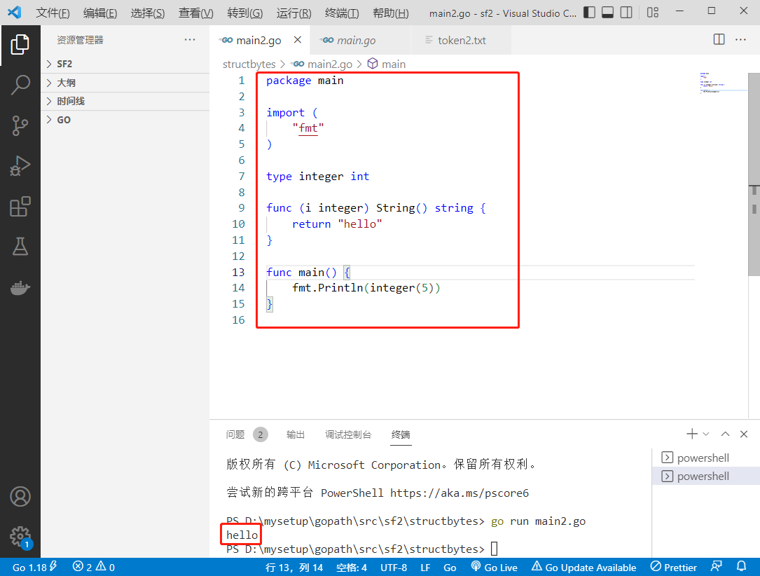
- 2022-07-26: what is the output of the following go language code? A:5; B:hello; C: Compilation error; D: Running error. package main import ( “fmt“ ) type integer in
- Nacos startup and login
- Final review of management information system
猜你喜欢

ceph操作

华为入局商用市场:趋势使然,挑战颇多
![[C language] recursively explain the tower of Hanoi problem](/img/a6/bbf1f19fc2a663df155cca53f2538a.png)
[C language] recursively explain the tower of Hanoi problem

Easy to use shell shortcuts
2022-07-26: what is the output of the following go language code? A:5; B:hello; C: Compilation error; D: Running error. package main import ( “fmt“ ) type integer in

Nacos startup and login

项目参数做成可配置项,@ConfigurationProperties注解的使用

Do you know about wechat merchant billing?

JS three methods of traversing arrays: map, foreach, filter
Full revolutionary networks for semantic segmentation (FCN)

随机推荐
Shell中的文本处理工具、cut [选项参数] filename 说明:默认分隔符是制表符、awk [选项参数] ‘/pattern1/{action1}filename 、awk 的内置变量
【软件工程期末复习】知识点+大题详解(E-R图、数据流图、N-S盒图、状态图、活动图、用例图....)
Install and configure Debian on a wired network
Interview must ask | what stages does a thread go through from creation to extinction?
The project parameters are made into configurable items, and the @configurationproperties annotation is used
Ribbon load balancing strategy and configuration, lazy loading and hungry loading of ribbon
好用移动APP自动化测试框架哪里找?收藏这份清单就好了!
RN开发系列<9>--Mobx(1)入门篇
playwright网络爬虫实战案例分享
数据分析师岗位分析
【C语言】递归详解汉诺塔问题
C get UUID
Convolution neural network -- convolution of gray image
深度学习领域图像分割FCN(Fully Convolutional Networks for Semantic Segmentation)
iPhone13再降价,其实只是做做样子,消费者都在等iPhone14
项目参数做成可配置项,@ConfigurationProperties注解的使用
Ref Hook
Standard C language 11
BSN IPFs (interstellar file system) private network introduction, functions, architecture and characteristics, access instructions
Redis interview question (2022)