当前位置:网站首页>Pandora IOT development board learning (RT thread) - Experiment 4 buzzer + motor experiment [key external interrupt] (learning notes)
Pandora IOT development board learning (RT thread) - Experiment 4 buzzer + motor experiment [key external interrupt] (learning notes)
2022-07-05 00:47:00 【Xiaohui_ Super】
This article code reference RT-Thread official BSP
List of articles
Experimental function
Routine source code :(main.c)
Functions realized by this experiment :4 Keys correspond to different functions ( Control the motor to turn left or right , Control buzzer off ), among 3 Keys are detected by external interruption ( Another key is detected by polling ), Most of the operation code is interrupting service ( Callback ) Function , The code of motor control and buzzer control is very simple , Is full of GPIO Write operations , It is not analyzed separately .
/* * Copyright (c) 2006-2018, RT-Thread Development Team * * SPDX-License-Identifier: Apache-2.0 * * Change Logs: * Date Author Notes * 2018-08-23 balanceTWK first implementation */

#include <rtthread.h>
#include <rtdevice.h>
#include <board.h>

#define DBG_TAG "main"
#define DBG_LVL DBG_LOG
#include <rtdbg.h>

enum
{

    MOTOR_STOP,
    MOTOR_LEFT,
    MOTOR_RIGHT
};

/*  Motor control  */
void motor_ctrl(rt_uint8_t turn)
{

    if (turn == MOTOR_STOP)
    {

        rt_pin_write(PIN_MOTOR_A, PIN_LOW);
        rt_pin_write(PIN_MOTOR_B, PIN_LOW);
    }
    else if (turn == MOTOR_LEFT)
    {

        rt_pin_write(PIN_MOTOR_A, PIN_LOW);
        rt_pin_write(PIN_MOTOR_B, PIN_HIGH);
    }
    else if (turn == MOTOR_RIGHT)
    {

        rt_pin_write(PIN_MOTOR_A, PIN_HIGH);
        rt_pin_write(PIN_MOTOR_B, PIN_LOW);
    }
    else
    {

        LOG_D("err parameter ! Please enter 0-2.");
    }
}

void beep_ctrl(rt_uint8_t on)
{

    if (on)
    {

        rt_pin_write(PIN_BEEP, PIN_HIGH);
    }
    else
    {

        rt_pin_write(PIN_BEEP, PIN_LOW);
    }
}

/*  Interrupt callback  */
void irq_callback(void *args)
{

    rt_uint32_t sign = (rt_uint32_t)args;
    switch (sign)
    {

    case PIN_KEY0:
        motor_ctrl(MOTOR_LEFT);
        LOG_D("KEY0 interrupt. motor turn left.");
        break;
    case PIN_KEY1:
        motor_ctrl(MOTOR_RIGHT);
        LOG_D("KEY1 interrupt. motor turn right.");
        break;
    case PIN_KEY2:
        motor_ctrl(MOTOR_STOP);
        LOG_D("KEY2 interrupt. motor stop.");
        break;
    default:
        LOG_E("error sign= %d !", sign);
        break;
    }
}

int main(void)
{

    unsigned int count = 1;

    /*  Set the key pin to the input mode  */
    rt_pin_mode(PIN_KEY0, PIN_MODE_INPUT_PULLUP);
    rt_pin_mode(PIN_KEY1, PIN_MODE_INPUT_PULLUP);
    rt_pin_mode(PIN_KEY2, PIN_MODE_INPUT_PULLUP);
    rt_pin_mode(PIN_WK_UP, PIN_MODE_INPUT_PULLDOWN);

    /*  Set the motor control pin to the input mode  */
    rt_pin_mode(PIN_MOTOR_A, PIN_MODE_OUTPUT);
    rt_pin_mode(PIN_MOTOR_B, PIN_MODE_OUTPUT);

    /*  Set buzzer pin to output mode  */
    rt_pin_mode(PIN_BEEP, PIN_MODE_OUTPUT);

    /*  Set the key interrupt mode and interrupt callback function  */
    rt_pin_attach_irq(PIN_KEY0, PIN_IRQ_MODE_FALLING, irq_callback, (void *)PIN_KEY0);
    rt_pin_attach_irq(PIN_KEY1, PIN_IRQ_MODE_FALLING, irq_callback, (void *)PIN_KEY1);
    rt_pin_attach_irq(PIN_KEY2, PIN_IRQ_MODE_FALLING, irq_callback, (void *)PIN_KEY2);

    /*  To interrupt  */
    rt_pin_irq_enable(PIN_KEY0, PIN_IRQ_ENABLE);
    rt_pin_irq_enable(PIN_KEY1, PIN_IRQ_ENABLE);
    rt_pin_irq_enable(PIN_KEY2, PIN_IRQ_ENABLE);

    while (count > 0)
    {

        if (rt_pin_read(PIN_WK_UP) == PIN_HIGH)
        {

            rt_thread_mdelay(50);
            if (rt_pin_read(PIN_WK_UP) == PIN_HIGH)
            {

                LOG_D("WK_UP pressed. beep on.");
                beep_ctrl(1);
            }
        }
        else
        {

            beep_ctrl(0);
        }
        rt_thread_mdelay(10);
        count++;
    }
    return 0;
}
Code analysis
rt_pin_mode()
The function is to GPIO Pin The initialization , Defined as
/* RT-Thread Hardware PIN APIs */
void rt_pin_mode(rt_base_t pin, rt_base_t mode)
{

    RT_ASSERT(_hw_pin.ops != RT_NULL);
    _hw_pin.ops->pin_mode(&_hw_pin.parent, pin, mode);
}
Parameters pin It's a rt_base_t Variable (long), Below GET_PIN() yes STM32 Of pin Value macro definition , Fill in capital letters for the first parameter , The second parameter is filled with numbers .
#define GET_PIN(PORTx,PIN) (rt_base_t)((16 * ( ((rt_base_t)__STM32_PORT(PORTx) - (rt_base_t)GPIOA)/(0x0400UL) )) + PIN)

#define __STM32_PORT(port) GPIO##port // ##  Is a character connector , If  port  by  A, said  GPIOA
For example, in the experiment
#define PIN_LED_R GET_PIN(E, 7), Express GPIOE GPIO_Pin7
at present RT-Thread Supported pin operating modes include :
#define PIN_MODE_OUTPUT 0x00 /*  Output  */
#define PIN_MODE_INPUT 0x01 /*  Input  */
#define PIN_MODE_INPUT_PULLUP 0x02 /*  Pull up input  */
#define PIN_MODE_INPUT_PULLDOWN 0x03 /*  Drop down input  */
#define PIN_MODE_OUTPUT_OD 0x04 /*  Open drain output  */
stay bsp Of drv_gpio.c In file , There is a bottom layer GPIO drive , Here is STM32 Of GPIO Driver function of mode setting ( You should be familiar with , Just use HAL Library written GPIO Initialization code )
static void stm32_pin_mode(rt_device_t dev, rt_base_t pin, rt_base_t mode)
{

    const struct pin_index *index;
    GPIO_InitTypeDef GPIO_InitStruct;

    index = get_pin(pin);
    if (index == RT_NULL)
    {

        return;
    }

    /* Configure GPIO_InitStructure */
    GPIO_InitStruct.Pin = index->pin;
    GPIO_InitStruct.Mode = GPIO_MODE_OUTPUT_PP;
    GPIO_InitStruct.Pull = GPIO_NOPULL;
    GPIO_InitStruct.Speed = GPIO_SPEED_FREQ_HIGH;

    if (mode == PIN_MODE_OUTPUT)
    {

        /* output setting */
        GPIO_InitStruct.Mode = GPIO_MODE_OUTPUT_PP;
        GPIO_InitStruct.Pull = GPIO_NOPULL;
    }
    else if (mode == PIN_MODE_INPUT)
    {

        /* input setting: not pull. */
        GPIO_InitStruct.Mode = GPIO_MODE_INPUT;
        GPIO_InitStruct.Pull = GPIO_NOPULL;
    }
    else if (mode == PIN_MODE_INPUT_PULLUP)
    {

        /* input setting: pull up. */
        GPIO_InitStruct.Mode = GPIO_MODE_INPUT;
        GPIO_InitStruct.Pull = GPIO_PULLUP;
    }
    else if (mode == PIN_MODE_INPUT_PULLDOWN)
    {

        /* input setting: pull down. */
        GPIO_InitStruct.Mode = GPIO_MODE_INPUT;
        GPIO_InitStruct.Pull = GPIO_PULLDOWN;
    }
    else if (mode == PIN_MODE_OUTPUT_OD)
    {

        /* output setting: od. */
        GPIO_InitStruct.Mode = GPIO_MODE_OUTPUT_OD;
        GPIO_InitStruct.Pull = GPIO_NOPULL;
    }

    HAL_GPIO_Init(index->gpio, &GPIO_InitStruct);
}
rt_pin_attach_irq()
This is a RT-Thread Break binding ( register ) function , It will call the corresponding functions in the current platform driver .
rt_err_t rt_pin_attach_irq(rt_int32_t pin, rt_uint32_t mode,
                             void (*hdr)(void *args), void  *args)
{

    RT_ASSERT(_hw_pin.ops != RT_NULL);
    if(_hw_pin.ops->pin_attach_irq)
    {

        return _hw_pin.ops->pin_attach_irq(&_hw_pin.parent, pin, mode, hdr, args);
    }
    return RT_ENOSYS;
}
bsp drive (drv_gpio.c) It defines STM32 Interrupt registration function of stm32_pin_attach_irq():
static rt_err_t stm32_pin_attach_irq(struct rt_device *device, rt_int32_t pin,
                                     rt_uint32_t mode, void (*hdr)(void *args), void *args)
{

    const struct pin_index *index;
    rt_base_t level;
    rt_int32_t irqindex = -1;

    index = get_pin(pin);
    if (index == RT_NULL)
    {

        return RT_ENOSYS;
    }
    irqindex = bit2bitno(index->pin);
    if (irqindex < 0 || irqindex >= ITEM_NUM(pin_irq_map))
    {

        return RT_ENOSYS;
    }

    level = rt_hw_interrupt_disable();
    if (pin_irq_hdr_tab[irqindex].pin == pin &&
            pin_irq_hdr_tab[irqindex].hdr == hdr &&
            pin_irq_hdr_tab[irqindex].mode == mode &&
            pin_irq_hdr_tab[irqindex].args == args)
    {

        rt_hw_interrupt_enable(level);
        return RT_EOK;
    }
    if (pin_irq_hdr_tab[irqindex].pin != -1)
    {

        rt_hw_interrupt_enable(level);
        return RT_EBUSY;
    }
    pin_irq_hdr_tab[irqindex].pin = pin;
    pin_irq_hdr_tab[irqindex].hdr = hdr;
    pin_irq_hdr_tab[irqindex].mode = mode;
    pin_irq_hdr_tab[irqindex].args = args;
    rt_hw_interrupt_enable(level);

    return RT_EOK;
}
attach The principle of function is very simple , It is to store the current interrupt information in an interrupt table in the driver code , The structure of the interrupt table is defined as :
struct rt_pin_irq_hdr
{

    rt_int16_t        pin;
    rt_uint16_t       mode;
    void (*hdr)(void *args);  //  Interrupt callback function
    void             *args;
};
rt_pin_irq_enable()
This is a RT-Thread Kernel pin Interrupt enable function , The actual operation is the platform driven corresponding function ,
rt_err_t rt_pin_irq_enable(rt_base_t pin, rt_uint32_t enabled)
{

    RT_ASSERT(_hw_pin.ops != RT_NULL);
    if(_hw_pin.ops->pin_irq_enable)
    {

        return _hw_pin.ops->pin_irq_enable(&_hw_pin.parent, pin, enabled);
    }
    return RT_ENOSYS;
}
STM32 The interrupt enabling function in the platform driver is as follows , The amount of code is still very large (HAL Configuration of external interrupts in the Library , Due to the consideration of different parameter options , So it's a lot of code ):
static rt_err_t stm32_pin_irq_enable(struct rt_device *device, rt_base_t pin,
                                     rt_uint32_t enabled)
{

    const struct pin_index *index;
    const struct pin_irq_map *irqmap;
    rt_base_t level;
    rt_int32_t irqindex = -1;
    GPIO_InitTypeDef GPIO_InitStruct;

    index = get_pin(pin);
    if (index == RT_NULL)
    {

        return RT_ENOSYS;
    }

    if (enabled == PIN_IRQ_ENABLE)
    {

        irqindex = bit2bitno(index->pin);
        if (irqindex < 0 || irqindex >= ITEM_NUM(pin_irq_map))
        {

            return RT_ENOSYS;
        }

        level = rt_hw_interrupt_disable();

        if (pin_irq_hdr_tab[irqindex].pin == -1)
        {

            rt_hw_interrupt_enable(level);
            return RT_ENOSYS;
        }

        irqmap = &pin_irq_map[irqindex];

        /* Configure GPIO_InitStructure */
        GPIO_InitStruct.Pin = index->pin;
        GPIO_InitStruct.Speed = GPIO_SPEED_FREQ_HIGH;
        switch (pin_irq_hdr_tab[irqindex].mode)
        {

        case PIN_IRQ_MODE_RISING:
            GPIO_InitStruct.Pull = GPIO_PULLDOWN;
            GPIO_InitStruct.Mode = GPIO_MODE_IT_RISING;
            break;
        case PIN_IRQ_MODE_FALLING:
            GPIO_InitStruct.Pull = GPIO_PULLUP;
            GPIO_InitStruct.Mode = GPIO_MODE_IT_FALLING;
            break;
        case PIN_IRQ_MODE_RISING_FALLING:
            GPIO_InitStruct.Pull = GPIO_NOPULL;
            GPIO_InitStruct.Mode = GPIO_MODE_IT_RISING_FALLING;
            break;
        }
        HAL_GPIO_Init(index->gpio, &GPIO_InitStruct);

        HAL_NVIC_SetPriority(irqmap->irqno, 5, 0);
        HAL_NVIC_EnableIRQ(irqmap->irqno);
        pin_irq_enable_mask |= irqmap->pinbit;

        rt_hw_interrupt_enable(level);
    }
    else if (enabled == PIN_IRQ_DISABLE)
    {

        irqmap = get_pin_irq_map(index->pin);
        if (irqmap == RT_NULL)
        {

            return RT_ENOSYS;
        }

        level = rt_hw_interrupt_disable();

        HAL_GPIO_DeInit(index->gpio, index->pin);

        pin_irq_enable_mask &= ~irqmap->pinbit;
#if defined(SOC_SERIES_STM32F0) || defined(SOC_SERIES_STM32G0)
        if (( irqmap->pinbit>=GPIO_PIN_0 )&&( irqmap->pinbit<=GPIO_PIN_1 ))
        {

            if(!(pin_irq_enable_mask&(GPIO_PIN_0|GPIO_PIN_1)))
            {

                HAL_NVIC_DisableIRQ(irqmap->irqno);
            }
        }
        else if (( irqmap->pinbit>=GPIO_PIN_2 )&&( irqmap->pinbit<=GPIO_PIN_3 ))
        {

            if(!(pin_irq_enable_mask&(GPIO_PIN_2|GPIO_PIN_3)))
            {

                HAL_NVIC_DisableIRQ(irqmap->irqno);
            }
        }
        else if (( irqmap->pinbit>=GPIO_PIN_4 )&&( irqmap->pinbit<=GPIO_PIN_15 ))
        {

            if(!(pin_irq_enable_mask&(GPIO_PIN_4|GPIO_PIN_5|GPIO_PIN_6|GPIO_PIN_7|GPIO_PIN_8|GPIO_PIN_9|
                                      GPIO_PIN_10|GPIO_PIN_11|GPIO_PIN_12|GPIO_PIN_13|GPIO_PIN_14|GPIO_PIN_15)))
            {

                HAL_NVIC_DisableIRQ(irqmap->irqno);
            }
        }
        else
        {

            HAL_NVIC_DisableIRQ(irqmap->irqno);
        }
#else
        if (( irqmap->pinbit>=GPIO_PIN_5 )&&( irqmap->pinbit<=GPIO_PIN_9 ))
        {

            if(!(pin_irq_enable_mask&(GPIO_PIN_5|GPIO_PIN_6|GPIO_PIN_7|GPIO_PIN_8|GPIO_PIN_9)))
            {

                HAL_NVIC_DisableIRQ(irqmap->irqno);
            }
        }
        else if (( irqmap->pinbit>=GPIO_PIN_10 )&&( irqmap->pinbit<=GPIO_PIN_15 ))
        {

            if(!(pin_irq_enable_mask&(GPIO_PIN_10|GPIO_PIN_11|GPIO_PIN_12|GPIO_PIN_13|GPIO_PIN_14|GPIO_PIN_15)))
            {

                HAL_NVIC_DisableIRQ(irqmap->irqno);
            }
        }
        else
        {

            HAL_NVIC_DisableIRQ(irqmap->irqno);
        }
#endif
        rt_hw_interrupt_enable(level);
    }
    else
    {

        return -RT_ENOSYS;
    }

    return RT_EOK;
}
Interrupt handling function
The interrupt handler is already in main.c In the definition of , It's not shown here .
When an external interrupt is triggered , Will trigger HAL Library interrupt function HAL_GPIO_EXTI_Callback(), and STM32 bsp In this function pin_irq_hdr(bit2bitno(GPIO_Pin));, This function will call the corresponding callback function according to the interrupt number assigned during interrupt registration .
HAL_GPIO_EXTI_Callback()
#if defined(SOC_SERIES_STM32G0)
void HAL_GPIO_EXTI_Rising_Callback(uint16_t GPIO_Pin)
{

    pin_irq_hdr(bit2bitno(GPIO_Pin));
}

void HAL_GPIO_EXTI_Falling_Callback(uint16_t GPIO_Pin)
{

    pin_irq_hdr(bit2bitno(GPIO_Pin));
}
#else
void HAL_GPIO_EXTI_Callback(uint16_t GPIO_Pin)
{

    pin_irq_hdr(bit2bitno(GPIO_Pin));
}
#endif
pin_irq_hdr()
rt_inline void pin_irq_hdr(int irqno)
{

    if (pin_irq_hdr_tab[irqno].hdr)
    {

        pin_irq_hdr_tab[irqno].hdr(pin_irq_hdr_tab[irqno].args);
    }
}
rt_pin_read()
GPIO Read function , Here is the definition of the function :
int  rt_pin_read(rt_base_t pin)
{

    RT_ASSERT(_hw_pin.ops != RT_NULL);
    return _hw_pin.ops->pin_read(&_hw_pin.parent, pin);
}
and GPIO The mode configuration function is similar , It will call the corresponding function in the underlying driver , The underlying function is through HAL_GPIO_ReadPin() To get GPIO The level of .
static int stm32_pin_read(rt_device_t dev, rt_base_t pin)
{

    int value;
    const struct pin_index *index;

    value = PIN_LOW;

    index = get_pin(pin);
    if (index == RT_NULL)
    {

        return value;
    }

    value = HAL_GPIO_ReadPin(index->gpio, index->pin);

    return value;
}
rt_thread_mdelay()
This is a RT-Thread Millisecond delay function , The definition is as follows :
rt_err_t rt_thread_mdelay(rt_int32_t ms)
{

    rt_tick_t tick;

	//  Get the required clock beat
    tick = rt_tick_from_millisecond(ms);

	//  Block the corresponding beat time
    return rt_thread_sleep(tick);
}
rt_tick_from_millisecond()
/** *  Work out  ms  The number of corresponding clock beats  * * * @param ms the specified millisecond * - Negative Number wait forever * - Zero not wait * - Max 0x7fffffff * * @return the calculated tick */
rt_tick_t rt_tick_from_millisecond(rt_int32_t ms)
{

    rt_tick_t tick;

    if (ms < 0)
    {

        tick = (rt_tick_t)RT_WAITING_FOREVER;  // -1
    }
    else
    {

    	//  take “ Beats per second ” / 1000 * ms, Calculate the corresponding second beats
        tick = RT_TICK_PER_SECOND * (ms / 1000);

		//  Plus less than  1000ms  Part of the beat number
        tick += (RT_TICK_PER_SECOND * (ms % 1000) + 999) / 1000;
    }

    /* return the calculated tick */
    return tick;
}
rt_thread_sleep()
Thread sleep ( Hang up ) function , The parameter is the number of system beats :
/** *  This function can make the current thread hang for a period of time ( from  tick  decision ) * * @param tick the sleep ticks * * @return RT_EOK */
rt_err_t rt_thread_sleep(rt_tick_t tick)
{

    register rt_base_t temp;
    struct rt_thread *thread;

    /* set to current thread */
    thread = rt_thread_self();
    RT_ASSERT(thread != RT_NULL);
    RT_ASSERT(rt_object_get_type((rt_object_t)thread) == RT_Object_Class_Thread);

    /* disable interrupt */
    temp = rt_hw_interrupt_disable();

    /* suspend thread */
    rt_thread_suspend(thread);

    /* reset the timeout of thread timer and start it */
    rt_timer_control(&(thread->thread_timer), RT_TIMER_CTRL_SET_TIME, &tick);
    rt_timer_start(&(thread->thread_timer));

    /* enable interrupt */
    rt_hw_interrupt_enable(temp);

    rt_schedule();

    /* clear error number of this thread to RT_EOK */
    if (thread->error == -RT_ETIMEOUT)
        thread->error = RT_EOK;

    return RT_EOK;
}
LOG_D()
In this study , We can LOG_D() As rt_kprintf(),
#define dbg_log_line(lvl, color_n, fmt, ...) \ do \ {
       \ _DBG_LOG_HDR(lvl, color_n); \ rt_kprintf(fmt, ##__VA_ARGS__); \ _DBG_LOG_X_END; \ } \ while (0)
LOG_D yes RT-Thread A log printing function in the kernel , Details visible :《RT-Thread Document center ——ulog journal 》
RT-Thread Log API Include :
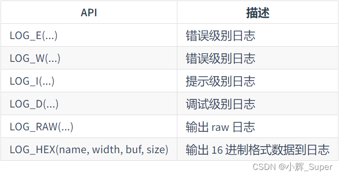
rt_pin_write()
GPIO Write function , Here is the definition of the function ,
void rt_pin_write(rt_base_t pin, rt_base_t value)
{

    RT_ASSERT(_hw_pin.ops != RT_NULL);
    _hw_pin.ops->pin_write(&_hw_pin.parent, pin, value);
}
and GPIO The mode configuration function is similar , It will call the corresponding function in the underlying driver , The underlying function is through HAL_GPIO_WritePin() To complete GPIO Pin Modification of .
static void stm32_pin_write(rt_device_t dev, rt_base_t pin, rt_base_t value)
{

    const struct pin_index *index;

    index = get_pin(pin);
    if (index == RT_NULL)
    {

        return;
    }

    HAL_GPIO_WritePin(index->gpio, index->pin, (GPIO_PinState)value);
}
边栏推荐
- The waterfall flow layout demo2 (method 2) used by the uniapp wechat applet (copy and paste can be used without other processing)
- What if the programmer's SQL data script coding ability is weak and Bi can't do it?
- URLs and URIs
- Ap8022 switching power supply small household appliances ACDC chip offline switching power supply IC
- IT转测试岗,从迷茫到坚定我究竟付出了什么?
- Acwing164. Accessibility Statistics (topological sorting +bitset)
- Some basic functions of enterprise projects are developed, and important things are saved to online first a
- Detailed explanation of openharmony resource management
- P4281 [ahoi2008] emergency assembly / gathering (LCA)
- Innovation leads the direction. Huawei Smart Life launches new products in the whole scene
猜你喜欢
Get to know ROS for the first time
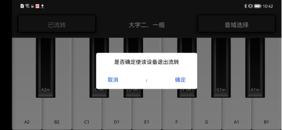
Summer challenge brings you to play harmoniyos multi terminal piano performance
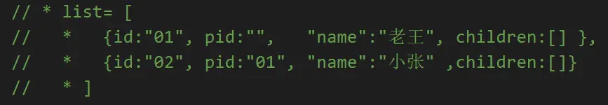
js如何实现数组转树
Deux nombres se remplacent
Huawei employs millions of data governance experts! The 100 billion market behind it deserves attention
1189. Maximum number of "balloons"

abc 258 G - Triangle(bitset)
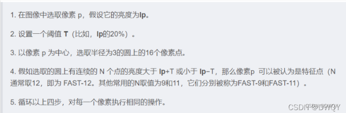
ORB(Oriented FAST and Rotated BRIEF)
![P3304 [sdoi2013] diameter (diameter of tree)](/img/5c/984675bf4517481f80f54657c6c7ad.png)
P3304 [sdoi2013] diameter (diameter of tree)
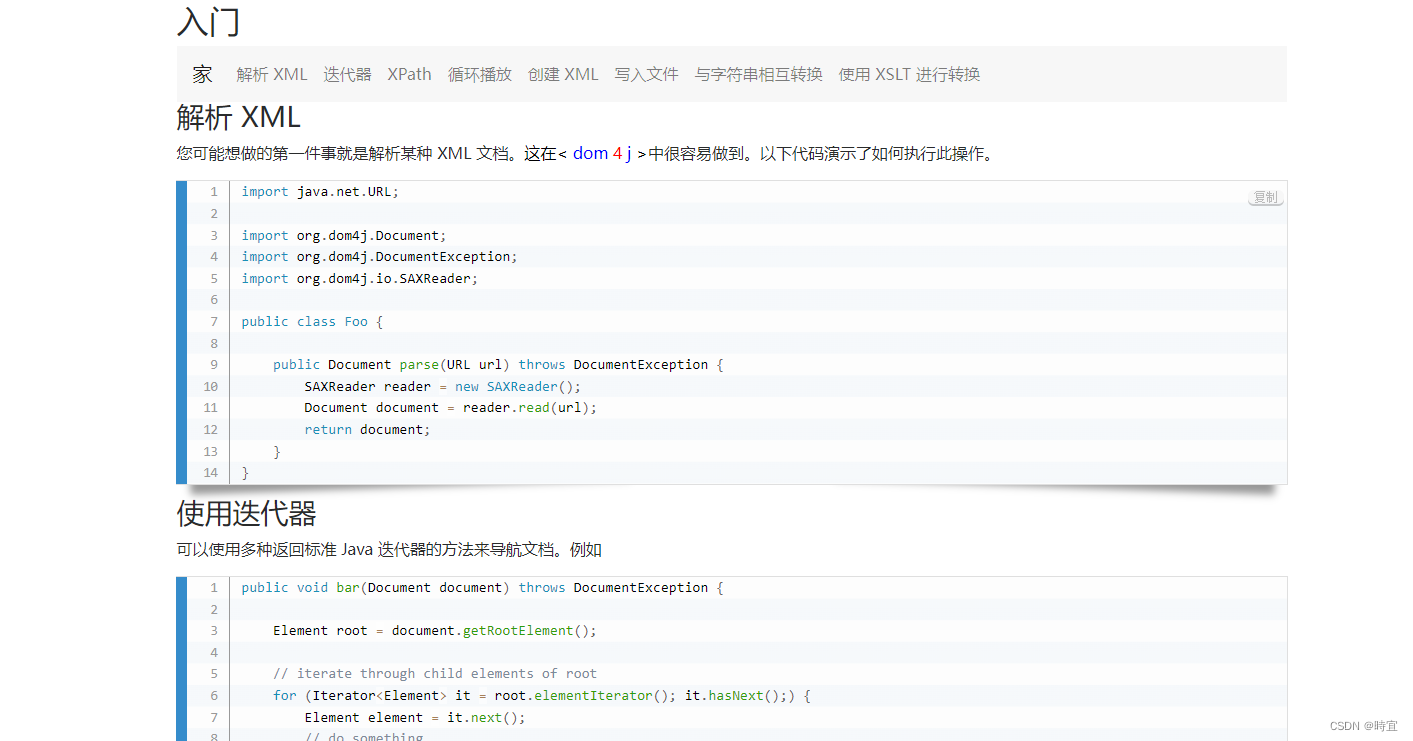
Parsing of XML
随机推荐
有哪些收益稳定的理财产品,这两个都不错
||Interview questions you will encounter
GDB common commands
Hologres Query管理及超时处理
Consolidated expression C case simple variable operation
Nine Qi single chip microcomputer ny8b062d single key control four LED States
There is a new Post-00 exam king in the testing department. I really can't do it in my old age. I have
js如何实现数组转树
SAP UI5 应用开发教程之一百零七 - SAP UI5 OverflowToolbar 容器控件介绍的试读版
Reasons and solutions of redis cache penetration and avalanche
挖财学院开户安全的吗?开户怎么开?
Acwing164. Accessibility Statistics (topological sorting +bitset)
P4408 [NOI2003] 逃学的小孩(树的直径)
实战模拟│JWT 登录认证
Date time type and format in MySQL
Mongodb series learning notes tutorial summary
Innovation leads the direction. Huawei Smart Life launches new products in the whole scene
全网最全正则实战指南,拿走不谢
NPM install error forced installation
Getting started with Paxos