当前位置:网站首页>Pandora IOT development board learning (HAL Library) - Experiment 12 RTC real-time clock experiment (learning notes)
Pandora IOT development board learning (HAL Library) - Experiment 12 RTC real-time clock experiment (learning notes)
2022-07-07 14:38:00 【Xiaohui_ Super】
This code refers to the punctual atomic routine
List of articles
Experimental function
LCD and USARMT The code is not analyzed
Routine source code :(main.c)
The functions realized in this experiment : Set up RTC Time ( RTC In the initialization function ),RTC Cycle wakeup interrupt LED_B The twinkle of ,RTC The alarm clock makes the buzzer go off ( main() The alarm time is not set in the function , So this function should not be fully realized ).LCD Every time 10ms Refresh the display of time and date (LCD The code is not analyzed in this article ).
#include "sys.h"
#include "usart.h"
#include "delay.h"
#include "led.h"
#include "beep.h"
#include "lcd.h"
#include "usmart.h"
#include "rtc.h"

/********************************************************************************* ___ _ _____ _____ _ _ _____ _____ _ __ / _ \ | | |_ _|| ___|| \ | ||_ _|| ___|| | / / / /_\ \| | | | | |__ | \| | | | | |__ | |/ / | _ || | | | | __| | . ` | | | | __| | \ | | | || |_____| |_ | |___ | |\ | | | | |___ | |\ \ \_| |_/\_____/\___/ \____/ \_| \_/ \_/ \____/ \_| \_/ * ****************************************************************************** *  The punctual atoms  Pandora STM32L475 IoT Development board   experiment 12 * RTC Real time clock experiment  HAL Library version  *  Technical support :www.openedv.com *  Taobao shop :http://openedv.taobao.com *  Focus on wechat public platform wechat :" The punctual atoms ", Free access STM32 Information . *  Guangzhou Xingyi Electronic Technology Co., Ltd  *  author : The punctual atoms  @ALIENTEK * ******************************************************************************/

int main(void)
{

    u8 t = 0;
	u8 cnt = 0;
    char tbuf[40];

    RTC_TimeTypeDef RTC_TimeStruct;
    RTC_DateTypeDef RTC_DateStruct;

    HAL_Init();
    SystemClock_Config();		// Initialize the system clock to 80M
    delay_init(80); 			// Initialization delay function  80M The system clock
    uart_init(115200);			// Initialize serial port , The baud rate is 115200
    usmart_dev.init(80);		// initialization USMART 80M The system clock

    LED_Init();					// initialization LED
    BEEP_Init();				// initialization BEEP
    LCD_Init();					// initialization LCD

    RTC_Init();					// initialization RTC
    RTC_Set_WakeUp(RTC_WAKEUPCLOCK_CK_SPRE_16BITS, 0); // To configure WAKE UP interrupt ,1 Interrupt once per second

	POINT_COLOR = RED;
    Display_ALIENTEK_LOGO(0, 0);
    LCD_ShowString(30, 95, 200, 16, 16, "Pandora STM32L4 IOT");
    LCD_ShowString(30, 115, 200, 16, 16, "RTC TEST");
    LCD_ShowString(30, 135, 200, 16, 16, "[email protected]");
    LCD_ShowString(30, 155, 200, 16, 16, "2018/10/27");
	POINT_COLOR = BLUE;

    while(1)
    {

        t++;

        if((t % 10) == 0)			// Every time 100ms Update the display data once
        {

            HAL_RTC_GetTime(&RTC_Handler, &RTC_TimeStruct, RTC_FORMAT_BIN);
            sprintf((char*)tbuf, "Time:%02d:%02d:%02d", RTC_TimeStruct.Hours, RTC_TimeStruct.Minutes, RTC_TimeStruct.Seconds);
            LCD_ShowString(30, 175, 210, 16, 16, tbuf);
            HAL_RTC_GetDate(&RTC_Handler, &RTC_DateStruct, RTC_FORMAT_BIN);
            sprintf((char*)tbuf, "Date:20%02d-%02d-%02d", RTC_DateStruct.Year, RTC_DateStruct.Month, RTC_DateStruct.Date);
            LCD_ShowString(30, 195, 210, 16, 16, tbuf);
            sprintf((char*)tbuf, "Week:%d", RTC_DateStruct.WeekDay);
            LCD_ShowString(30, 215, 210, 16, 16, tbuf);
        }

		if( BEEP_Read )				// Alarm time , Buzzer ring 1S Stop after
		{

			cnt++;
			if(cnt>=100)	{
    BEEP(0);cnt=0;}
		}

        if((t % 20) == 0)LED_R_TogglePin;	// Every time 200ms, Flip once LED_R

        delay_ms(10);
    }
}
Code analysis
HAL_Init()
HAL_Init() The definition is as follows :( See notes for specific functions )
HAL_StatusTypeDef HAL_Init(void)
{

  HAL_StatusTypeDef  status = HAL_OK;

  /*  To configure  Flash  Prefetch , Instruction cache , Data caching  */
  /*  Default configuration is : Pre access is closed   Instruction cache and data cache are enabled  */
#if (INSTRUCTION_CACHE_ENABLE == 0) // Flash Enable pre access configuration , Can accelerate CPU Execution of code
   __HAL_FLASH_INSTRUCTION_CACHE_DISABLE();
#endif /* INSTRUCTION_CACHE_ENABLE */

#if (DATA_CACHE_ENABLE == 0)
   __HAL_FLASH_DATA_CACHE_DISABLE();
#endif /* DATA_CACHE_ENABLE */

#if (PREFETCH_ENABLE != 0)
  __HAL_FLASH_PREFETCH_BUFFER_ENABLE();
#endif /* PREFETCH_ENABLE */

  /* Set Interrupt Group Priority */
  HAL_NVIC_SetPriorityGrouping(NVIC_PRIORITYGROUP_2); //  To configure  NVIC  Priority groups

  /* Use SysTick as time base source and configure 1ms tick (default clock after Reset is MSI) */
  if (HAL_InitTick(TICK_INT_PRIORITY) != HAL_OK) // Initialize tick timer , The clock beat is set to  1ms
  {

    status = HAL_ERROR;
  }
  else
  {

    /* Init the low level hardware */
    HAL_MspInit(); //  Low speed peripheral initialization , such as  GPIO、 Interrupt, etc ( Use  STM32CubeMx  Low speed peripherals are initialized when generating code
                   //  The code is in this kind of function , In other cases, this function can be ignored
  }

  /* Return function status */
  return status;
}
HAL_InitTick()
Tick timer clock beat initialization function
__weak HAL_StatusTypeDef HAL_InitTick(uint32_t TickPriority)
{

  HAL_StatusTypeDef  status = HAL_OK;

  /*Configure the SysTick to have interrupt in 1ms time basis*/
  if (HAL_SYSTICK_Config(SystemCoreClock/1000UL) != 0U) //  The system clock /1000, The interruption period is  1ms
  {

    status = HAL_ERROR;
  }
  else
  {

    /*Configure the SysTick IRQ priority */
    HAL_NVIC_SetPriority(SysTick_IRQn, TickPriority, 0); //  Set the interrupt priority of the tick timer to the highest
  }

  /* Return function status */
  return status;
}
SystemClock_Config()
SystemClock_Config() The function is defined as follows :( See notes for specific functions , For reference only )
void SystemClock_Config(void)
{

    HAL_StatusTypeDef	ret = HAL_OK;

    RCC_OscInitTypeDef RCC_OscInitStruct; //  Define oscillator initialization structure variables
    RCC_ClkInitTypeDef RCC_ClkInitStruct; //  Define clock initialization structure variables

    __HAL_RCC_PWR_CLK_ENABLE(); //  Enable power control clock

    /*Initializes the CPU, AHB and APB busses clocks*/
    RCC_OscInitStruct.OscillatorType = RCC_OSCILLATORTYPE_HSE; //  take  HSE( External high-speed clock ) As a clock source
    RCC_OscInitStruct.HSEState = RCC_HSE_ON;  //  Turn on  HSE
    RCC_OscInitStruct.PLL.PLLState = RCC_PLL_ON; //  Turn on  PLL( PLL )
    RCC_OscInitStruct.PLL.PLLSource = RCC_PLLSOURCE_HSE; //  take  HSE  As  PLL  The clock source of
    RCC_OscInitStruct.PLL.PLLM = 1; // PLL-VCO  Input clock frequency division coefficient ,1  Express  2  frequency division (8 / 2 = 4M, The external crystal oscillator frequency of the development board is  8MHz)
    RCC_OscInitStruct.PLL.PLLN = 20; // PLL-VCO  Output clock frequency multiplication coefficient ,4 * 20 = 80M, That is, the output clock frequency is  80MHz
    RCC_OscInitStruct.PLL.PLLP = RCC_PLLP_DIV7; // SAI  Frequency division coefficient of clock
    RCC_OscInitStruct.PLL.PLLQ = RCC_PLLQ_DIV2; // SDMMC1, RNG  and  USB  Clock frequency division coefficient
    RCC_OscInitStruct.PLL.PLLR = RCC_PLLR_DIV2; //  Frequency division coefficient of the main system clock

    ret = HAL_RCC_OscConfig(&RCC_OscInitStruct); // Initialize clock configuration

    if(ret != HAL_OK)	while(1);

    /*Initializes the CPU, AHB and APB busses clocks*/
    RCC_ClkInitStruct.ClockType = RCC_CLOCKTYPE_HCLK | RCC_CLOCKTYPE_SYSCLK
                                  | RCC_CLOCKTYPE_PCLK1 | RCC_CLOCKTYPE_PCLK2; //  Configure all clocks at the same time
    RCC_ClkInitStruct.SYSCLKSource = RCC_SYSCLKSOURCE_PLLCLK; //  take  PLL  As the clock source of the system
    RCC_ClkInitStruct.AHBCLKDivider = RCC_SYSCLK_DIV1; // AHB  Regardless of the frequency
    RCC_ClkInitStruct.APB1CLKDivider = RCC_HCLK_DIV1; // APB1  Regardless of the frequency
    RCC_ClkInitStruct.APB2CLKDivider = RCC_HCLK_DIV1; // APB2  Regardless of the frequency


    ret	= HAL_RCC_ClockConfig(&RCC_ClkInitStruct, FLASH_LATENCY_4); //  Configure the initial structure variable of the clock ,
    // Use  Flash  Delay 4, Wait state ( Delay ) The quantity of should be according to CPU The clock (HCLK) Frequency and internal voltage range , How to
    // Please refer to the chip manual

    if(ret != HAL_OK)	while(1);

    /*Configure the main internal regulator output voltage*/
    ret = HAL_PWREx_ControlVoltageScaling(PWR_REGULATOR_VOLTAGE_SCALE1); // Internal register output voltage configuration
    //  Here is  HAL_PWREx_ControlVoltageScaling()  Part of the function description :
    //PWR_REGULATOR_VOLTAGE_SCALE1 Regulator voltage output range 1 mode, typical output voltage
    // at 1.2 V, system frequency up to 80 MHz.

    if(ret != HAL_OK)	while(1);
}
delay_init()
The tick timer is already HAL_Init() Initialization in , The following function is actually for fac_us Given a value ( At present, the operating system is not involved , Other code will not be studied for the time being ).
static u32 fac_us = 0;							//us Delay multiplier
/** * @brief  Initialization delay function ,SYSTICK The clock is fixed to AHB The clock  * * @param SYSCLK  System clock frequency  * * @return void */
void delay_init(u8 SYSCLK)
{

#if SYSTEM_SUPPORT_OS // If support is needed OS.
    u32 reload;
#endif
    HAL_SYSTICK_CLKSourceConfig(SYSTICK_CLKSOURCE_HCLK);//SysTick The frequency is HCLK
    fac_us = SYSCLK;						// Whether used or not OS,fac_us You need to use

#if SYSTEM_SUPPORT_OS // If support is needed OS.
    reload = SYSCLK;					  // The number of counts per second   Unit is K
    reload *= 1000000 / delay_ostickspersec;	// according to delay_ostickspersec Set the overflow time
    //reload by 24 Bit register , Maximum :16777216, stay 80M Next , about 209.7ms about
    fac_ms = 1000 / delay_ostickspersec;		// representative OS The minimum unit that can delay
    SysTick->CTRL |= SysTick_CTRL_TICKINT_Msk; // Turn on SYSTICK interrupt
    SysTick->LOAD = reload; 					// Every time 1/OS_TICKS_PER_SEC Second break once
    SysTick->CTRL |= SysTick_CTRL_ENABLE_Msk; // Turn on SYSTICK
#else
#endif
}
LED_Init()
/** * @brief LED IO Initialization function  * * @param void * * @return void */
void LED_Init(void)
{

	/* LED-B PE9 LED-G PE8 LED-R PE7 */
    GPIO_InitTypeDef GPIO_InitStruct;

    __HAL_RCC_GPIOE_CLK_ENABLE();

    GPIO_InitStruct.Pin = GPIO_PIN_7 | GPIO_PIN_8 | GPIO_PIN_9;
    GPIO_InitStruct.Mode = GPIO_MODE_OUTPUT_PP;
    GPIO_InitStruct.Pull = GPIO_PULLUP;
    GPIO_InitStruct.Speed = GPIO_SPEED_FREQ_HIGH;
    HAL_GPIO_Init(GPIOE, &GPIO_InitStruct);

    HAL_GPIO_WritePin(GPIOE, GPIO_PIN_7 | GPIO_PIN_8 | GPIO_PIN_9, GPIO_PIN_SET);
}
BEEP_Init()
/** * @brief  Buzzer  IO Initialization function  * * @param void * * @return void */
void BEEP_Init(void)
{

    GPIO_InitTypeDef GPIO_InitStruct;  //  Define a GPIO Initializing structure variables

    __HAL_RCC_GPIOB_CLK_ENABLE(); //  Can make GPIOE The clock of

    //PB2
    GPIO_InitStruct.Pin = GPIO_PIN_2; //  Set the corresponding pin
    GPIO_InitStruct.Mode = GPIO_MODE_OUTPUT_PP;  //  Push pull output mode
    GPIO_InitStruct.Pull = GPIO_PULLDOWN;  //  Default dropdown
    GPIO_InitStruct.Speed = GPIO_SPEED_FREQ_HIGH;  //  The speed is set to high speed (25 MHz to 50 MHz)
    HAL_GPIO_Init(GPIOB, &GPIO_InitStruct);  //  Initializing structure variables

    HAL_GPIO_WritePin(GPIOB, GPIO_PIN_2, GPIO_PIN_RESET);  // take  IO  Pull it down
}
RTC_Init()
/** * @brief RTC initialization  * * @param void * * @return u8 0, Successful initialization ; * 2, Failed to enter initialization mode ; */
u8 RTC_Init(void)
{

    RTC_Handler.Instance = RTC;
    RTC_Handler.Init.HourFormat = RTC_HOURFORMAT_24; //RTC Set to 24 Hour format
    RTC_Handler.Init.AsynchPrediv = 0X7F;         //RTC Asynchronous frequency division coefficient (1~0X7F)
    RTC_Handler.Init.SynchPrediv = 0XFF;          //RTC Synchronous frequency division coefficient (0~7FFF)
    RTC_Handler.Init.OutPut = RTC_OUTPUT_DISABLE;
    RTC_Handler.Init.OutPutPolarity = RTC_OUTPUT_POLARITY_HIGH;
    RTC_Handler.Init.OutPutType = RTC_OUTPUT_TYPE_OPENDRAIN;

    if(HAL_RTC_Init(&RTC_Handler) != HAL_OK) return 2;

    if(HAL_RTCEx_BKUPRead(&RTC_Handler, RTC_BKP_DR0) != 0x32F2) // Is it configured for the first time
    {

        RTC_Set_Time(23, 59, 56, RTC_HOURFORMAT12_PM);	     // Setup time  , Modify... According to the actual time
        RTC_Set_Date(15, 12, 27, 7);		                 // Setting date
        HAL_RTCEx_BKUPWrite(&RTC_Handler, RTC_BKP_DR0, 0x32F2); // The tag has been initialized
    }

    return 0;
}
HAL_RTC_MspInit()
Underlying driver function , It mainly configures the power clock , Cancel backup and write protection , Crystal oscillator clock selection , Can make RTC The clock .
/** * @brief RTC Bottom drive , Clock configuration , This function will be HAL_RTC_Init() call  * * @param hrtc RTC Handle  * * @return void */
void HAL_RTC_MspInit(RTC_HandleTypeDef* hrtc)
{

    RCC_OscInitTypeDef RCC_OscInitStruct;
    RCC_PeriphCLKInitTypeDef PeriphClkInitStruct;

    __HAL_RCC_PWR_CLK_ENABLE();// Enable power clock PWR
    HAL_PWR_EnableBkUpAccess();// Remove write protection from backup area

    RCC_OscInitStruct.OscillatorType = RCC_OSCILLATORTYPE_LSE; //LSE To configure
    RCC_OscInitStruct.PLL.PLLState = RCC_PLL_NONE;
    RCC_OscInitStruct.LSEState = RCC_LSE_ON;                //RTC Use LSE
    HAL_RCC_OscConfig(&RCC_OscInitStruct);

    PeriphClkInitStruct.PeriphClockSelection = RCC_PERIPHCLK_RTC; // The peripheral is RTC
    PeriphClkInitStruct.RTCClockSelection = RCC_RTCCLKSOURCE_LSE; //RTC The clock source is LSE
    HAL_RCCEx_PeriphCLKConfig(&PeriphClkInitStruct);

    __HAL_RCC_RTC_ENABLE();//RTC Clock enable
}
HAL_RTCExBKURead()
The following is the prototype of this function , The effect is to RTC Backup register read data .
 /** * @brief Read data from the specified RTC Backup data Register. * @param hrtc RTC handle * @param BackupRegister RTC Backup data Register number. * This parameter can be: RTC_BKP_DRx where x can be from 0 to 31 to * specify the register. * @retval Read value */
uint32_t HAL_RTCEx_BKUPRead(RTC_HandleTypeDef *hrtc, uint32_t BackupRegister)
RTC_Set_Time()
/** * @brief RTC Time setting function  * * @param hour  Hours  * @param min  minute  * @param sec  Second  * @param ampm @RTC_AM_PM_Definitions:RTC_HOURFORMAT12_AM/RTC_HOURFORMAT12_PM * * @return HAL_StatusTypeDef SUCEE(1), success  * ERROR(0), Failed to enter initialization mode  */
HAL_StatusTypeDef RTC_Set_Time(u8 hour, u8 min, u8 sec, u8 ampm)
{

    RTC_TimeTypeDef RTC_TimeStructure;

    RTC_TimeStructure.Hours = hour;
    RTC_TimeStructure.Minutes = min;
    RTC_TimeStructure.Seconds = sec;
    RTC_TimeStructure.TimeFormat = ampm;
    RTC_TimeStructure.DayLightSaving = RTC_DAYLIGHTSAVING_NONE;
    RTC_TimeStructure.StoreOperation = RTC_STOREOPERATION_RESET;
    return HAL_RTC_SetTime(&RTC_Handler, &RTC_TimeStructure, RTC_FORMAT_BIN);
}
HAL_RTC_SetTime()
HAL Library RTC Time setting function prototype :
/** * @brief Set RTC current time. * @param hrtc RTC handle * @param sTime Pointer to Time structure * @param Format Specifies the format of the entered parameters. * This parameter can be one of the following values: * @arg RTC_FORMAT_BIN: Binary data format * @arg RTC_FORMAT_BCD: BCD data format * @retval HAL status */
HAL_StatusTypeDef HAL_RTC_SetTime(RTC_HandleTypeDef *hrtc, RTC_TimeTypeDef *sTime, uint32_t Format)
RTC_Set_Date()
/** * @brief RTC Date setting function  * * @param year  year  * @param month  month  * @param date  Japan  * @param week  week (1~7,0, illegal !) * * @return HAL_StatusTypeDef SUCEE(1), success  * ERROR(0), Failed to enter initialization mode  */
HAL_StatusTypeDef RTC_Set_Date(u8 year, u8 month, u8 date, u8 week)
{

    RTC_DateTypeDef RTC_DateStructure;

    RTC_DateStructure.Date = date;
    RTC_DateStructure.Month = month;
    RTC_DateStructure.WeekDay = week;
    RTC_DateStructure.Year = year;
    return HAL_RTC_SetDate(&RTC_Handler, &RTC_DateStructure, RTC_FORMAT_BIN);
}
HAL_RTC_SetDate()
HAL library RTC Date setting function prototype :
/** * @brief Set RTC current date. * @param hrtc RTC handle * @param sDate Pointer to date structure * @param Format specifies the format of the entered parameters. * This parameter can be one of the following values: * @arg RTC_FORMAT_BIN: Binary data format * @arg RTC_FORMAT_BCD: BCD data format * @retval HAL status */
HAL_StatusTypeDef HAL_RTC_SetDate(RTC_HandleTypeDef *hrtc, RTC_DateTypeDef *sDate, uint32_t Format)
HAL_RTCEx_BKUPWrite()
The following is the prototype of this function , The effect is to RTC Backup register writes data .
/** * @brief Write a data in a specified RTC Backup data register. * @param hrtc RTC handle * @param BackupRegister RTC Backup data Register number. * This parameter can be: RTC_BKP_DRx where x can be from 0 to 31 to * specify the register. * @param Data Data to be written in the specified Backup data register. * @retval None */
void HAL_RTCEx_BKUPWrite(RTC_HandleTypeDef *hrtc, uint32_t BackupRegister, uint32_t Data)
RTC_Set_WakeUp()
RTC Periodic wake-up setting , Should have been in HAL_RTC_MspInit() Set in , But now it is defined separately ,main() I chose RTC_WAKEUPCLOCK_CK_SPRE_16BITS To achieve 1s interrupt .
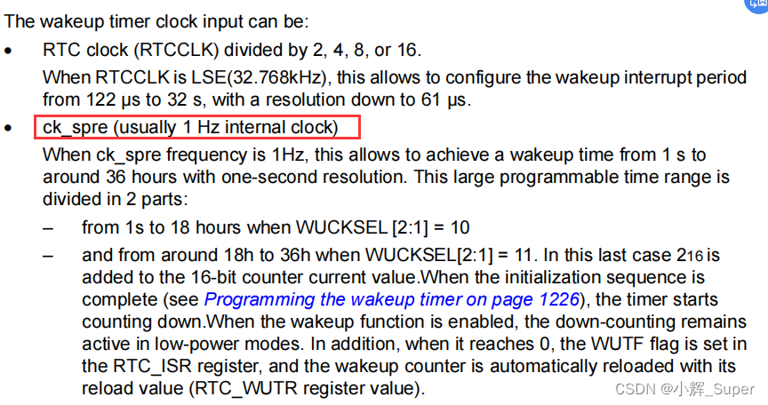
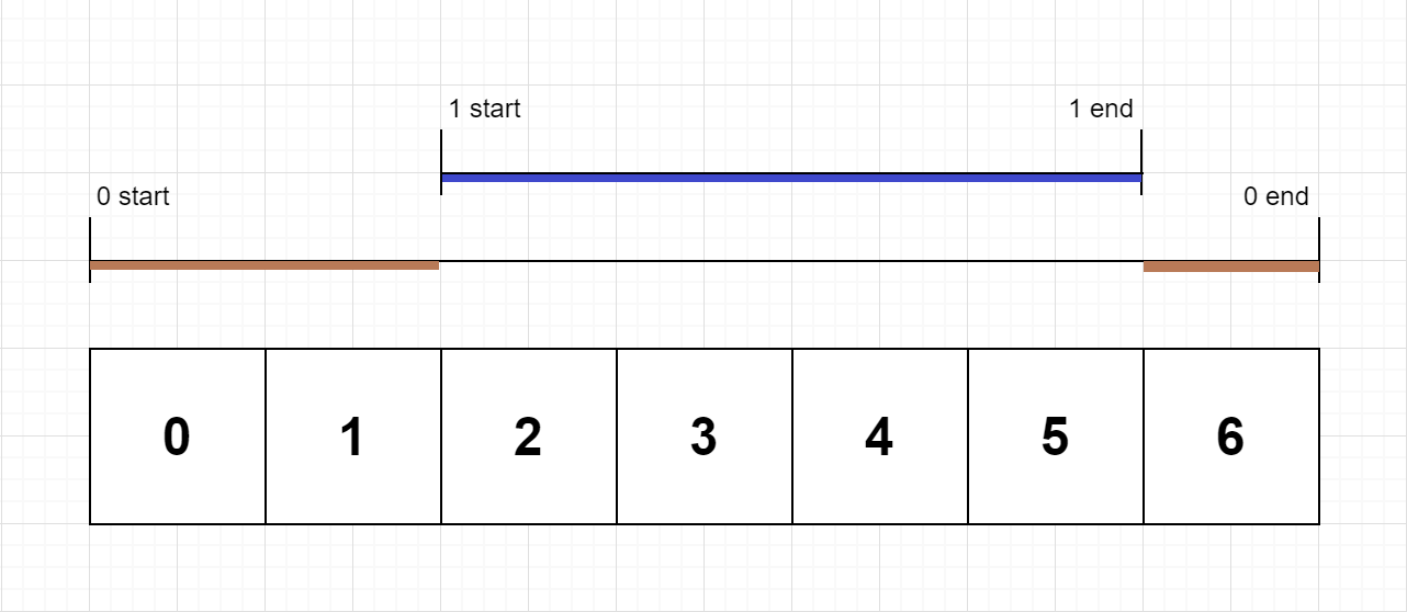
/** * @brief  Periodic wake-up timer settings  * * @param wksel @ref RTCEx_Wakeup_Timer_Definitions * #define RTC_WAKEUPCLOCK_RTCCLK_DIV16 ((uint32_t)0x00000000) * #define RTC_WAKEUPCLOCK_RTCCLK_DIV8 ((uint32_t)0x00000001) * #define RTC_WAKEUPCLOCK_RTCCLK_DIV4 ((uint32_t)0x00000002) * #define RTC_WAKEUPCLOCK_RTCCLK_DIV2 ((uint32_t)0x00000003) * #define RTC_WAKEUPCLOCK_CK_SPRE_16BITS ((uint32_t)0x00000004) * #define RTC_WAKEUPCLOCK_CK_SPRE_17BITS ((uint32_t)0x00000006) * @param cnt  Automatic reload load value . Reduced to 0, The interrupt  * * @return void */
//
void RTC_Set_WakeUp(u32 wksel, u16 cnt)
{

    __HAL_RTC_WAKEUPTIMER_CLEAR_FLAG(&RTC_Handler, RTC_FLAG_WUTF);// eliminate RTC WAKE UP The logo of

    /*  Special instructions : Because this routine uses the latest HAL library (V1.9.0 / 27-July-2018), In this version, the bottom layer of this function is not enabled WakeUpTimer interrupt   You need to pay attention to modification when transplanting the program manually HAL The underlying function , Changes have been made here !!! */
    HAL_RTCEx_SetWakeUpTimer_IT(&RTC_Handler, cnt, wksel);        // Set reload value and clock

    HAL_NVIC_SetPriority(RTC_WKUP_IRQn, 0x02, 0x02); // preemption 1, Sub priority 2
    HAL_NVIC_EnableIRQ(RTC_WKUP_IRQn);
}
Periodic wake-up callback function
HAL_RTCEx_WakeUpTimerEventCallback()
Cycle wake-up timer time callback function ,main() Function is set to 1s Interrupt cycle of , So this function is called once per second .
/** * @brief RTC WAKE UP Interrupt handling  * * @param hrtc RTC Handle  * * @return void */
void HAL_RTCEx_WakeUpTimerEventCallback(RTC_HandleTypeDef *hrtc)
{

    LED_B_TogglePin;	// Every time 1s, Flip once LED_B
}
RTC_Set_AlarmA()
main() This function is not called in the function , So the alarm clock function is not turned on , This function can specify the alarm time .
/** * @brief  Set the alarm time ( Ring the weekly alarm ,24 hourly ) * * @param week  What day (1~7) @ref RTC_WeekDay_Definitions * @param hour  Hours  * @param min  minute  * @param sec  Second  * * @return void */
void RTC_Set_AlarmA(u8 week, u8 hour, u8 min, u8 sec)
{

    RTC_AlarmTypeDef RTC_AlarmSturuct;

    RTC_AlarmSturuct.AlarmTime.Hours = hour; // Hours
    RTC_AlarmSturuct.AlarmTime.Minutes = min; // minute
    RTC_AlarmSturuct.AlarmTime.Seconds = sec; // second
    RTC_AlarmSturuct.AlarmTime.SubSeconds = 0;
    RTC_AlarmSturuct.AlarmTime.TimeFormat = RTC_HOURFORMAT12_AM;

    RTC_AlarmSturuct.AlarmMask = RTC_ALARMMASK_NONE; // Exact match week , Minutes and seconds
    RTC_AlarmSturuct.AlarmSubSecondMask = RTC_ALARMSUBSECONDMASK_NONE;
    RTC_AlarmSturuct.AlarmDateWeekDaySel = RTC_ALARMDATEWEEKDAYSEL_WEEKDAY; // By week
    RTC_AlarmSturuct.AlarmDateWeekDay = week; // week
    RTC_AlarmSturuct.Alarm = RTC_ALARM_A;   // alarm clock A
    HAL_RTC_SetAlarm_IT(&RTC_Handler, &RTC_AlarmSturuct, RTC_FORMAT_BIN);

    HAL_NVIC_SetPriority(RTC_Alarm_IRQn, 0x01, 0x02); // preemption 1, Sub priority 2
    HAL_NVIC_EnableIRQ(RTC_Alarm_IRQn);
}
Alarm clock interrupt callback function
When RTC When the alarm clock is interrupted and triggered , The system will call it automatically RTC_Alarm_IRQHandler(), Then run HAL Alarm interrupt processing function of Library ,
/** * @brief RTC Alarm clock interrupt service function  * * @param void * * @return void */
void RTC_Alarm_IRQHandler(void)
{

    HAL_RTC_AlarmIRQHandler(&RTC_Handler);
}
HAL The alarm clock interrupt handling function of the library will call HAL_RTC_AlarmAEventCallback() Callback function .
/** * @brief RTC alarm clock A Interrupt handling callback function  * * @param hrtc RTC Handle  * * @return void */
void HAL_RTC_AlarmAEventCallback(RTC_HandleTypeDef *hrtc)
{

    printf("ALARM A!\r\n");
	BEEP(1);
}
HAL_RTC_GetTime()
HAL Library RTC Time acquisition function , Get the data from the relevant register and then perform the relevant format conversion .
/** * @brief Get RTC current time. * @note You can use SubSeconds and SecondFraction (sTime structure fields returned) to convert SubSeconds * value in second fraction ratio with time unit following generic formula: * Second fraction ratio * time_unit= [(SecondFraction-SubSeconds)/(SecondFraction+1)] * time_unit * This conversion can be performed only if no shift operation is pending (ie. SHFP=0) when PREDIV_S >= SS * @note You must call HAL_RTC_GetDate() after HAL_RTC_GetTime() to unlock the values * in the higher-order calendar shadow registers to ensure consistency between the time and date values. * Reading RTC current time locks the values in calendar shadow registers until Current date is read * to ensure consistency between the time and date values. * @param hrtc RTC handle * @param sTime Pointer to Time structure with Hours, Minutes and Seconds fields returned * with input format (BIN or BCD), also SubSeconds field returning the * RTC_SSR register content and SecondFraction field the Synchronous pre-scaler * factor to be used for second fraction ratio computation. * @param Format Specifies the format of the entered parameters. * This parameter can be one of the following values: * @arg RTC_FORMAT_BIN: Binary data format * @arg RTC_FORMAT_BCD: BCD data format * @retval HAL status */
HAL_StatusTypeDef HAL_RTC_GetTime(RTC_HandleTypeDef *hrtc, RTC_TimeTypeDef *sTime, uint32_t Format)
{

  uint32_t tmpreg;

  /* Check the parameters */
  assert_param(IS_RTC_FORMAT(Format));

  /* Get subseconds structure field from the corresponding register*/
  sTime->SubSeconds = (uint32_t)(hrtc->Instance->SSR);

  /* Get SecondFraction structure field from the corresponding register field*/
  sTime->SecondFraction = (uint32_t)(hrtc->Instance->PRER & RTC_PRER_PREDIV_S);

  /* Get the TR register */
  tmpreg = (uint32_t)(hrtc->Instance->TR & RTC_TR_RESERVED_MASK);

  /* Fill the structure fields with the read parameters */
  sTime->Hours = (uint8_t)((tmpreg & (RTC_TR_HT | RTC_TR_HU)) >> RTC_TR_HU_Pos);
  sTime->Minutes = (uint8_t)((tmpreg & (RTC_TR_MNT | RTC_TR_MNU)) >> RTC_TR_MNU_Pos);
  sTime->Seconds = (uint8_t)((tmpreg & (RTC_TR_ST | RTC_TR_SU)) >> RTC_TR_SU_Pos);
  sTime->TimeFormat = (uint8_t)((tmpreg & (RTC_TR_PM)) >> RTC_TR_PM_Pos);

  /* Check the input parameters format */
  if(Format == RTC_FORMAT_BIN)
  {

    /* Convert the time structure parameters to Binary format */
    sTime->Hours = (uint8_t)RTC_Bcd2ToByte(sTime->Hours);
    sTime->Minutes = (uint8_t)RTC_Bcd2ToByte(sTime->Minutes);
    sTime->Seconds = (uint8_t)RTC_Bcd2ToByte(sTime->Seconds);
  }

  return HAL_OK;
}
HAL_RTC_GetDate()
HAL Library date acquisition function , Similar to the time acquisition function ,
/** * @brief Set RTC current date. * @param hrtc RTC handle * @param sDate Pointer to date structure * @param Format specifies the format of the entered parameters. * This parameter can be one of the following values: * @arg RTC_FORMAT_BIN: Binary data format * @arg RTC_FORMAT_BCD: BCD data format * @retval HAL status */
HAL_StatusTypeDef HAL_RTC_SetDate(RTC_HandleTypeDef *hrtc, RTC_DateTypeDef *sDate, uint32_t Format)
{

  uint32_t datetmpreg;

 /* Check the parameters */
  assert_param(IS_RTC_FORMAT(Format));

 /* Process Locked */
 __HAL_LOCK(hrtc);

  hrtc->State = HAL_RTC_STATE_BUSY;

  if((Format == RTC_FORMAT_BIN) && ((sDate->Month & 0x10U) == 0x10U))
  {

    sDate->Month = (uint8_t)((sDate->Month & (uint8_t)~(0x10U)) + (uint8_t)0x0AU);
  }

  assert_param(IS_RTC_WEEKDAY(sDate->WeekDay));

  if(Format == RTC_FORMAT_BIN)
  {

    assert_param(IS_RTC_YEAR(sDate->Year));
    assert_param(IS_RTC_MONTH(sDate->Month));
    assert_param(IS_RTC_DATE(sDate->Date));

   datetmpreg = (((uint32_t)RTC_ByteToBcd2(sDate->Year) << RTC_DR_YU_Pos) | \
                 ((uint32_t)RTC_ByteToBcd2(sDate->Month) << RTC_DR_MU_Pos) | \
                 ((uint32_t)RTC_ByteToBcd2(sDate->Date) << RTC_DR_DU_Pos) | \
                 ((uint32_t)sDate->WeekDay << RTC_DR_WDU_Pos));
  }
  else
  {

    assert_param(IS_RTC_YEAR(RTC_Bcd2ToByte(sDate->Year)));
    assert_param(IS_RTC_MONTH(RTC_Bcd2ToByte(sDate->Month)));
    assert_param(IS_RTC_DATE(RTC_Bcd2ToByte(sDate->Date)));

    datetmpreg = ((((uint32_t)sDate->Year) << RTC_DR_YU_Pos) | \
                  (((uint32_t)sDate->Month) << RTC_DR_MU_Pos) | \
                  (((uint32_t)sDate->Date) << RTC_DR_DU_Pos) | \
                  (((uint32_t)sDate->WeekDay) << RTC_DR_WDU_Pos));
  }

  /* Disable the write protection for RTC registers */
  __HAL_RTC_WRITEPROTECTION_DISABLE(hrtc);

  /* Set Initialization mode */
  if(RTC_EnterInitMode(hrtc) != HAL_OK)
  {

    /* Enable the write protection for RTC registers */
    __HAL_RTC_WRITEPROTECTION_ENABLE(hrtc);

    /* Set RTC state*/
    hrtc->State = HAL_RTC_STATE_ERROR;

    /* Process Unlocked */
    __HAL_UNLOCK(hrtc);

    return HAL_ERROR;
  }
  else
  {

    /* Set the RTC_DR register */
    hrtc->Instance->DR = (uint32_t)(datetmpreg & RTC_DR_RESERVED_MASK);

    /* Exit Initialization mode */
#if defined(STM32L412xx) || defined(STM32L422xx)
    CLEAR_BIT(hrtc->Instance->ICSR, RTC_ICSR_INIT);
#else
    CLEAR_BIT(hrtc->Instance->ISR, RTC_ISR_INIT);
#endif

    /* If CR_BYPSHAD bit = 0, wait for synchro else this check is not needed */
    if((hrtc->Instance->CR & RTC_CR_BYPSHAD) == 0U)
    {

      if(HAL_RTC_WaitForSynchro(hrtc) != HAL_OK)
      {

        /* Enable the write protection for RTC registers */
        __HAL_RTC_WRITEPROTECTION_ENABLE(hrtc);

        hrtc->State = HAL_RTC_STATE_ERROR;

        /* Process Unlocked */
        __HAL_UNLOCK(hrtc);

        return HAL_ERROR;
      }
    }

    /* Enable the write protection for RTC registers */
    __HAL_RTC_WRITEPROTECTION_ENABLE(hrtc);

    hrtc->State = HAL_RTC_STATE_READY ;

    /* Process Unlocked */
    __HAL_UNLOCK(hrtc);

    return HAL_OK;
  }
}
delay_ms()
delay_ms() What runs in the is delay_us(), delay_us() Delay by ticking timer . above delay_init() Have already put fac_us Set up in order to 80, Tick timer counts 80 Time required 10-6 second ( The system clock is 80MHz), namely 1us.
/** * @brief  Delay milliseconds (ms) function  * * @param nms  How many milliseconds does it take  * * @return void */
void delay_ms(u16 nms)
{

    u32 i;

    for(i = 0; i < nms; i++) delay_us(1000);
}

/** * @brief  Delay microseconds (us) function  * * @remark nus:0~190887435( The maximum value is 2^32/[email protected]_us=22.5) * * @param nus  How many microseconds do you need to delay  * * @return void */
void delay_us(u32 nus)
{

    u32 ticks;
    u32 told, tnow, tcnt = 0;
    u32 reload = SysTick->LOAD;				//LOAD Value
    ticks = nus * fac_us; 					// The number of beats needed
    told = SysTick->VAL;        			// Counter value at the time of first entry

    while(1)
    {

        tnow = SysTick->VAL;

        if(tnow != told)
        {

            if(tnow < told)tcnt += told - tnow;	// Notice here SYSTICK It's a decreasing counter .
            else tcnt += reload - tnow + told;

            told = tnow;
            if(tcnt >= ticks)break;			// For more than / Equal to the time to delay , The exit .
        }
    }
}
LED BEEP Operation function
LED And the control function of the buzzer is a macro function , We used HAL_GPIO_WritePin() and HAL_GPIO_TogglePin() Two library functions .
#define LED_R(n) (n?HAL_GPIO_WritePin(GPIOE,GPIO_PIN_7,GPIO_PIN_SET):HAL_GPIO_WritePin(GPIOE,GPIO_PIN_7,GPIO_PIN_RESET))
#define LED_R_TogglePin HAL_GPIO_TogglePin(GPIOE,GPIO_PIN_7)

#define LED_G(n) (n?HAL_GPIO_WritePin(GPIOE,GPIO_PIN_8,GPIO_PIN_SET):HAL_GPIO_WritePin(GPIOE,GPIO_PIN_8,GPIO_PIN_RESET))
#define LED_G_TogglePin HAL_GPIO_TogglePin(GPIOE,GPIO_PIN_8)

#define LED_B(n) (n?HAL_GPIO_WritePin(GPIOE,GPIO_PIN_9,GPIO_PIN_SET):HAL_GPIO_WritePin(GPIOE,GPIO_PIN_9,GPIO_PIN_RESET))
#define LED_B_TogglePin HAL_GPIO_TogglePin(GPIOE,GPIO_PIN_9)

#define BEEP(n) (n?HAL_GPIO_WritePin(GPIOB,GPIO_PIN_2,GPIO_PIN_SET):HAL_GPIO_WritePin(GPIOB,GPIO_PIN_2,GPIO_PIN_RESET))
#define BEEP_TogglePin HAL_GPIO_TogglePin(GPIOB,GPIO_PIN_2)
#define BEEP_Read HAL_GPIO_ReadPin(GPIOB,GPIO_PIN_2)
边栏推荐
- Ascend 910实现Tensorflow1.15实现LeNet网络的minist手写数字识别
- PyTorch模型训练实战技巧,突破速度瓶颈
- Leetcode - Sword finger offer 05 Replace spaces
- C # switch pages through frame and page
- 多商户商城系统功能拆解01讲-产品架构
- NDK beginner's study (1)
- Emqx 5.0 release: open source Internet of things message server with single cluster supporting 100million mqtt connections
- Small game design framework
- PAG experience: complete AE dynamic deployment and launch all platforms in ten minutes!
- 在软件工程领域,搞科研的这十年!
猜你喜欢
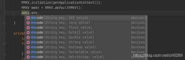
Mmkv use and principle

Docker deploy Oracle
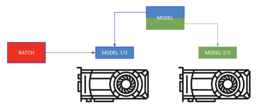
Pytorch model trains practical skills and breaks through the bottleneck of speed
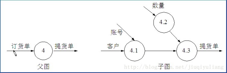
Data flow diagram, data dictionary
LeetCode每日一题(636. Exclusive Time of Functions)

一个程序员的水平能差到什么程度?尼玛,都是人才呀...

全球首款 RISC-V 笔记本电脑开启预售,专为元宇宙而生!
潘多拉 IOT 开发板学习(HAL 库)—— 实验12 RTC实时时钟实验(学习笔记)
EfficientNet模型的完整细节

The longest ascending subsequence model acwing 1012 Sister cities
随机推荐
解析PHP跳出循环的方法以及continue、break、exit的区别介绍
Data Lake (IX): Iceberg features and data types
Navigation — 这么好用的导航框架你确定不来看看?
C# 6.0 语言规范获批
The longest ascending subsequence model acwing 482 Chorus formation
昇腾体验官第五期随手记I
Base64 encoding
Small game design framework
2022 cloud consulting technology series high availability special sharing meeting
Oracle non automatic submission solution
Pytorch model trains practical skills and breaks through the bottleneck of speed
Cvpr2022 | backdoor attack based on frequency injection in medical image analysis
Electronic remote error
Horizontal of libsgm_ path_ Interpretation of aggregation program
LeetCode 648. 单词替换
Cocos creator direction and angle conversion
《微信小程序-进阶篇》组件封装-Icon组件的实现(一)
今日睡眠质量记录78分
LeetCode 648. Word replacement
JS in the browser Base64, URL, blob mutual conversion