当前位置:网站首页>[in simple terms, play with FPGA learning 3 ----- basic grammar]
[in simple terms, play with FPGA learning 3 ----- basic grammar]
2022-07-02 11:02:00 【Ape Zhou】
Play in depth FPGA Study 3----- Basic grammar
from Technology Map Viewer see 4 Input LUT
Most of the FPGA Is based on 4 Input LUT Structure , This article is through observation Quartus II Of Technology Map Viewer To explore 4 Input LUT.
The following code just implements a very simple 4 Input and function , The rising edge of each clock is latched once 4 Input and operation results are regarded as input .
// EX1A
input clk;   // The clock
input a,b,c,d;   //4 Input
output reg dout;   // Output
always @ (posedge clk)
	dout <= a&b&c&d;  //4 Input and
As shown in the figure , from Quartus II Of Technology Map Viewer It can be seen that this design consumes FPGA One inside 4 Input LUT And a trigger .
Let's see next 5 Input and operation
// EX2A
input clk;   // The clock
input a,b,c,d,e;   //5 Input
output reg dout;   // Output
always @ (posedge clk)
	dout <= a&b&c&d&e;  //4 Input and
How about the resource consumption after compilation ? As shown in the figure .
Two 4 Input LUT And a trigger , See this , You should understand FPGA Of 4 Enter the lookup table structure , Then you may wonder , Input b and c The one shared 4 Input LUT It seems that it hasn't been used up , There are two inputs left idle , Can it be reused ? Let's use another routine to see the answer to this question .
// EX3A
input clk;   // The clock
input a,b,c,d,e;   //5 Input
input f,g;
output reg dout;   //5 Input and output
output reg fout;    //2 Input or output
always @ (posedge clk) begin
	dout <= a&b&c&d&e;  //5 Input and
	fout <= f | g;      //2 Enter or
end
EX3A and EX2A Compared with the increase of one 2 Enter the logic of or , Will the system put this 2 Enter the desired LUT And not used up before LUT Reuse ?
As shown in the figure , Except for one more LUT Outside , There is also a trigger . In a combinatorial logic ( Such as :dout <= a&b&c&d&e) Not used up in LUT It cannot be reused by other logic .
This reminds people of the old topic : How to maximize FPGA Available resources for . Because of this 4 Input LUT The special structure of , Maybe sometimes the designer will try to make the input conditions meet 4 individual , In this way, we can make full use of existing resources . It's true , But there is absolutely no meaning to mislead everyone here , Most of the time, it is unnecessary and impossible to completely exhaust 4 Input LUT And modify the design ( You can't have both fish and bear paws , Maybe the resources in the design are fully utilized , But it may bring adverse effects on other aspects of the design ), This is just a pure discussion of this interesting lookup table structure .
About notes
Note the following about comments 3 spot :
1. Good comments can improve code maintainability . The main purpose of annotations is to significantly improve the maintainability of code .
2. Outdated or incorrect comments bring confusion to the code viewer , This is far worse than no comments . One of the biggest common mistakes in code annotation is , Comments describe only the functions implemented by the code itself . for example
addr <= addr + 1'b1; //addr Self increasing 1
This comment will not bring readers ( Code viewer ) Any information needed , The coder should tell the readers some information about the statement in the design they are not familiar with in the comments .
for example :( Assume that the project is FPGA And MCU signal communication )
addr <= addr + 1'b1; // stay MCU After writing a byte of data ,addr Self increasing 1, In order to offer MCU Read the next byte data
3. When writing comments to code , It should be assumed that the reader is an experienced engineer , He is familiar with Verilog The language itself , But I am not familiar with this project . The highest level of annotation is : Throw open source code , From the comments alone, we can understand the functions that the designer wants to achieve .
Reading Verilog A little experience of code
Learning a language depends on books alone , It needs more practice , Learn from small experiments step by step . Learning often needs to find some good code for reference .Verilog The parallelism of code brings a lot of inconvenience for beginners to digest other people's code , There is nothing wrong with small modules , Large modules and projects are sometimes difficult to start . because HDL The design of is different from software programming , Software is nothing more than a big main There is one in the function While Or some more interruptions , Most of them are executed in sequence , Step by step, you will always understand ;HDL The parallelism of is very strong , If we follow the idea of software, it will definitely not work .
since HDL Design is parallel , Then we can only break each one . For example, first grasp several important ports , Like the clock (CLOCK)、 Reset (RESET) And other ports with relatively high frequency , Make it clear , For example, what frequency is the clock 、 Is reset high effective or low effective , This is the most basic .
Then it is best to understand the code by referring to the requirements specification or task book of code engineering ( When the relevant documents are complete and the description is very detailed, it will be easy to read the code ), If none of this , Then only turn to the hardware schematic . This requires some basic hardware knowledge , The operation sequence of some commonly used devices must be well known , At least know one or two , In this way, we can get twice the result with half the effort when analyzing the code . For example, you should first understand FPGA And A/D The communication code of the chip , Well, first put A/D Each port of the chip ( Such as film selection 、 read / Write 、 Conversion enable 、 Ports such as interrupt after conversion ) stay Verilog Analyze everything that appears in the code , If looking for CS The signal , See when it pulls down effectively , So it can be Find in file Enter... In the window CS, And then go back , In this way, the development tool will list all uses in the underlying information window CS The statement of signal is convenient for finding and analyzing , Put every appearance CS All the places have been analyzed , Then you will understand Verilog How to operate on hardware CS The signal . After all the signals are analyzed , I understand this A/D Chip and FPGA The interface of .
Read Verilog Sometimes I'm tired , Because someone else wrote the code , It is also inevitable to let others lead by the nose , The key is to be patient , Analyze more , If you have conditions, you can ask more experts ( Preferably the author of the code ).
边栏推荐
- 二叉树专题--AcWing 3384. 二叉树遍历(已知先序遍历 边建树 边输出中序遍历)
- V2X-Sim数据集(上海交大&纽约大学)
- 【深入浅出玩转FPGA学习3-----基本语法】
- 【付费推广】常见问题合集,推荐榜单FAQ
- Dialogue Wu Gang: why do I believe in the rise of "big country brands"?
- Matlab processing of distance measurement of experimental electron microscope
- php中self和static在方法中的区别
- PCL point cloud to depth image
- Special topic of binary tree -- acwing 1589 Building binary search tree
- HDU1236 排名(结构体排序)
猜你喜欢
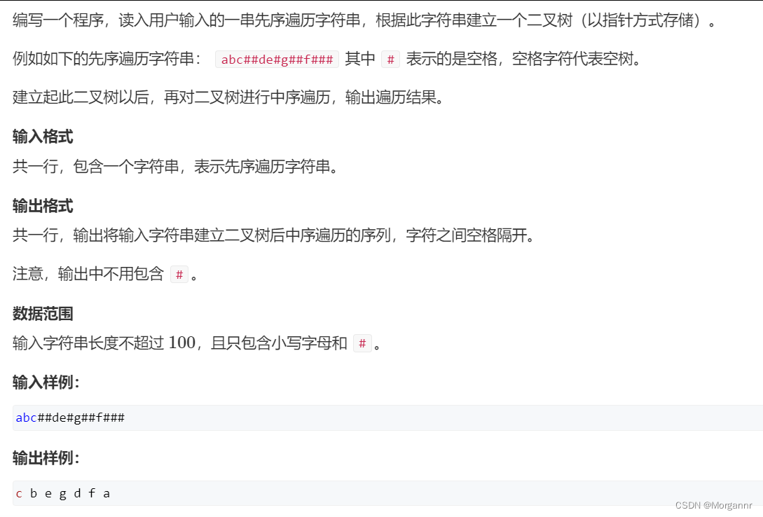
二叉树专题--AcWing 3384. 二叉树遍历(已知先序遍历 边建树 边输出中序遍历)

HDU1228 A + B(map映射)
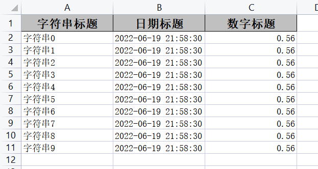
Easyexcel, a concise, fast and memory saving excel processing tool
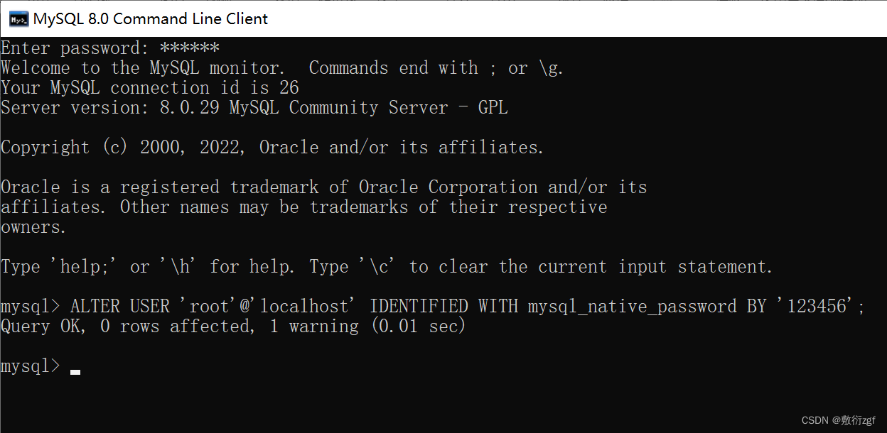
最详细MySql安装教程

一招快速实现自定义快应用titlebar

全网显示 IP 归属地,是怎么实现的?
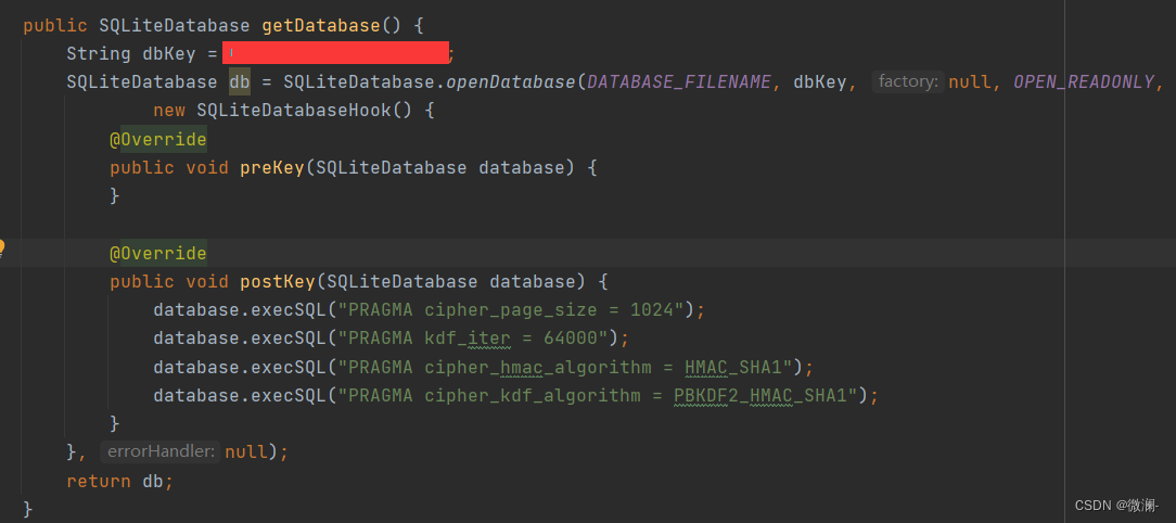
Open the encrypted SQLite method with sqlcipher
JSP webshell free -- the basis of JSP
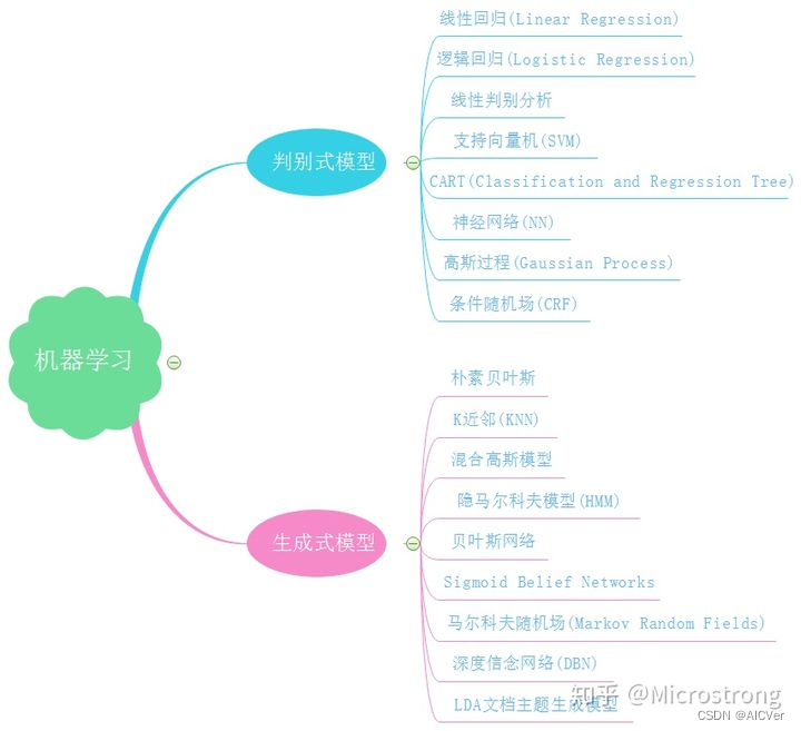
Overview of integrated learning
![2. Hacking lab script off [detailed writeup]](/img/f3/29745761cd5ad4df84c78ac904ea51.png)
2. Hacking lab script off [detailed writeup]
随机推荐
PCL projection point cloud
In the face of uncertainty, the role of supply chain
首份中国企业敏捷实践白皮书发布| 附完整下载
Set the playback speed during the playback of UOB equipment
PCL之K-d树与八叉树
V2X-Sim数据集(上海交大&纽约大学)
洛谷 P1892 [BOI2003]团伙(并查集变种 反集)
C#中索引器
Special topic of binary tree -- acwing 1589 Building binary search tree
UVM learning - build a simple UVM verification platform
PCL 从一个点云中提取一个子集
P1055 [noip2008 popularization group] ISBN number
HDU1234 开门人和关门人(水题)
Binary tree topic -- Luogu p3884 [jloi2009] binary tree problem (DFS for binary tree depth BFS for binary tree width Dijkstra for shortest path)
UVM - usage of common TLM port
Binary tree topic -- p1030 [noip2001 popularization group] find the first order
华为游戏初始化init失败,返回错误码907135000
二叉树专题--AcWing 47. 二叉树中和为某一值的路径(前序遍历)
【深入浅出玩转FPGA学习4----漫谈状态机设计】
Kustomize使用手册