当前位置:网站首页>Fuse bit of AVR study notes
Fuse bit of AVR study notes
2022-08-04 13:35:00 【uolian】
Fuse bit of AVR study notes
1. BOD (Brown-out Detection) power-down detection circuit
BODLEVEL (BOD level selection): 1: 2.7V level; 0: 4.0V level.This needs to be selected according to the operating voltage of the chip.
BODEN(BOD function control): 1: BOD function disabled; 0: BOD function enabled
How to use: If BODEN is enabled (check box is selected) to start power-down detection, the detection level is determined by BODLEVEL.Once the VCC drops below the trigger level (2.7v or 4.0v), the MCU resets; when the VCC level is greater than the trigger level, it starts to work again after the tTOUT delay cycle.
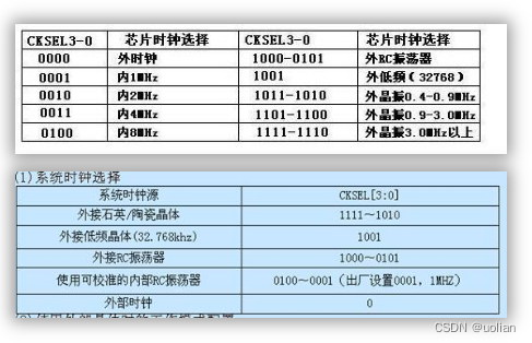
2. Reset startup time selection
SUT 1/0: When different crystal oscillators are selected, the SUT is different.If there are no special requirements, it is recommended that SUT 1/0 set the reset startup time to be slightly longer, so that the power supply rises slowly (ie SUT1: 1; SUT0: 0).
3, CKSEL3/2/10: Clock source selection.By default, CKSEL3-0, SUT1 and SYT0 are set to "0001" and "10" respectively, which will use the chip's 8mHz internal crystal oscillator and use the longest startup delay.
Configuration method:
4. M103: Set the ATmega103 compatible mode to work.The factory default setting is 0, which is to run in ATmega103 compatibility mode.
5. JTAGEN: If the JTAG interface is not used, the state of JTAGEN should be set to 1, that is, the JTAG function is disabled, and the JTAG pin is used for the I/O interface.
6, SPIEN: SPI mode download data and program permission, the default state is 0, generally keep its state.
7. WDTON: The watchdog timer is always on.The default is "1", which disables the watchdog timer from always on.Selecting "0" means that the watchdog timer is always on. It is recommended to set it to 0 to prevent the program from running away.
8. EESAVE: When EESAVE is set to "1", it means that when the chip is erased, the data in the flash and EEPROM will be erased together. If set to "0", the erase operation is only valid for the data in the flash.EEPROM is invalid.The factory default setting of the chip is "1".In practical applications, it needs to be set according to actual needs.
9. BOOTRST: Determines the address of the first instruction when it is powered on.The default state is "1", which means that the startup starts from 0x0000; if BOOTRST is set to "0", it starts from the starting position of BOOTLOADER (the first address of BOOTLOADER is determined by BOOTSZ1 and BOOTSZ0).
BOOTSZ1 and BOOTSZ0: These two bits determine the size and starting address of the BOOTLOADER.The default state is "00" for 4096 bytes, starting at 0xF000.
BOOLOADER area size configuration: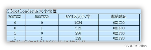
Note: inWhen setting the fuse bit, you must first determine whether "√" represents 1 or 0
边栏推荐
猜你喜欢

秋招攻略秘籍,吃透25个技术栈Offer拿到手软
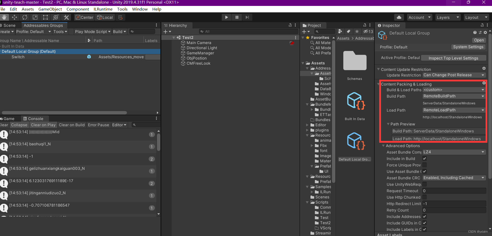
Unity 3D模型展示框架篇之资源打包、加载、热更(Addressable Asset System | 简称AA)

如何查找endnote文献中pdf文件的位置
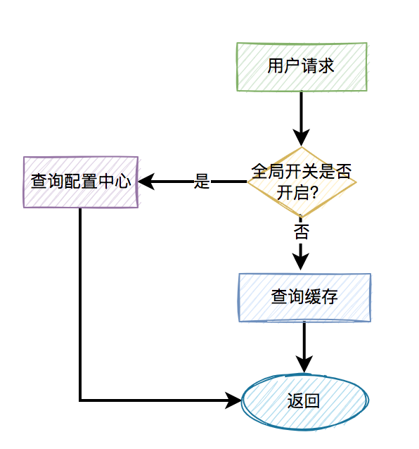
烂大街的缓存穿透、缓存击穿和缓存雪崩,你真的懂了?
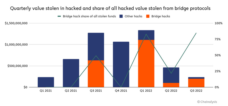
跨链桥已成行业最大安全隐患 为什么和怎么办
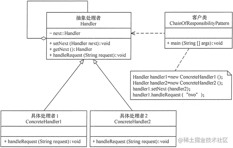
Is the code more messy?That's because you don't use Chain of Responsibility!
![[Niu Ke brush questions-SQL big factory interview questions] NO5. Analysis of a treasure store (e-commerce model)](/img/9f/33e782b93fcaa15359450e59a7233d.png)
[Niu Ke brush questions-SQL big factory interview questions] NO5. Analysis of a treasure store (e-commerce model)
![LeetCode 1403 Minimum subsequence in non-increasing order [greedy] HERODING's LeetCode road](/img/fd/c827608b96f678a67c7e920c51d8c5.png)
LeetCode 1403 Minimum subsequence in non-increasing order [greedy] HERODING's LeetCode road
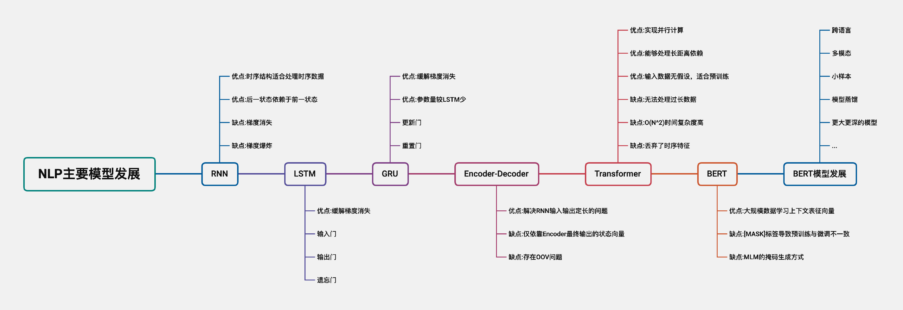
This article sorts out the development of the main models of NLP

CLS-PEG-DBCO,胆固醇-聚乙二醇-二苯基环辛炔,可用于改善循环时间
随机推荐
idea永久激活教程(新版)
21天学习挑战赛--第二天打卡(setSystemUiVisibility、导航栏、状态栏)
让Web页面中的编辑器支持黏贴或直接拖拽来添加图片「建议收藏」
router---mode
牛客网刷题记录 || 链表
odoo15 大部分模块都用的附件整理成一独立模块
【WeChat Mini Program】Social Internship Production Project for Information Management and Information System Major--Trash Fingerprint
Week 7 Latent Variable Models and Expectation Maximization
MySQL-数据类型
内存定位利器-ASAN使用小结
从零开始配置 vim(6)——缩写
Billboard
ROS设置plugin插件
关于mysql join 的一些说明
错误 AttributeError type object 'Callable' has no attribute '_abc_registry' 解决方案
LeetCode_424_替换后的最长重复字符
Programmer Qixi Gift - How to quickly build an exclusive chat room for your girlfriend in 30 minutes
Arduino框架下I2S控制ADC采样以及PWM输出示例解析
TS---类型设置
Map常见的遍历方式-keySet 和 entrySet