当前位置:网站首页>基于TI DRV10970驱动直流无刷电机
基于TI DRV10970驱动直流无刷电机
2022-07-05 14:33:00 【不会武功不懂江湖】
前言
之前在实验室接手了一个项目,需要使用TI的DRV10970芯片来驱动直流无刷电机带霍尔反馈,最近这几天把电机调通了,所以写个文章记录一下。
关于直流无刷电机的驱动方式,我也不过多赘述,CSDN上有很多,我只讲基于TI的DRV10970芯片来实现驱动直流无刷电机。
一、TI DRV10970
1.介绍
DRV10970是一款集成式三相BLDC电机驱动器,适用于家用电器、冷却风扇以及其他通用电机控制 应用。该器件内置智能特性,并且拥有小巧外形和简单的引脚分布结构,不仅降低了设计复杂度、节省了电路板空间,而且还降低了系统成本。集成的保护功能提高了系统的稳健性和可靠性。
这就意味着我们不需要去处理霍尔信号,芯片会自动来处理霍尔信号,我们只需要输出PWM和设置一些管脚便可以实现驱动直流无刷电机。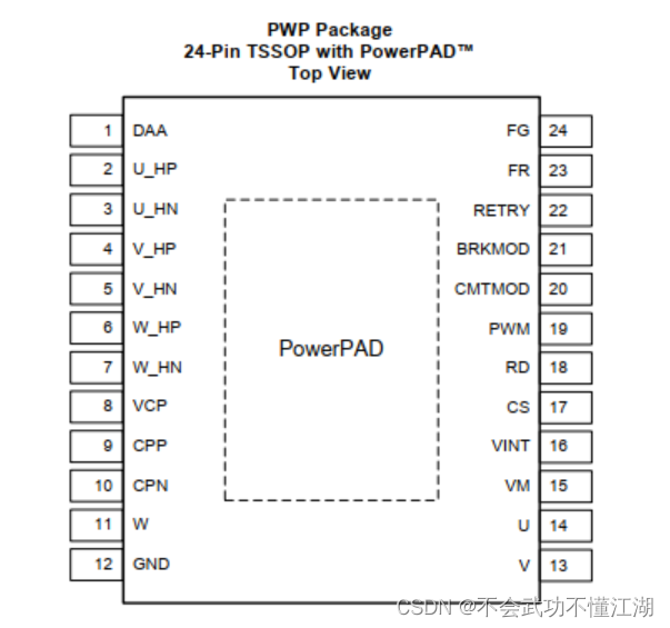
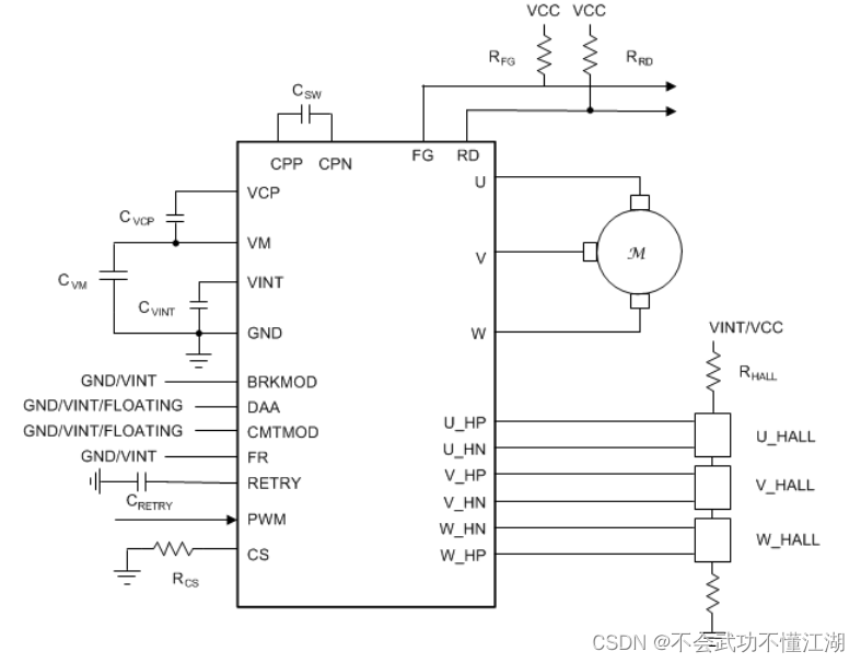
2.引脚介绍
| 名字 | 描述 |
|---|---|
| CPN | Charge pump switching node,Connect a 0.1-µF X7R capacitor rated for VM between CPN and CPP |
| CPP | Charge pump switching node,Connect a 0.1-µF X7R capacitor rated for VM between CPN and CPP |
| VCP | Charge pump output,Connect a 16-V, 1-µF ceramic capacitor to VM |
| GND | Device ground,Must be connected to board ground |
| VINT | Integrated regulator output,Integrated regulator (typical voltage 5 V) mainly for internal circuits; Provide external power for less than 20 mA. Bypass to GND with a 10-V, 2.2-µF ceramic capacitor |
| VM | Power supply |
| CS | Current limit setting pin |
| DAA | Drive angle adjustment configuration pin,Low: 10° drive angle adjustment,High: 5° drive angle adjustment,Floating: adaptive drive angle adjustment |
| FG | Frequency indication pin,Open drain Electrical Frequency Output pin. One toggle per electrical cycle. Requires an external pull-up of 3.3-kΩ. |
| FR | Motor direction control,Direction Control Input.When low, phase driving sequence is U → V → W ( U phase is leading V phase by 120°).When high, the phase driving sequence is U → W → V. |
| BRKMOD | Brake mode setting,Low: Coasting mode (phases are tri-stated),High: Brake mode (phases are driven low) |
| PWM | Variable duty cycle PWM input for speed control |
| RD | Lock indication pin |
| RETRY | Auto retry timing configure |
| CMTMOD | Commutation mode setting,Low: Sinusoidal operation mode with 0° Hall placement,High: Sinusoidal operation mode with 30° Hall placement,Floating: Trapezoidal operation mode with 30° Hall placement |
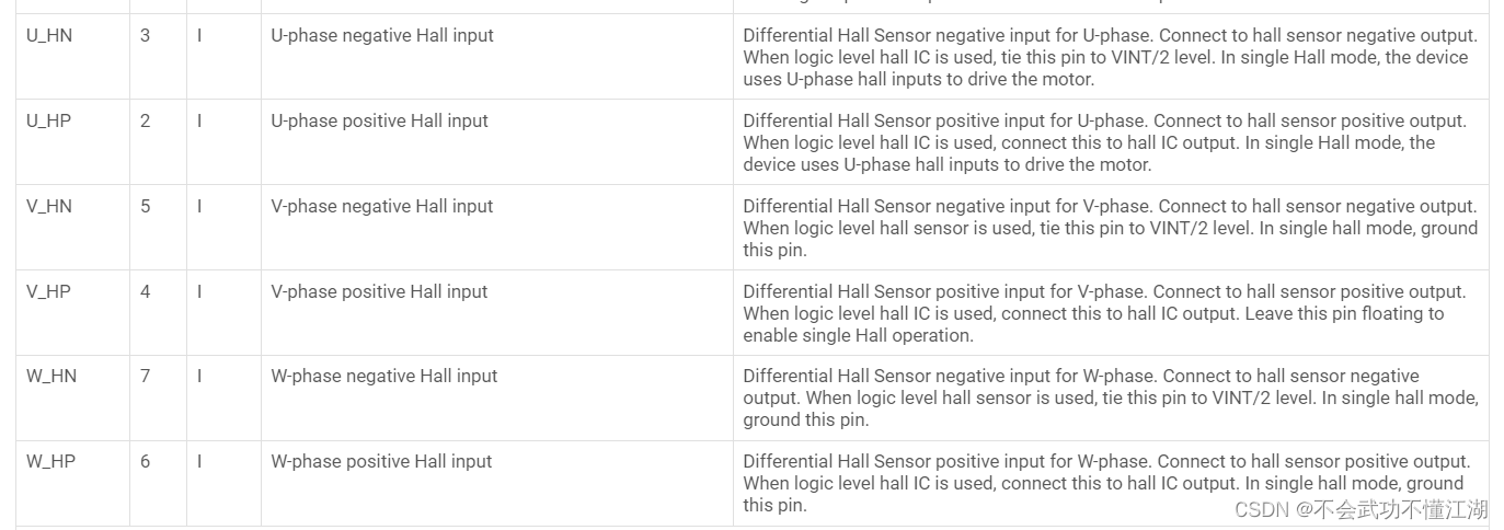
上面这么多引脚中我们只需要特别关注几个就好,其中包含脉宽调制 (PWM) 输入(速度命令)、FG 输出(速度反馈)、FR 输入(正向和反向控制)以及 RD 输出(电机锁定指示)。
FG和RD是DRV10970反馈给MCU的信号
CMTMOD是设置模式,一般将CMTMOD设置为低电平就是正弦模式0°放置霍尔元件,
BRKMOD是刹车模式设置,将BRKMOD引脚设置为低电平,即使把BRKMOD设置为高电平电机也不会刹车,因为这个管脚是设置刹车模式,而不是直接让电机刹车,只有断电或者将PWM设置为0才可以刹车。
DAA是驱动电机角度设置,设置为浮空即可,浮空就是自适应角度来驱动电机
PWM就是连接MCU的PWM输出管脚,PWM的频率为15Khz-100Khz。
二、使用步骤
1.程序
所以在使用DRV10970时,我们需要将PWM,FR,BM,CM,DAA设置好即可,我这里使用了两个芯片驱动两个电机
void PWM_Configuration(u16 arr,u16 pre)
{

	GPIO_InitTypeDef GPIO_InitStructure;
	TIM_TimeBaseInitTypeDef	TIM_TimeBaseStructure;
	TIM_OCInitTypeDef TIM_OCInitStructure;
// TIM_BDTRInitTypeDef TIM_BDTRInitStructure;

	RCC_AHB1PeriphClockCmd( RCC_AHB1Periph_GPIOA | RCC_AHB1Periph_GPIOB | RCC_AHB1Periph_GPIOC |RCC_AHB1Periph_GPIOD, ENABLE);
  RCC_APB1PeriphClockCmd(RCC_APB1Periph_TIM12, ENABLE);

	GPIO_PinAFConfig(GPIOB,GPIO_PinSource14,GPIO_AF_TIM12); //PB14 复用 TIM12
	GPIO_PinAFConfig(GPIOB,GPIO_PinSource15,GPIO_AF_TIM12); //PB14 复用 TIM12

	// PWM
	GPIO_InitStructure.GPIO_Pin =  GPIO_Pin_14 | GPIO_Pin_15;		 //
	GPIO_InitStructure.GPIO_Speed = GPIO_Speed_100MHz;
  GPIO_InitStructure.GPIO_Mode = GPIO_Mode_AF;
	GPIO_InitStructure.GPIO_OType = GPIO_OType_PP; //复用推挽输出
	GPIO_InitStructure.GPIO_PuPd = GPIO_PuPd_UP; //上拉
	GPIO_Init(GPIOB,&GPIO_InitStructure); //初始化 PB14

	//M1
	//GPIO DAA 悬空 M2 PD14--DAA
	GPIO_InitStructure.GPIO_Pin =  GPIO_Pin_8 | GPIO_Pin_14 ;
	GPIO_InitStructure.GPIO_Mode = GPIO_Mode_IN;//普通输入模式
	GPIO_InitStructure.GPIO_OType = GPIO_OType_PP;//
	GPIO_InitStructure.GPIO_Speed = GPIO_Speed_100MHz;//100MHz
	GPIO_InitStructure.GPIO_PuPd = GPIO_PuPd_NOPULL;//浮空
	GPIO_Init(GPIOD, &GPIO_InitStructure);//初始化GPIOD

	GPIO_InitStructure.GPIO_Pin = GPIO_Pin_8 ;	 //GPIO_Pin_11
	GPIO_InitStructure.GPIO_Mode = GPIO_Mode_OUT;//普通输出模式
	GPIO_InitStructure.GPIO_OType = GPIO_OType_PP;//推挽输出
	GPIO_InitStructure.GPIO_Speed = GPIO_Speed_100MHz;//100MHz
	GPIO_InitStructure.GPIO_PuPd = GPIO_PuPd_UP;//上拉
	GPIO_Init(GPIOB, &GPIO_InitStructure);//初始化GPIOD

			//GPIO M1--PD12--CM
	GPIO_InitStructure.GPIO_Pin = GPIO_Pin_12 | GPIO_Pin_15 ;	 //M2 PD15--FR
	GPIO_InitStructure.GPIO_Mode = GPIO_Mode_OUT;//普通输出模式
	GPIO_InitStructure.GPIO_OType = GPIO_OType_PP;//推挽输出
	GPIO_InitStructure.GPIO_Speed = GPIO_Speed_100MHz;//100MHz
	GPIO_InitStructure.GPIO_PuPd = GPIO_PuPd_UP;//上拉
	GPIO_Init(GPIOD, &GPIO_InitStructure);//初始化GPIOD

				//GPIO M2--PA12--CM M2-PA11-BM
	GPIO_InitStructure.GPIO_Pin = GPIO_Pin_11 | GPIO_Pin_12 ;
	GPIO_InitStructure.GPIO_Mode = GPIO_Mode_OUT;//普通输出模式
	GPIO_InitStructure.GPIO_OType = GPIO_OType_PP;//推挽输出
	GPIO_InitStructure.GPIO_Speed = GPIO_Speed_100MHz;//100MHz
	GPIO_InitStructure.GPIO_PuPd = GPIO_PuPd_UP;//上拉
	GPIO_Init(GPIOA, &GPIO_InitStructure);//初始化GPIOD

	//GPIO //FG and RD all feedback
	GPIO_InitStructure.GPIO_Pin =  GPIO_Pin_9|  GPIO_Pin_13;	//输入
	GPIO_InitStructure.GPIO_Mode = GPIO_Mode_IN;//普通输入模式
	GPIO_InitStructure.GPIO_Speed = GPIO_Speed_100MHz;//100MHz
	GPIO_InitStructure.GPIO_PuPd = GPIO_PuPd_UP;//
	GPIO_Init(GPIOD, &GPIO_InitStructure);//初始化GPIOD

		//GPIO // M2--PC8--RD M2--FG--PC14
	GPIO_InitStructure.GPIO_Pin = GPIO_Pin_8 | GPIO_Pin_14;	//输入
	GPIO_InitStructure.GPIO_Mode = GPIO_Mode_IN;//普通输入模式
	GPIO_InitStructure.GPIO_Speed = GPIO_Speed_100MHz;//100MHz
	GPIO_InitStructure.GPIO_PuPd = GPIO_PuPd_UP;//
	GPIO_Init(GPIOC, &GPIO_InitStructure);//初始化GPIOD

	//GPIO // CMTMOD--PD10
	GPIO_InitStructure.GPIO_Pin =  GPIO_Pin_10|GPIO_Pin_11;	//输入
	GPIO_InitStructure.GPIO_Mode = GPIO_Mode_OUT;//普通输入模式
	GPIO_InitStructure.GPIO_Speed = GPIO_Speed_100MHz;//100MHz
	GPIO_InitStructure.GPIO_PuPd = GPIO_PuPd_DOWN;//
	GPIO_Init(GPIOD, &GPIO_InitStructure);//初始化GPIOD


	TIM_TimeBaseStructure.TIM_Period= arr-1;
	TIM_TimeBaseStructure.TIM_Prescaler= pre-1;
	TIM_TimeBaseStructure.TIM_CounterMode=TIM_CounterMode_Up;
	TIM_TimeBaseStructure.TIM_ClockDivision=TIM_CKD_DIV1;
	TIM_TimeBaseInit(TIM12,&TIM_TimeBaseStructure);	 //TIM12

	TIM_OCInitStructure.TIM_OCMode = TIM_OCMode_PWM1;
	TIM_OCInitStructure.TIM_OutputState = TIM_OutputState_Enable;
	TIM_OCInitStructure.TIM_OCPolarity = TIM_OCPolarity_High;

// TIM_DeInit(TIM12);

	TIM_OC1Init(TIM12, &TIM_OCInitStructure);//初始化外设TIM1 OC1--OC4
	TIM_OC2Init(TIM12, &TIM_OCInitStructure);
	TIM_OC3Init(TIM12, &TIM_OCInitStructure);
	TIM_OC4Init(TIM12, &TIM_OCInitStructure);

	TIM_OC1PreloadConfig(TIM12, TIM_OCPreload_Enable);//使能预装载寄存器
	TIM_OC2PreloadConfig(TIM12, TIM_OCPreload_Enable);
  TIM_OC3PreloadConfig(TIM12, TIM_OCPreload_Enable);
	TIM_OC4PreloadConfig(TIM12, TIM_OCPreload_Enable);

	TIM_ARRPreloadConfig(TIM12,ENABLE);

	TIM_Cmd(TIM12, ENABLE);

	//M1
	// PD12--CM
	GPIO_ResetBits(GPIOD, GPIO_Pin_10 );//PD10---FR PD11---BM

	GPIO_SetBits(GPIOD, GPIO_Pin_12 );// PD12--CM

	//M2
	GPIO_ResetBits(GPIOA, GPIO_Pin_11 );// PA11--BM
	GPIO_SetBits(GPIOA, GPIO_Pin_12 );// PD12--CM

}
三.如何判断芯片时候损坏
当VM供12V电时,如果VINT没有5V输出,就可以认为芯片坏了
边栏推荐
- Intelligent supply chain collaboration system solution for daily chemical products industry: digital intelligent SCM supply chain, which is the "acceleration" of enterprise transformation
- How to protect user privacy without password authentication?
- Disjoint Set
- 快消品行业SaaS多租户解决方案,构建全产业链数字化营销竞争力
- Why do mechanical engineers I know complain about low wages?
- Thymeleaf th:with局部变量的使用
- 面试突击62:group by 有哪些注意事项?
- R language ggplot2 visual bar graph: visualize the bar graph through the two-color gradient color theme, and add label text for each bar (geom_text function)
- Enjoy what you want. Zhichuang future
- 03_ Dataimport of Solr
猜你喜欢
CPU设计相关笔记
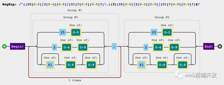
Sharing the 12 most commonly used regular expressions can solve most of your problems

Shen Ziyu, nouveau Président de Meizu: M. Huang Zhang, fondateur de Meizu, agira comme conseiller stratégique pour les produits scientifiques et technologiques de Meizu

用 Go 跑的更快:使用 Golang 为机器学习服务
Implement a blog system -- using template engine technology
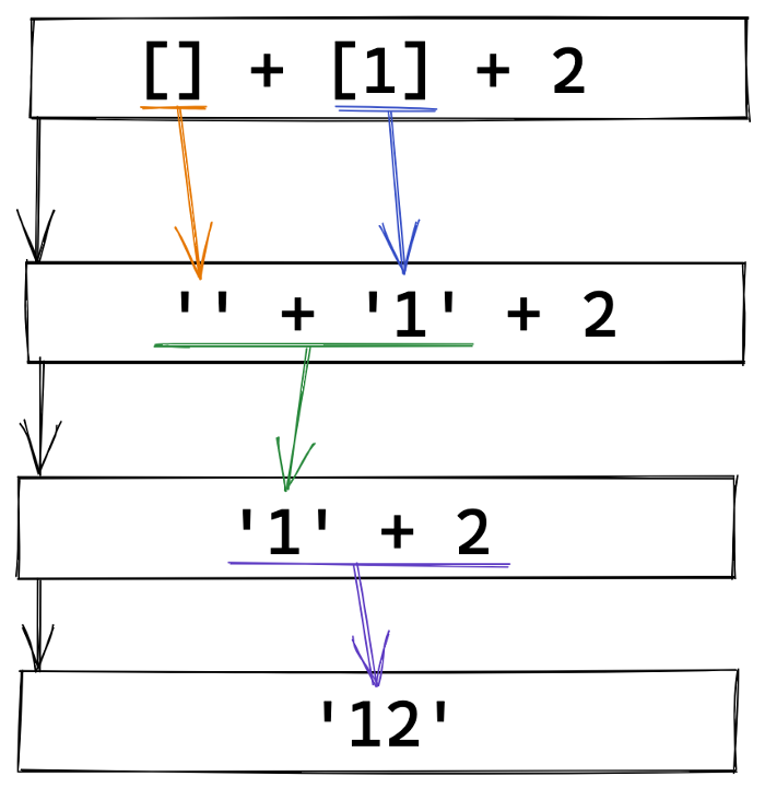
Share 20 strange JS expressions and see how many correct answers you can get

Solution of commercial supply chain collaboration platform in household appliance industry: lean supply chain system management, boosting enterprise intelligent manufacturing upgrading

How to choose the appropriate certificate brand when applying for code signing certificate?

PyTorch二分类时BCELoss,CrossEntropyLoss,Sigmoid等的选择和使用
Topology可视化绘图引擎
随机推荐
Chow Tai Fook fulfills the "centenary commitment" and sincerely serves to promote green environmental protection
After the microservice project is deployed, static resources and files uploaded to upload cannot be accessed. Solution
SaaS multi tenant solution for FMCG industry to build digital marketing competitiveness of the whole industry chain
Shen Ziyu, nouveau Président de Meizu: M. Huang Zhang, fondateur de Meizu, agira comme conseiller stratégique pour les produits scientifiques et technologiques de Meizu
Principle and performance analysis of lepton lossless compression
Thymeleaf 模板的创建与使用
R language uses the polR function of mass package to build an ordered multi classification logistic regression model, and uses the coef function to obtain the log odds ratio corresponding to each vari
Lepton 无损压缩原理及性能分析
CPU设计实战-第四章实践任务二用阻塞技术解决相关引发的冲突
How to call the function mode of one hand and one machine
R语言ggplot2可视化条形图:通过双色渐变配色颜色主题可视化条形图、为每个条形添加标签文本(geom_text函数)
C语言中限定符的作用
dynamic programming
Fonctions communes de thymeleaf
Implement a blog system -- using template engine technology
How to choose the appropriate certificate brand when applying for code signing certificate?
超级哇塞的快排,你值得学会!
[learning notes] connectivity and circuit of graph
C language -- structure and function
CyCa children's physical etiquette Ningbo training results assessment came to a successful conclusion