当前位置:网站首页>The concepts of terminal voltage, phase voltage and line voltage in FOC vector control and BLDC control are still unclear
The concepts of terminal voltage, phase voltage and line voltage in FOC vector control and BLDC control are still unclear
2022-07-02 23:12:00 【strongerHuang】
limit 300 name ,1.99 receive BLDC Motor drive control algorithm learning video (24-31 Ministry )
limit 300 name , Scan the QR code below to add the customer service little sister ( Be sure to add a friend note STM)

One 、 Preface
In the process of teaching , It is found that some students have terminal voltage 、 Phase voltage 、 The concept of line voltage is vague , So this article intends to introduce these three concepts in detail , And use the actual waveform to show you the terminal voltage under different control modes 、 Phase voltage 、 What is the actual waveform of line voltage , In order to achieve the purpose of making these concepts no longer vague .
Figure 1 below shows three-phase inverter bridge and three-phase permanent magnet synchronous motor ( When interpreting the square wave control waveform, it is also equivalent to DC brushless motor ) Connection diagram , The concepts given later , Refer to the label definition in the figure .
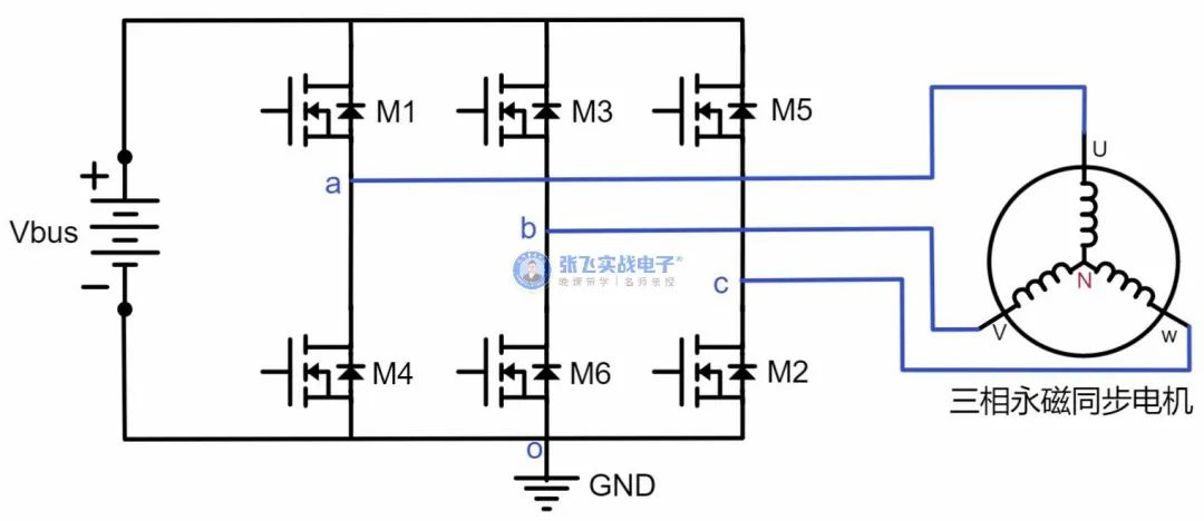
Figure 1 : Schematic diagram of connection between three-phase inverter bridge and three-phase permanent magnet synchronous motor
Two 、 terminal voltage 、 Phase voltage 、 Introduction to the concept of line voltage
On the Internet , There are a lot of data, and the concept description of terminal voltage and phase voltage is very vague , Even the concepts of terminal voltage and phase voltage are sometimes confused , The following is an introduction to the concept of three voltages , And show it in the form of pictures , To help you impress .
terminal voltage : In the connection diagram of three-phase inverter bridge and three-phase permanent magnet synchronous motor , Three phase line (U,V,W) Relative to the reference point o The measured voltage is called terminal voltage .
In Figure 2 below ,Uao,Ubo,Uco It means three-phase terminal voltage .
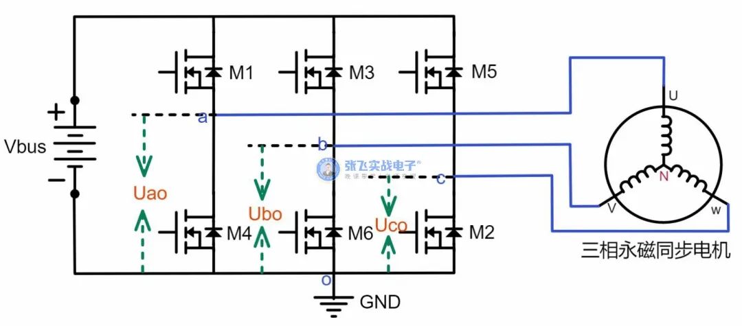
Figure 2 : Schematic diagram of three-phase terminal voltage measurement
Phase voltage : In the connection diagram of three-phase inverter bridge and three-phase permanent magnet synchronous motor , Three phase line (U,V,W) Relative to the motor star connection point N The measured voltage is called phase voltage .
In Figure 3 below ,UaN,UbN,UcN It means three-phase voltage .
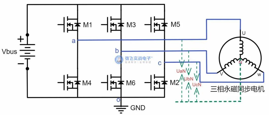
Figure 3 : Schematic diagram of three-phase voltage measurement
But generally, the star connection point of motor N Will not lead out , Therefore, generally speaking, it is impossible to directly measure the phase voltage . If you want to see the phase voltage waveform , The star connection point can be simulated with a resistance much larger than the phase resistance of the motor , Measure the three-phase line U,V,W Relative to the simulated star connection point N1 The voltage of , It can also reflect the phase voltage equivalently . Therefore, figure 4 below is the schematic diagram of virtual Star point measuring equivalent phase voltage .
In Figure 4 below ,UaN1,UbN1,UcN1 It means three-phase equivalent phase voltage .

Figure 4 : Schematic diagram of three-phase equivalent phase voltage measurement
Line voltage : In the connection diagram of three-phase inverter bridge and three-phase permanent magnet synchronous motor , Three phase line (U,V,W) The voltage measured by taking any two phase lines is called line voltage .
In Figure 5 below ,Uab,Ubc,Uca It means the voltage of three lines .

Figure 5 : Schematic diagram of three-phase equivalent line voltage measurement
3、 ... and 、 Terminal voltage measured under different control modes 、 Line voltage 、 Phase voltage waveform
1. Square wave control , Measured terminal voltage waveform 、 Line voltage waveform 、 Phase voltage waveform
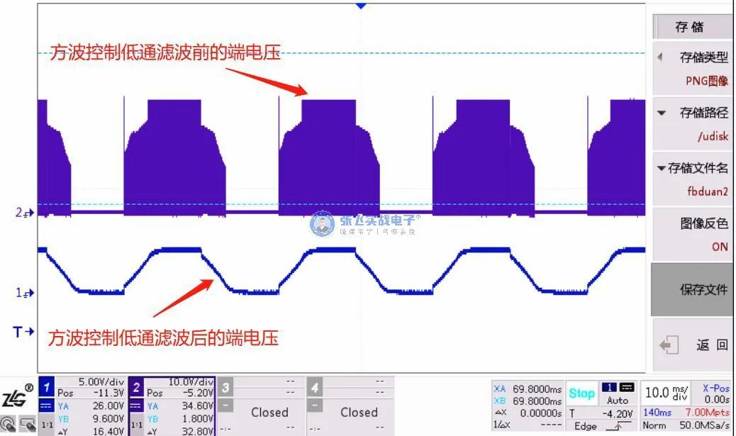
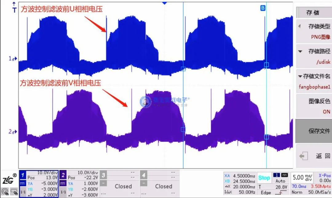
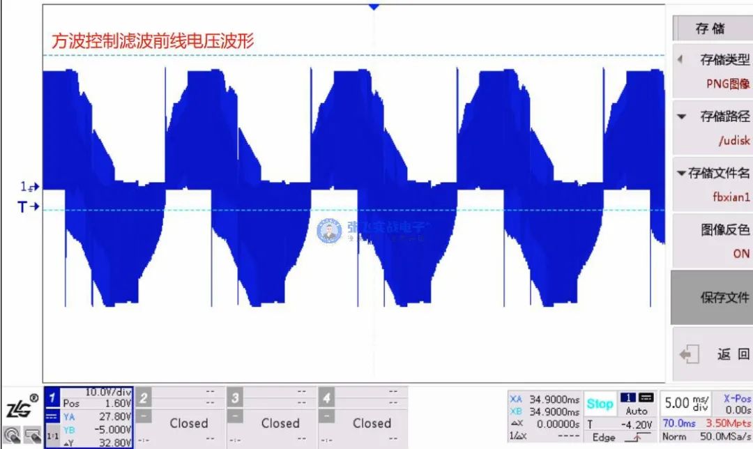
 Figure 6 : Waveform measurement diagram of square wave control terminal voltage and line voltage
From the waveform , Before filtering , Because the switch tube is PWM The control of the , So the terminal voltage waveform 、 The waveform of phase voltage and line voltage contains switching chopper , After filtering , It can be seen that the terminal voltage is a trapezoidal wave , The filtered line voltage is also trapezoidal wave
Because there is no filter circuit in the measuring circuit , Therefore, only the phase voltage waveform before filtering is shown here .
2. SPWM Control time , Measured terminal voltage waveform 、 Line voltage waveform


Figure 7 :SPWM Measurement diagram of voltage waveform at control terminal
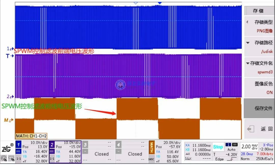
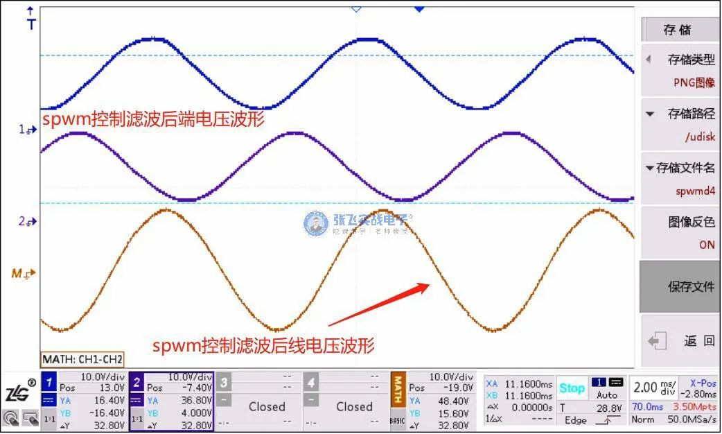
Figure 8 :SPWM Control line voltage waveform measurement diagram
SPWM In the control , From the measurement waveform , Terminal voltage and line voltage also contain switching chopper , Observe by expanding the waveform , The terminal voltage waveform is a pulse wave with gradually changing pulse width , The filtered terminal voltage and line voltage are sine waves , And because the phase voltage and line voltage are only different in amplitude , So we can also get SPWM The controlled phase voltage is also a sine wave .
therefore ,SPWM In the control , terminal voltage 、 Phase voltage 、 The line voltages are sine waves , However, observing these waveforms requires low-pass filtering of the original measured waveform .
3. SVPWM Control time , Measured terminal voltage waveform 、 Line voltage waveform
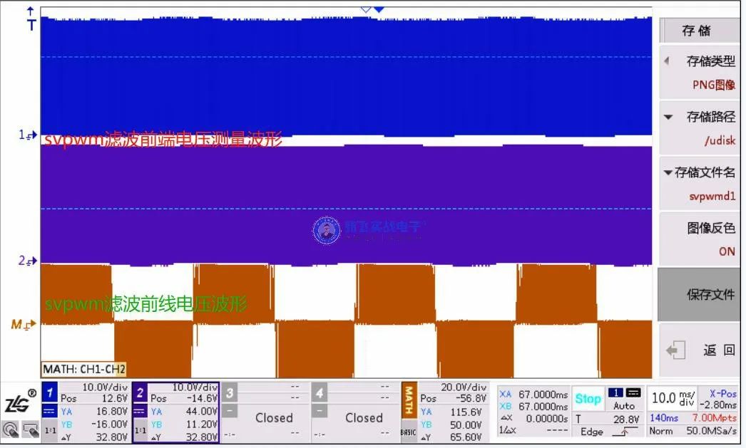

Figure nine :svpwm Waveform measurement diagram of control terminal voltage and line voltage
SVPWM In the control , From the measurement waveform , Terminal voltage and line voltage also contain switching chopper , The filtered terminal voltage is a saddle wave , The line voltage is a sine wave , And because the phase voltage and line voltage are only different in amplitude , So we can also get SVPWM The controlled phase voltage is also a sine wave .
therefore ,SVPWM In the control , The terminal voltage is a saddle wave 、 Phase voltage 、 The line voltages are sine waves , However, observing these waveforms requires low-pass filtering of the original measured waveform .
Of course , The relationship between these waveforms , It can also be derived from relevant mathematical derivation , Those who are willing can deduce by themselves , You can also pay attention to Zhang Fei's actual combat Electronics FOC The motor drive line goes to work , There will be detailed explanations in the course .
Four 、 summary
This article , Through the terminal voltage 、 Phase voltage 、 Introduction of three concepts of line voltage , Try to make everyone not to confuse these three concepts . And there are also many engineers on the terminal voltage under different control modes 、 Phase voltage 、 The line voltage waveform is not very clear , This paper also passes the actual waveform test , The corresponding waveform diagrams of the three are shown for you .
I hope that after reading this article , We will encounter similar problems in the future , It is easy to say the test method of these waveforms and the corresponding waveform shape .
This article , Just share so much , Share more knowledge about the original motor drive , Welcome to continue to pay attention to Zhang Fei's actual combat Electronics !
limit 300 name ,1.99 receive BLDC Motor drive control algorithm learning video (24-31 Ministry )
limit 300 name , Scan the QR code below to add the customer service little sister ( Be sure to add a friend note STM)
边栏推荐
- Jericho's thimble reaction when directly touching the prototype is abnormal [chapter]
- Jerry's built-in shutdown current is 1.2ua, and then it can't be turned on by long pressing [chapter]
- Pandora IOT development board learning (HAL Library) - Experiment 4 serial port communication experiment (learning notes)
- 海思3559万能平台搭建:在截获的YUV图像上画框
- 成功改变splunk 默认URL root path
- 海思3559万能平台搭建:在截获的YUV图像上旋转操作
- Jerry's prototype has no touch, and the reinstallation becomes normal after dismantling [chapter]
- Loss function~
- [Solved] Splunk: Cannot get username when all users are selected“
- 提交代码流程
猜你喜欢

Lambda表达式:一篇文章带你通透

Successfully changed Splunk default URL root path

Data analysis learning records -- complete a simple one-way ANOVA with Excel
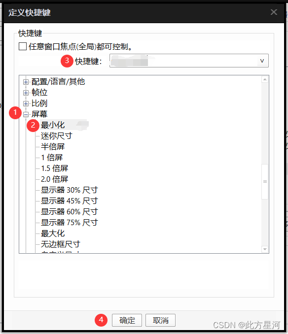
PotPlayer设置最小化的快捷键
![[chestnut sugar GIS] ArcScene - how to make elevation map with height](/img/91/f3df0a7633263c6264cb5c27eb149f.png)
[chestnut sugar GIS] ArcScene - how to make elevation map with height

QT qpprogressbar details
![[npuctf2020]ezlogin XPath injection](/img/6e/dac4dfa0970829775084bada740542.png)
[npuctf2020]ezlogin XPath injection
![[Yangcheng cup 2020] easyphp](/img/12/da28f738e50e625b0a66a94af3703d.png)
[Yangcheng cup 2020] easyphp

Chow-Liu Tree
Chow-Liu Tree
随机推荐
Call vs2015 with MATLAB to compile vs Project
Is 408 not fragrant? The number of universities taking the 408 examination this year has basically not increased!
[Solved] Splunk: Cannot get username when all users are selected“
C#中Linq用法汇集
剑指 Offer II 099. 最小路径之和-双百代码
pytorch训练CPU占用持续增长(bug)
ServletContext learning diary 1
Antd component upload uploads xlsx files and reads the contents of the files
AES高級加密協議的動機闡述
MySQL queries nearby data And sort by distance
数字图像处理实验目录
Lc173. Binary search tree iterator
Mask R-CNN
Tiktok actual combat ~ number of likes pop-up box
Catalogue of digital image processing experiments
Troubleshooting the cause of the crash when STM32 serial port dam receives 253 bytes
MySQL reset password, forget password, reset root password, reset MySQL password
力扣刷题(2022-6-28)
Niuke network: maximum submatrix
[Yangcheng cup 2020] easyphp