当前位置:网站首页>Difference and application of SPI, UART and I2C communication
Difference and application of SPI, UART and I2C communication
2022-06-12 07:15:00 【Snow falls on the devil's land】
Communication between electronic devices is like communication between humans , Both sides need to speak the same language . In Electronics , These languages are called communication protocols .
I've shared it alone before SPI、UART、I2C Communication articles , This article makes some comparisons between them .
Serial VS parallel
Electronic devices talk to each other by sending data bits . Bits are binary , Can only be 1 or 0. Through the rapid change of voltage , Bits are transferred from one device to another . In order to 5V In the working system ,“0” adopt 0V Short pulses of communication , and “1” adopt 5V Short pulses of communication .
Data bits can be transmitted in parallel or serial form . You can also learn about... Through this video : Video Explanation UART、I2C、SPI Serial port communication . In parallel communication , Data bits are transmitted simultaneously on the wire . The figure below shows binary (01000011) Middle letter “C” Parallel transmission of :

In serial communication , Bits are sent one by one over a single wire . The figure below shows binary (01000011) Middle letter “C” Serial transmission of :

SPI signal communication
SPI It is a common device general communication protocol . It has a unique advantage that it can transmit data without interruption , Any number of bits can be continuously transmitted or received . And in the I2C and UART in , Data is sent in packets , With a limited number of digits .
stay SPI In the device , Equipment is divided into master and slave systems . The host is a control device ( It's usually a microcontroller ), And the slave ( It's usually a sensor , Display or memory chip ) Get instructions from the host .
A set of SPI The communication consists of four signal lines :MOSI (Master Output/Slave Input) – The signal line , Host output , Slave input .MISO (Master Input/Slave Output) – The signal line , Host input , Slave output .SCLK (Clock) – Clock signal .SS/CS (Slave Select/Chip Select) – Piece of optional signal .

SPI Characteristics of the agreement
actually , The number of slaves is limited by the system load capacitance , It will reduce the ability of the host to accurately switch between voltage levels .
Clock signal
One bit of data per clock cycle , So the speed of data transmission depends on the frequency of the clock signal . The clock signal is generated by the host configuration , therefore SPI Communication is always initiated by the host .
Any communication protocol in which devices share clock signals is called synchronization .SPI It's a synchronous communication protocol , There are also asynchronous communications that do not use clock signals . For example, in UART In communication , Both sides are set to the pre configured baud rate , The baud rate determines the speed and timing of data transmission .
Piece of optional signal
The master pulls down the slave CS/SS Enable communication . At leisure / In the non transmission state , The chip selection line remains high . There can be multiple on the host CS/SS Pin , Allow the host to communicate with multiple different slaves .
Uploading … Re upload cancel
If the host has only one chip select pin available , These slave devices can be connected in the following ways :

MOSI and MISO
The host by MOSI Send data to the slave in serial mode , The slave can also pass through MISO Send data to the host , Both can be done at the same time . So theoretically ,SPI It is a full duplex communication protocol .
Transmission steps
1. Host output clock signal

2. The main engine is pulled down SS / CS Pin , Activate slave

3. The host by MOSI Send data to the slave

4. If you need a response , Then the slave passes MISO Return the data to the host

Use SPI There are some advantages and disadvantages , If you choose between different communication protocols , Then it shall be fully considered according to the project requirements .
SPI advantage
SPI Communication has no start and stop bits , So the data can flow continuously without interruption ; Didn't like I2C Such a complex slave addressing system , The data transmission rate ratio is I2C Higher ( Almost twice as fast ). independent MISO and MOSI line , Can send and receive data at the same time .
SPI shortcoming
SPI Use four wires (I2C and UART Use two wires ), No confirmation of successful signal reception (I2C With this feature ), There's no form of error checking ( Such as UART Parity bits in ).

UART Stands for universal asynchronous receiver / The transmitter is also called serial communication , It is not like SPI and I2C Such a communication protocol , It's a physical circuit in the microcontroller or an independent IC.
UART The main purpose of is to send and receive serial data , Its best advantage is that it uses only two lines to transmit data between devices .UART The principle of is easy to understand , But if you haven't read SPI Communication protocol , That may be a good starting point .
UART signal communication
stay UART In communication , Two UART Communicate directly with each other . send out UART Control the equipment ( Such as CPU) The parallel data is converted to serial form , It is sent serially to the receiver UART. Only two lines are needed to work in two UART Transfer data between , Data is sent from UART Of Tx The pin flows to the receiver UART Of Rx Pin :

UART It belongs to asynchronous communication , This means that there is no clock signal , Instead, add start and stop bits to the packet . These bits define the beginning and end of the packet , So receive UART Know when to read this data .
When receiving UART When the start bit is detected , It will read at a specific baud rate . Baud rate is a measure of data transmission speed , In bits per second (bps) Express . Two UART Must operate at approximately the same baud rate , Send and receive UART The baud rate difference between can only be about 10%.

UART working principle
send out UART After obtaining parallel data from the data bus , It adds a start bit , A parity bit and a stop bit are used to form a packet and start from Tx Bit by bit serial output on the pin , receive UART In its Rx Read the packet bit by bit on the pin .

UART The packet contains 1 Starting bits ,5 to 9 Data bits ( Depending on UART), An optional parity bit and 1 Or 2 Stop bits :

Start bit :
UART The data transmission line is usually maintained at a high voltage level when data is not transmitted . Send when transmission starts UART Pull the transmission line from high level to low level in one clock cycle , When receiving UART When a high to low voltage transition is detected , It starts reading bits in the data frame at baud rate .
Data frame :
The data frame contains the actual data being transmitted . If parity bits are used , It can be 5 position , most 8 position . If you don't use parity bits , Then the length of the data frame can be 9 position .
Check bit :
The parity bit is received UART How to determine whether there is any data change during transmission . receive UART After reading the data frame , It will have a pair value of 1 Count the number of bits , And check whether the total number is even or odd , Whether it matches the data .
Stop bit :
To signal the end of a packet , send out UART Drive the data transmission line from low voltage to high voltage for at least two bits .
Transmission steps
1. send out UART Receive data in parallel from the data bus :

2. send out UART Set start bit , Parity bits and stop bits are added to the data frame :

3. The whole packet is sent from UART Serial send to receive UART. receive UART The data line is sampled at a pre configured baud rate :

4. receive UART Discard the start bit in the data frame , Parity bit and stop bit :

5. receive UART Converting serial data back to parallel data , And transmit it to the data bus at the receiving end :

No communication protocol is perfect , however UART Very good at their work . Here are some pros and cons , Can help you determine if they are suitable for your project needs :
advantage
Use only two wires
No clock signal needed
Have parity bits to allow error checking
As long as both sides set up the packet structure
Well documented and widely used methods
shortcoming
The maximum size of the data frame is 9 position
Multiple slave systems or multiple master systems are not supported
Every UART The baud rate must be within each other's 10% within
I2C signal communication
I2C The bus is made up of Philips The company developed a simple 、 Two way two wire synchronous serial bus . It only needs two wires to transmit information . It is a combination of SPI and UART The advantages of , You can connect multiple slaves to a single host ( Such as SPI like that ), Multiple hosts can also be used to control one or more slaves . When you want multiple microcontrollers to record data to a single memory card or display text to a single memory card LCD when , This will be very useful .

SDA (Serial Data) – cable .
SCL (Serial Clock) – Clock line .
I2C It's a serial communication protocol , So the data goes along SDA Bit by bit . And SPI equally ,I2C A clock synchronization signal is also required and the clock is always controlled by the host .

working principle
I2C The data transmission is based on multiple msg In the form of , Every msg Contains the binary address frame of the slave , And one or more data frames , It also includes start conditions and stop conditions , read / Between write bits and data frames ACK / NACK position :

Starting conditions : When SCL It's high level ,SDA Switch from high level to low level .
Stop conditions : When SCL It's high level ,SDA Switch from low level to high level .

Address frame : Unique to each slave 7 Bit or 10 Bit sequence , Used for address identification between master and slave devices .
read / Write in : a , If the master sends data to the slave, it is low , The request data is high .
ACK/NACK: Each frame in the message is followed by a ACK/NACK position . If the address frame or data frame is successfully received , The receiving device will return a ACK Bits are used to indicate confirmation .
Addressing
because I2C Didn't like SPI That kind of film selection line , Therefore, it needs to use another way to confirm a slave device , And this way is —— Addressing .
The host sends the slave address to be communicated to each slave , Then each slave compares it with its own address . If the address matches , It will send a low level to the host ACK position . If it doesn't match , Do nothing ,SDA The line remains high .
read / Write in
The end of the address frame contains a read / Write in . If the master wants to send data to the slave , Low level . If the master requests data from the slave , High level .
Data frame
When the host detects the of the slave ACK Behind you , You can send the first data frame . The data frame is always 8 position , Each data frame is followed by ACK / NACK position , To verify the reception status . When all data frames are sent , The master can send a stop condition to the slave to terminate the communication .
Transmission steps
1. stay SCL The line is at high level , The host will SDA The line switches from high level to low level to start bus communication .
2. The master sends to the bus the information of the slave to communicate with 7 Bit or 10 Bit address , And reading / Write in :

3. Each slave compares the address sent by the host with its own address . If the address matches , Then the slave will pass SDA Pull the line down one bit and return one ACK position . If the address of the master does not match the address of the slave , Then the slave will SDA The line goes up .

4. The host sends or receives data frames :

5. After transmitting each data frame , The receiving device will have another ACK Bits are returned to the sender , To confirm that the frame has been successfully received :

6. Then the host will SCL Switch to high level , And then SDA Switch to high level , So send stop conditions to the slave .
Single host VS Multiple slaves
because I2C Use the addressing function , Multiple slaves can be controlled by one master . Use 7 Bit address , You can use at most 128(27) A unique address . Use 10 Bit addresses are not common , But it can provide 1,024(210) A unique address . If you want to connect multiple slaves to a single host , Please use 4.7K The pull-up resistor of Ohm connects them , For example SDA and SCL The wire is connected to Vcc:

Multiple hosts VS Multiple slaves
I2C Support multiple hosts to connect with multiple slaves at the same time , When two hosts try to pass SDA When the line sends or receives data at the same time , There will be problems . Therefore, each host needs to detect before sending messages SDA Is the line low or high . If SDA The line is low level , It means that another host is controlling the bus . If SDA Line height , You can safely send data . If you want to connect multiple hosts to multiple slaves , Please use 4.7K The pull-up resistance of Ohm will SDA and SCL The wire is connected to Vcc:

Compared with other agreements ,I2C It may sound complicated . Here are some pros and cons , Can help you determine if they are suitable for your project needs :
I2C advantage
Use only two wires
Support multiple hosts and multiple slaves
Every UART The baud rate must be within each other's 10% within
Hardware ratio UART It's simpler
A well-known and widely used protocol
I2C shortcoming
The data transmission rate ratio is SPI slow
The size of the data frame is limited to 8 position
边栏推荐
- d不能用非常ctfe指针
- 【图像检测】基于深度差分和PCANet实现SAR图像变化检测附matlab代码
- Detailed explanation of coordinate tracking of TF2 operation in ROS (example + code)
- Beginners can't tell the difference between framework and class library
- Troubleshooting of cl210openstack operation -- Chapter experiment
- The second revolution of reporting tools
- 8086/8088 instruction execution pipeline disconnection reason
- Node, topic, parameter renaming and global, relative and private namespaces in ROS (example + code)
- Error mcrypt in php7 version of official encryption and decryption library of enterprise wechat_ module_ Open has no method defined and is discarded by PHP. The solution is to use OpenSSL
- NOI openjudge 计算2的N次方
猜你喜欢

Detailed explanation of memory addressing in 8086 real address mode
应届生苦恼:是去华为拿1万多低薪,还是去互联网拿2万多高薪
![Leetcode: Sword finger offer 63 Maximum profit of stock [record prefix minimum and or no brain segment tree]](/img/3a/3bba4fc11469b4cf31c38e35a81ac1.png)
Leetcode: Sword finger offer 63 Maximum profit of stock [record prefix minimum and or no brain segment tree]

Matlab 6-DOF manipulator forward and inverse motion
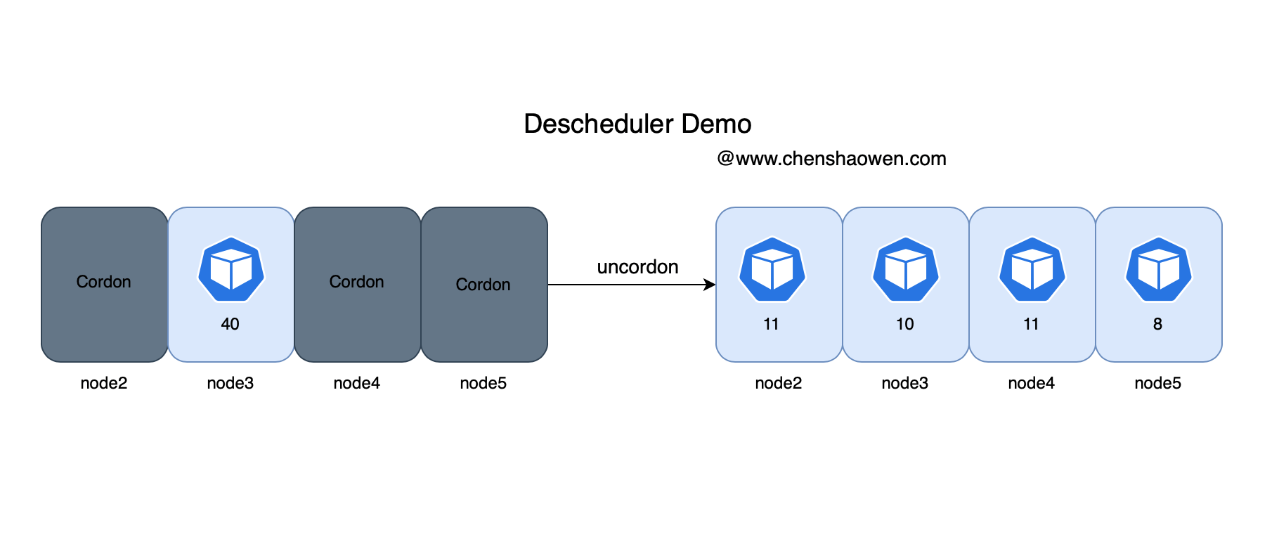
Descscheduler secondary scheduling makes kubernetes load more balanced
"I was laid off by a big factory"
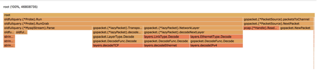
A journey of database full SQL analysis and audit system performance optimization

2022R2移动式压力容器充装试题模拟考试平台操作

Summary of software testing tools in 2021 - unit testing tools

初中学历,从不到3K,到月薪30K+,不设限的人生有多精彩
随机推荐
[data clustering] data set, visualization and precautions are involved in this column
5 lines of code identify various verification codes
Curry carries the fourth game of the warriors against the Celtics
Embedded gd32 code read protection
【图像去噪】基于高斯滤波、均值滤波、中值滤波、双边滤波四种滤波实现椒盐噪声图像去噪附matlab代码
libprint2
When SQL server2019 is installed, the next step cannot be performed. How to solve this problem?
Why must coordinate transformations consist of publishers / subscribers of coordinate transformation information?
最近面了15个人,发现这个测试基础题都答不上来...
【数据聚类】本专栏中涉及数据集、可视化及注意事项
Can official account also bring goods?
JDE 对象管理工作平台介绍及 From 的使用
Jackson XML is directly converted to JSON without writing entity classes manually
Construction of running water lamp experiment with simulation software proteus
lambda 函数完美使用指南
I met 15 people recently and found that I couldn't answer the basic question of this test
The most understandable explanation of coordinate transformation (push to + diagram)
[image detection] SAR image change detection based on depth difference and pcanet with matlab code
Dynamic coordinate transformation in ROS (dynamic parameter adjustment + dynamic coordinate transformation)
Imx6q pwm3 modify duty cycle