当前位置:网站首页>[Verilog advanced challenge of Niuke network question brushing series] ~ multi bit MUX synchronizer
[Verilog advanced challenge of Niuke network question brushing series] ~ multi bit MUX synchronizer
2022-07-07 19:18:00 【AI is very good】
Catalog :
0. Preface
I haven't updated Niu Ke's blog for a few days , I'm busy recently , I can only try to do one watch every day !!! Brush the questions at the same time , Make it small on one side demo, Keep on learning .
Today's problem is mainly a multi bit data transmission across the clock domain , It is also a common question type , It works , How to deal with cross clock domain , You can move to a blog I wrote before , Portal
1. VL48 many bit MUX synchronizer
1.1 Title Description
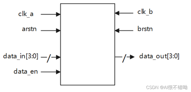
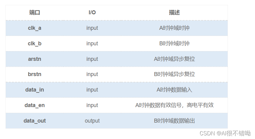
stay data_en For the high period ,data_in Will remain unchanged ,data_en Keep at least 3 individual B Clock cycle . indicate , When data_en For the high time , Data can be synchronized .
In this question data_in The frequency of data change at the end is very low , The change between two adjacent data , At least at intervals 10 individual B Clock cycle .
1.1.1 Signal schematic diagram
1.1.2 Waveform diagram
nothing
1.1.3 Input description
input                 clk_a    ,
input                 clk_b    ,
input                 arstn    ,
input                brstn   ,
input        [3:0]    data_in    ,
input               data_en
1.1.4 Output description
output reg [3:0] dataout
1.2 Their thinking
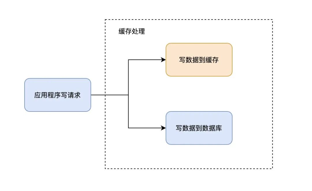
According to the meaning of the topic, the general framework is as follows :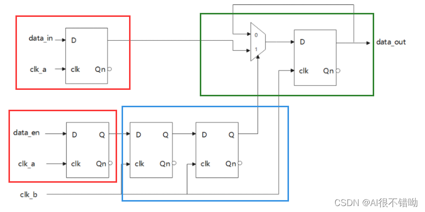
among , The red box indicates data temporary storage as well as Enable temporary storage ; The blue box indicates cross clock domain processing , Use the shape of two beats to complete ; The green box indicates MUX Select and temporarily output the results .
1.3 Code implementation
`timescale 1ns/1ns

module mux(
	input 				clk_a	,
	input 				clk_b	,
	input 				arstn	,
	input				brstn   ,
	input		[3:0]	data_in	,
	input               data_en ,

	output reg  [3:0] 	dataout
);

    // The staging data_en
    reg data_en_reg;
    always @ (posedge clk_a or negedge arstn) begin
        if(!arstn) begin
            data_en_reg <= 1'b0;
        end
        else begin
            data_en_reg <= data_en;
        end
    end

    //data_in
    reg [3:0] data_in_reg;
    always @ (posedge clk_a or negedge arstn) begin
        if(!arstn) begin
            data_in_reg <= 4'd0;
        end
        else begin
            data_in_reg <= data_in;
        end
    end

    // Two beats , Transition across clock domains
    reg data_en_ab1, data_en_ab2;
    always @ (posedge clk_b or negedge brstn) begin
        if(!brstn) begin
            data_en_ab1 <= 1'b0;
            data_en_ab2 <= 1'b0;
        end
        else begin
            data_en_ab1 <= data_en_reg;
            data_en_ab2 <= data_en_ab1;
        end
    end
    // MUX
    always @ (posedge clk_b or negedge brstn) begin
        if(!brstn) begin
            dataout <= 4'd0;
        end
        else begin
            dataout <= data_en_ab2 ? data_in_reg : dataout;
        end
    end
endmodule
1.4 The test file
To be updated ...
1.5 Simulation waveform
To be updated ...
Statement
All my series of articles , Just for learning , Not for commercial use , If there is any infringement , Please inform , To delete !!!
I mainly record the learning process , For myself to review , Then it is to provide reference for future generations , No joy, no spray. !!!
If it's useful to you , Remember to collect + Comment on !!!
边栏推荐
- Mathematical analysis_ Notes_ Chapter 11: Fourier series
- 最长公共前缀(leetcode题14)
- Draw squares with Obama (Lua)
- DeSci:去中心化科学是Web3.0的新趋势?
- 反爬虫的重点:识别爬虫
- [mime notes]
- [information security laws and regulations] review
- In 2021, the national average salary was released. Have you reached the standard?
- 数据验证框架 Apache BVal 再使用
- L1-025 positive integer a+b (Lua)
猜你喜欢
Multimodal point cloud fusion and visual location based on image and laser

Zhong Xuegao wants to remain innocent in the world
數據驗證框架 Apache BVal 再使用
Responsibility chain model - unity
超分辨率技术在实时音视频领域的研究与实践
![Learn open62541 -- [67] add custom enum and display name](/img/98/e5e25af90b3f98c2be11d7d21e5ea6.png)
Learn open62541 -- [67] add custom enum and display name
Do you know all four common cache modes?

博睿数据入选《2022爱分析 · IT运维厂商全景报告》
App capture of charles+drony
2022.07.04
随机推荐
State mode - Unity (finite state machine)
2022.07.02
2022.07.05
App capture of charles+postern
RISCV64
Redis
完整的电商系统
Tips and tricks of image segmentation summarized from 39 Kabul competitions
3.关于cookie
链式二叉树的基本操作(C语言实现)
嵌入式面试题(算法部分)
ES6笔记一
2022.07.02
Number - number (Lua)
Desci: is decentralized science the new trend of Web3.0?
LeetCode1051(C#)
Key points of anti reptile: identifying reptiles
POJ 1182 :食物链(并查集)[通俗易懂]
炒股如何开户?请问一下手机开户股票开户安全吗?
Zhong Xuegao wants to remain innocent in the world