当前位置:网站首页>My notes on intelligent charging pile development (II): overview of system hardware circuit design
My notes on intelligent charging pile development (II): overview of system hardware circuit design
2022-07-03 10:00:00 【Wukong is so timid】
2. My intelligent charging pile Development Notes ( Two ): Overview of system hardware circuit design
2 System hardware circuit design
∗ ∗ ∗ ∗ open discharge whole Ministry hard Pieces of , soft Pieces of set up meter information material , Such as hard Pieces of primary The reason is chart , soft Pieces of Source generation code etc. , see after To continue writing Chapter ∗ ∗ ∗ ∗ \textcolor{red}{**** Open all hardware , Software design data , Such as hardware schematic , Software source code, etc , See following article ****} ∗∗∗∗ open discharge whole Ministry hard Pieces of , soft Pieces of set up meter information material , Such as hard Pieces of primary The reason is chart , soft Pieces of Source generation code etc. , see after To continue writing Chapter ∗∗∗∗

Due to charging control for both , One is TTL UART Interface of the electric control board , One is RS485 Controlled circuit breaker , A choice . By default TTL UART Interface's DCP mode .
4G The data traffic of network module is large , Adopt support DMA Of UART 1 Interface . Dianchuan control board 1, Dianchuan control board 2 And MCU There is also more interactive data , Adopt support DMA Of UART2 UART3 Interface .
Which mode does the power on automatic detection belong to . namely UART2 UART3 All connected to the Dianchuan control board , That is to say, at present TTL UART Interface's DCP mode . here , The debugging serial port in this mode adopts MCU UART4 As DEBUG, The UART Not supported by default DMA receive , Therefore, the UART. otherwise , Use RS485 Charging control of circuit breaker , namely UART2 UART3 Belong to idle UART, Use UART3 As a debug serial port .
    if(dc1_exist == 1 && dc2_exist ==1)
    {
        debug_uart_id = PRINTF_UART_ID_4;
    }
    else
    {

        debug_uart_id = PRINTF_UART_ID_1;
    }
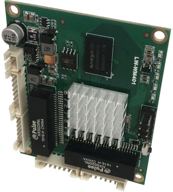
be based on STM32F103VET6 and 4G The hardware structure of the intelligent charging pile of the module is shown in the figure 2 Shown . Gateway control system adopts STM32F103VET6 Microcontrollers and EC20 modular , The microcontroller is based on Cortex-M3 ARM Kernel 32 Bit microprocessor , The microcontroller integrates many modules , Including abundant hardware resources such as memory and communication unit [5]. In addition, the system is also equipped with a charging control board 、DS18B20 Temperature measurement module 、NTC Inter board temperature measurement module 、 Digital tube display module 、PCM Voice file broadcast module 、 Power module .
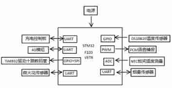
chart 2 System hardware structure
Fig.2 System hardware structure
2.1 Charging control board
STM32F103CET6 The main controller passes 2 road TTL、UART Communicate with the charging control board . The charging control panel uses STM8S105 Control the ten way relay for the controller , The relay adopts JQC-3FF Subminiature high-power relay . The charging control board realizes the intelligent control of the charging socket through the relay , The charging control board will collect charging power and charging power data and transmit them to STM32F103VET6 Main controller . The board is also equipped with AP8022H The chip protects the charging board from overcurrent 、 Over temperature protection and under voltage protection .AP8022H Pulse width modulation controller and 800V High avalanche capability, intelligent power MOSFET.AP8022H The chip also has a built-in high-voltage starting module , Ensure that the system can start quickly .
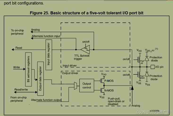
2.1.1 5V–3.3V Level conversion circuit
Dianchuan board is 5V level ,MCU yes 3.3V, Both use UART Communication requires level conversion .

2.1.2 The electric board is connected to the detection circuit
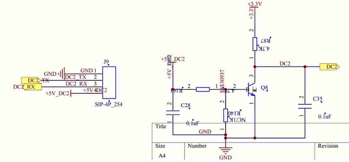
The picture on the left shows that the interfaces of the board are ,GND,TX,RX,5V Power Supply , The corresponding network LABEL yes GND DC2_TX RC2_RX +5V_DC2, Among them +5V_DC2 It is the battery board that produces
When the Dianchuan board is connected MCU Behind the core control board , The reverse circuit of the triode on the right works , here DC2 The level is low
When the electric board is not connected MCU Behind the core control board , The reverse circuit of the triode on the right is not working , here DC2 Pull up the resistor , The level is high
MCU Judge whether there is control board access according to this
2.2 4G Communication module
EC20 It's mobile communications LTE Cat4 All Netcom wireless communication module , collocation SIM Card execution 4G module MQTT Protocol communication , Support maximum downlink rate 150Mbps And maximum uplink rate 50Mbps, Support AT Command operation and FOTA Remote upgrade . System USES STM32F103VET6 Master controller ,EC20 Module and main controller UART2 Connect , With RS485 The protocol realizes the master chip and 4G Data communication between modules .
Here the 4G The reason for the module is to consider our 2G、3G Network services are gradually shutting down , Major operators gradually do not provide 2G、3G Network services , also 4G Communication speed ratio 2G、3G fast , It is more suitable for complex logical business . In order to make the intelligent charging pile operate longer in the future and facilitate remote maintenance , Here the 4G The module is more cost-effective .
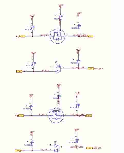
2.2.1 1.8V–3.3V Level conversion circuit
4G Module is 1.8V level ,MCU yes 3.3V, Both use UART Communication requires level conversion .
2.2.2 mobile phone SIM Data communication flow card access circuit

2.2.2 Move far 4G module miniPCIE Interface circuit

2.3 Temperature measurement module
The temperature measurement module is divided into DS18B20 Temperature measurement module and NTC Inter board temperature measurement module .STM32F103VET6 And DS18B20 The temperature measurement module uses 1-Wire Bus protocol for communication , And pass 4.7KΩ The pull-up resistance of is DS18B20 Provide 3.3V voltage . The temperature detection range of the temperature sensor is -55℃ to +125℃, And the temperature range exceeds -10℃ to 85℃ Besides, it also has ±0.5℃ The accuracy of the .DS18B20 The sensor provides 9-Bit To 12-Bit Degree Celsius measurement accuracy ,STM32F103VET6 Main controller and DS18B20 Cooperation can realize the alarm function of triggering the alarm at excessive temperature and low temperature . An alarm causes the main controller control socket to be powered off , It plays a certain role in preventing fire .NTC Inter board temperature measurement module coordination STM32F103VET6 Of ADC_IN9 To achieve , basis NTC Characteristics of thermistor , Convert the collected data into temperature in the main controller , So as to monitor the temperature of the charging board , It is used to prevent the chip from working under abnormal temperature and causing system failure .
DS18B20 The temperature measurement module is mainly used for the environmental temperature measurement of the charging station , Cooperate with smoke sensor and micro spark sensor to send voice alarm after detecting abnormal environmental conditions .
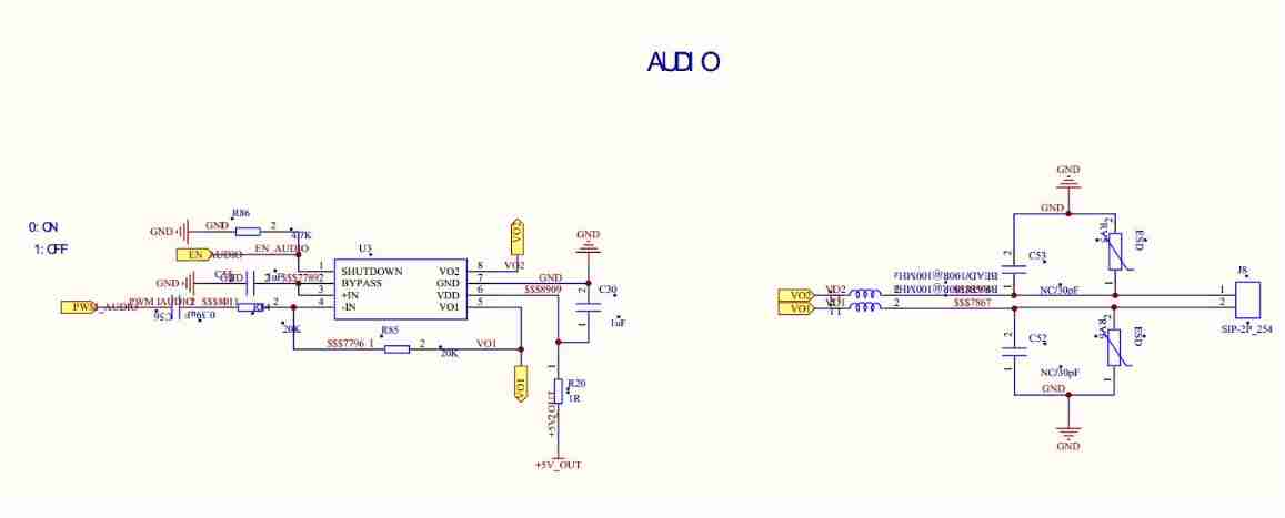
2.4 PCM Voice file broadcast module
STM43F103VET6 built-in 3 A synchronous standard timer . Each timer has a 16 Bit counter 、 One 16 Bit prescaler and 4 Independent PWM passageway . and PCM Voice file usage 16kHz Sampling frequency of ,8BIT Quantization coding of , Its broadcast module only needs one way PWM Channels and 1 A timer can complete the voice broadcast function . When there is PCM When voice files need to be broadcast , With 16kHz Play data at a rate , Data into PWM Duty cycle to control the audio signal , Through the output of filter circuit and audio power amplifier, it is amplified and output to speakers for audio playback [6].
The content of voice broadcast mainly includes charging status broadcast , Such as “X(1-10) Charging started on the th ”、“X(1-10) The charging is completed ” etc. , Let users hear the broadcast content and understand the status of the socket . In case of accidents such as socket fire , Voice broadcast can give an alarm at the first time to remind people to pay attention to safety and control the situation .
2.5 Digital tube display module
STM32F103VET6 The main controller passes GPIO and SPI Two ways TA6932 Chip to control . Between the main controller and the nixie tube module 8 Root line , among 2 The root is power line and ground wire , rest 6 Root and master controller SPI3_SCK、SPI3_MOSI、PD3、PD4、PD5、PD6 Connect .TA6932 The chip receives the data of the main controller through the serial interface, and then checks each LED Drive , Each chip drives 5 road LED Display .
The nixie tube module mainly displays the remaining charging time of the corresponding socket ( In minutes ), Users can intuitively see the remaining service time of the socket .
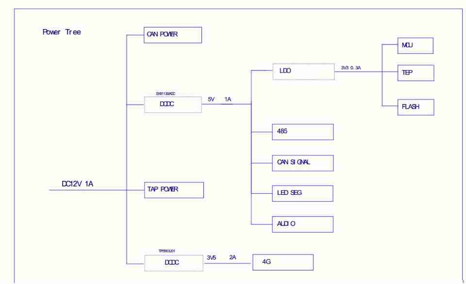
2.6 System power supply Sketch Map
2.7 RS485 Circuit breaker module

边栏推荐
- Simple use of MySQL (addition, deletion, modification and query)
- [CSDN] C1 training problem analysis_ Part IV_ Advanced web
- Uniapp realizes global sharing of wechat applet and custom sharing button style
- PIP references domestic sources
- openEuler kernel 技術分享 - 第1期 - kdump 基本原理、使用及案例介紹
- 新系列单片机还延续了STM32产品家族的低电压和节能两大优势
- (2)接口中新增的方法
- Runtime. getRuntime(). GC () and runtime getRuntime(). The difference between runfinalization()
- Serial communication based on 51 single chip microcomputer
- 01 business structure of imitation station B project
猜你喜欢
要选择那种语言为单片机编写程序呢
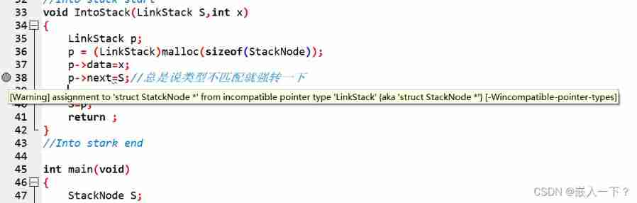
Assignment to '*' form incompatible pointer type 'linkstack' {aka '*'} problem solving

Uniapp realizes global sharing of wechat applet and custom sharing button style
Of course, the most widely used 8-bit single chip microcomputer is also the single chip microcomputer that beginners are most easy to learn
Gpiof6, 7, 8 configuration

Not many people can finally bring their interests to college graduation

03 FastJson 解决循环引用
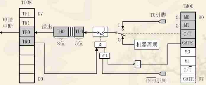
Timer and counter of 51 single chip microcomputer
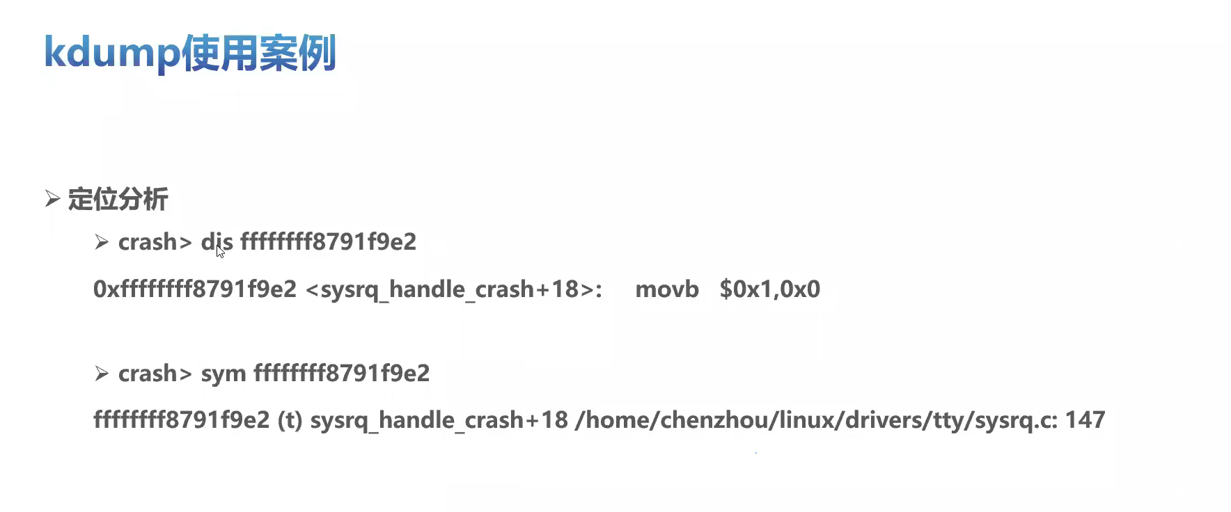
Openeuler kernel technology sharing - Issue 1 - kdump basic principle, use and case introduction

嵌入式系统没有特别明确的定义
随机推荐
03 FastJson 解决循环引用
(1) 什么是Lambda表达式
在三线城市、在县城,很难毕业就拿到10K
CEF下载,编译工程
新系列单片机还延续了STM32产品家族的低电压和节能两大优势
You need to use MySQL in the opening experiment. How can you forget the basic select statement? Remedy is coming~
[male nanny style] teach you to open the first wechat applet
IDEA远程断点调试jar包项目
It is difficult to quantify the extent to which a single-chip computer can find a job
ADS simulation design of class AB RF power amplifier
2020-08-23
端午节快乐!—— canvas写的粽子~~~~~
Design of charging pile mqtt transplantation based on 4G EC20 module
Simple use of MySQL (addition, deletion, modification and query)
Working mode of 80C51 Serial Port
UCI and data multiplexing are transmitted on Pusch (Part 4) --small block lengths
Notes on C language learning of migrant workers majoring in electronic information engineering
Hal library sets STM32 clock
2020-08-23
Schematic diagram and connection method of six pin self-locking switch