当前位置:网站首页>input_ delay
input_ delay
2022-07-07 03:12:00 【qq_ thirty-two million seven hundred and fifty-two thousand eig】
0 Preface
Fundamentals of time series analysis , The underlying principle :
The timing should meet latch Of setup&hold Time . The data cannot change within the required stable window .
Basic timing model
Stack(setup)= T-Tsu-Tco-Tdata adjacent 2 A clock
Stack(hold )= Tco + Tdata - Thd Same as 1 A clock
If Tco and Tdata The delay gets bigger , Retention time Stack (hold) More margin
When there is a hold Violation , Can increase Tdata Routing length to eliminate .
If Tco and Tdata The delay gets bigger , Set up time Stack (setup) The less margin
1 input delay analysis
FPGA Pin From the perspective of 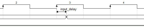
input delay Describe the data port stay latch Look at the edge of the clock , How long did it take for the data to stabilize .
max_delay( analysis setup)
min_delay( analysis hold )
1.1 input delay The classification of
System synchronization is divided into 3 Kind of :(SDR Rising edge 、SDR Falling edge 、DDR)x( Edge alignment )
Source synchronization is divided into 6 Kind of :(SDR Rising edge 、SDR Falling edge 、DDR)x( Center alignment 、 Edge alignment )
External devices may provide Tco\setup\hold\shew
Hidden points needing attention :
- The source synchronization edge alignment is on the receiving side by default (FPGA) In memory PLL Phase shift 180 degree .
- System synchronization only has edge alignment , No center alignment .
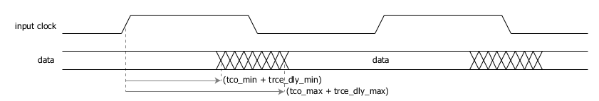
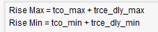
1.2 Tdly The definition of
It's going on intput delay The delay of clock path and data path should be considered when calculating ,
and FPGA Look at , You only need to know the delay of the data relative to the clock , Then the clock delay can be regarded as 0,
And the clock path delay is compensated to the data path delay to get Tdly,Tdly= Data path - Clock path . This can reduce the variables of analysis .
1.3 summary
- Rising edge does not add -clock_fall , The default is the rising edge . The difference between the falling edge and the rising edge is to add -clock_fall .
- DDR There are more constraints -clock_fall -add_delay
- It describes the coordinate time , The second part is the absolute difference . With latch by 0 moment .
2 The specific content
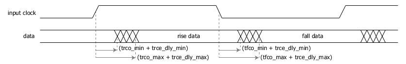
2.1 System synchronization
The data synchronized by the system appears in launch Along the back ,latch Is the next edge
2.1.1 SDR Rising edge
It is known that :
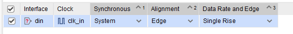
Clock name : clk_in
data port : din
T =10ns
Tco =1~2ns
Tdly=0.3~0.4ns
obtain :
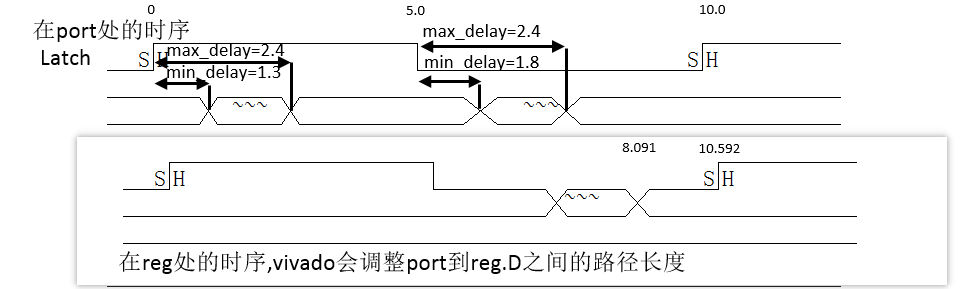
set_input_delay -clock clk_in -max 2.4 [get_ports din]
set_input_delay -clock clk_in -min 1.3 [get_ports din]
It's important to note that -max 2.4 instead of -max_delay 2.4
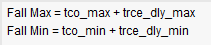
2.1.2 SDR Falling edge
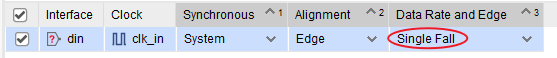
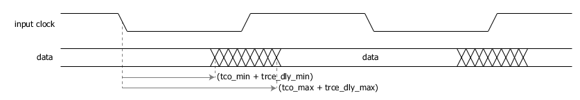
 It is known that :
 Clock name    : clk_in
 data port : din
T   =10ns
Tco =1.5~2ns
Tdly=0.3~0.4ns
 obtain :
set_input_delay  -clock clk_in  -max 2.4  [get_ports  din] -clock_fall
set_input_delay  -clock clk_in  -min 1.8  [get_ports  din] -clock_fall
2.1.2 DDR
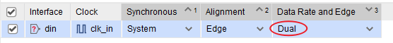
It is known that :
Clock name : clk_in
data port : din
T =10ns
Tco =1.0~2ns Rising edge
Tco =1.5~2ns Falling edge
Tdly=0.3~0.4ns
obtain :
set_input_delay -clock clk_in -max 2.4 [get_ports din]
set_input_delay -clock clk_in -min 1.3 [get_ports din]
set_input_delay -clock clk_in -max 2.4 [get_ports din] -clock_fall -add_delay
set_input_delay -clock clk_in -min 1.8 [get_ports din] -clock_fall -add_delay
// There is a point of knowledge : The data initiated by the falling edge is sampled on the next rising edge . therefore data path It's from 5 Start .
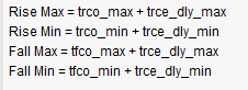
2.2 Source synchronization
2.2.1 Source synchronization Center alignment
Center aligned latch Edge is the next rising edge of the rising edge in the figure . You can see input_delay The range is [dv_are,T-dv_bre], Because the clock is periodic .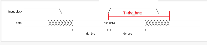
2.2.1.1 Rising edge
set_input_delay -clock [get_clocks clk_in] -min -add_delay 1.0 [get_ports din]
set_input_delay -clock [get_clocks clk_in] -max -add_delay 9.0 [get_ports din]
2.2.1.2 Falling edge
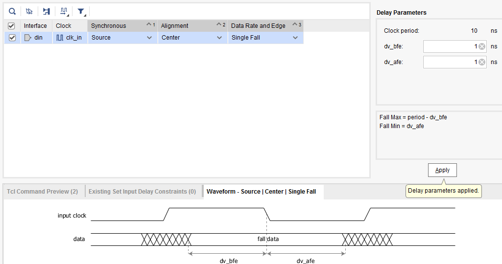
set_input_delay -clock [get_clocks clk_in] -clock_fall -min -add_delay 1.0 [get_ports din]
set_input_delay -clock [get_clocks clk_in] -clock_fall -max -add_delay 9.0 [get_ports din]
2.2.1.3 DDR
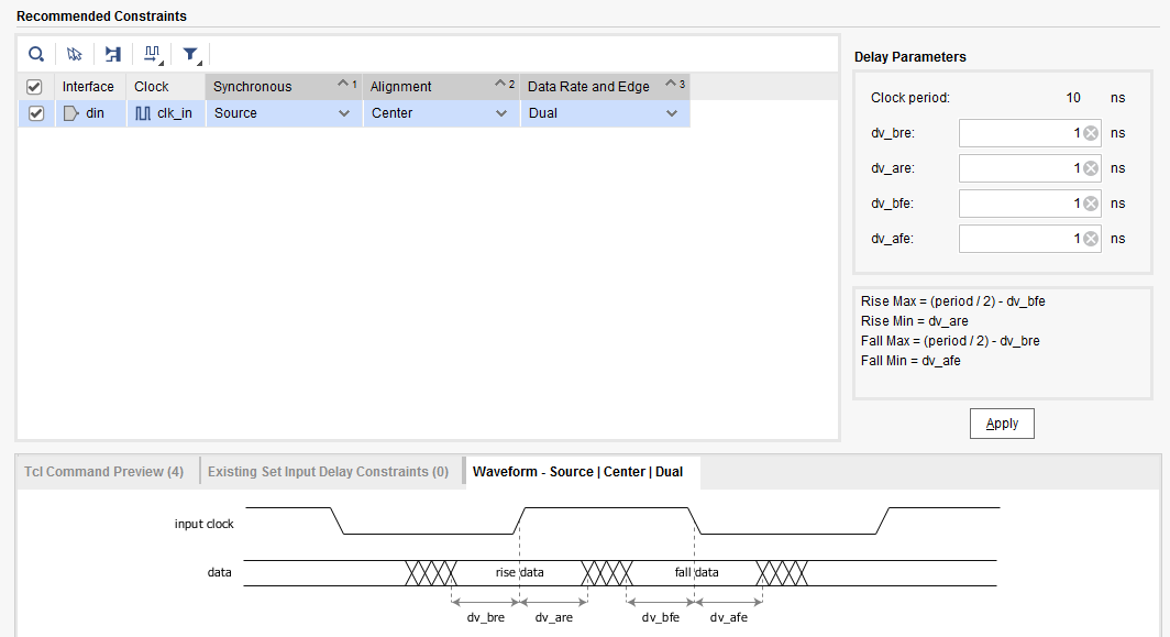
set_input_delay -clock [get_clocks clk_in] -clock_fall -min -add_delay 1.0 [get_ports din]
set_input_delay -clock [get_clocks clk_in] -clock_fall -max -add_delay 4.0 [get_ports din]
set_input_delay -clock [get_clocks clk_in] -min -add_delay 1.0 [get_ports din]
set_input_delay -clock [get_clocks clk_in] -max -add_delay 4.0 [get_ports din]
2.3.2 Source synchronization edge MMCM alignment
MMCM It has the function of adjusting clock phase .latch Edge is the rising edge in the figure ,ltach The data of is the data after the rising edge .
2.3.2.1 Rising edge
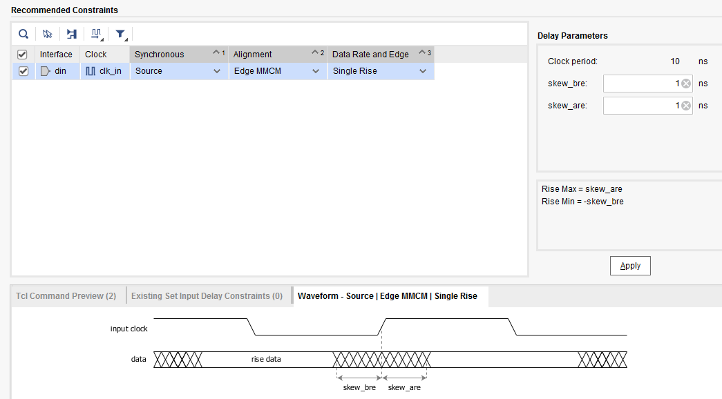
set_input_delay -clock [get_clocks clk_in] -min -add_delay -1.0 [get_ports din]
set_input_delay -clock [get_clocks clk_in] -max -add_delay 1.0 [get_ports din]
2.3.2.2 Falling edge
-clock_fall
2.3.2.3 DDR
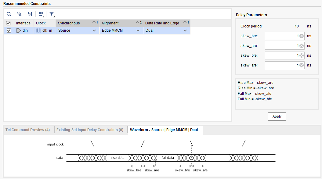
set_input_delay -clock [get_clocks clk_in] -clock_fall -min -add_delay -1.0 [get_ports din]
set_input_delay -clock [get_clocks clk_in] -clock_fall -max -add_delay 1.0 [get_ports din]
set_input_delay -clock [get_clocks clk_in] -min -add_delay -1.0 [get_ports din]
set_input_delay -clock [get_clocks clk_in] -max -add_delay 1.0 [get_ports din]
2.3.3 Source synchronization Align the edges directly
2.3.3.1 Rising edge
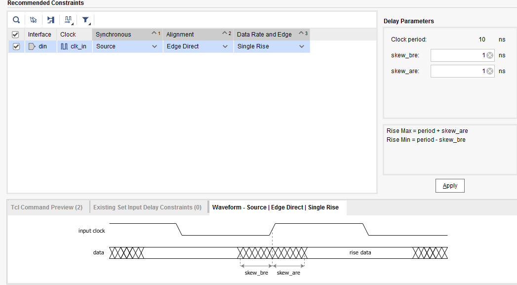
set_input_delay -clock [get_clocks clk_in] -min -add_delay 9.0 [get_ports din]
set_input_delay -clock [get_clocks clk_in] -max -add_delay 11.0 [get_ports din]
2.3.3.2 Falling edge
-fall_clock
2.3.3.3 DDR
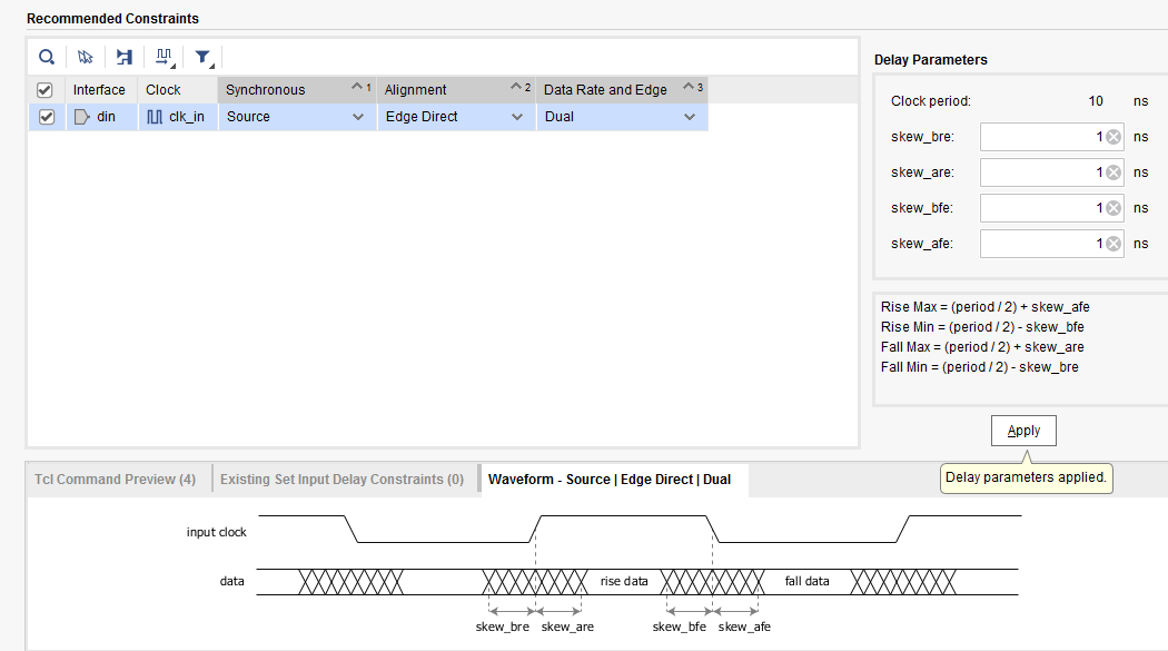
set_input_delay -clock [get_clocks clk_in] -clock_fall -min -add_delay 4.0 [get_ports din]
set_input_delay -clock [get_clocks clk_in] -clock_fall -max -add_delay 6.0 [get_ports din]
set_input_delay -clock [get_clocks clk_in] -min -add_delay 4.0 [get_ports din]
set_input_delay -clock [get_clocks clk_in] -max -add_delay 6.0 [get_ports din]
experiment
Unconstrained input_delay Compiled results of
No constraints added ,slack = infinite , That is, unable to analyze .
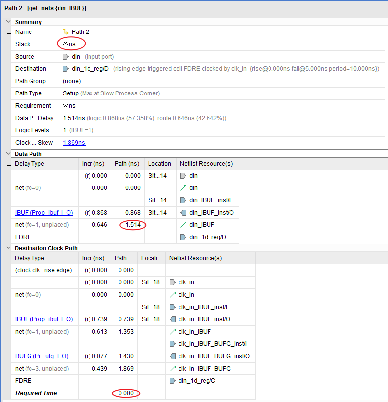
add to DDR input delay constraint
vivado Analyze the worst path ( Rising edge and falling edge hold Can be satisfied ) That is, the falling edge sends data , Rising edge sampling .
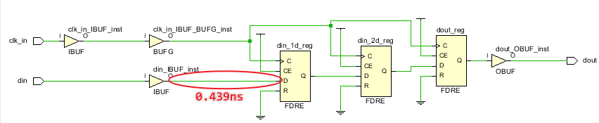
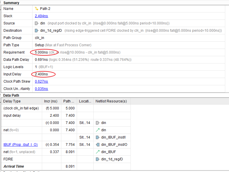
data path The starting point of the launch Along is 5.0ns It indicates that the data analyzed is the data initiated by the falling edge . entered 3.091ns arrive reg.D
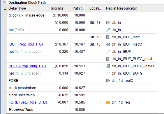
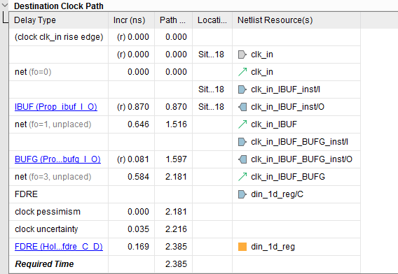
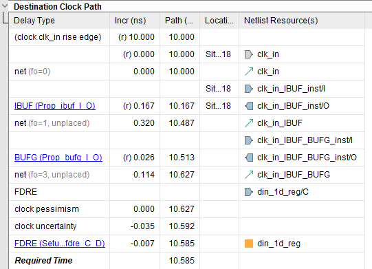
from destination clock path The window sees ,latch Along is 10.0ns, Just in line with the falling edge to send data , Rising edge sampling .
Clock from clk_in port after bufg Wait for the delay , subtracting setup You can get required time. You can see setup It's very small. It's just 0.007ns.
contrast
use MMCM edge Source synchronization
set_input_delay -clock [get_clocks clk_in] -min -add_delay -1.0 [get_ports din]
set_input_delay -clock [get_clocks clk_in] -max -add_delay 1.0 [get_ports din]
direct edge Source synchronization
set_input_delay -clock [get_clocks clk_in] -min -add_delay 9.0 [get_ports din]
set_input_delay -clock [get_clocks clk_in] -max -add_delay 11.0 [get_ports din]
What's the difference between the two ? It feels like there is a cycle difference .
Use the following constraints , Don't add MMCM Will report a mistake hold See the screenshot below , See that the clock path is too long
set_input_delay -clock [get_clocks clk_in] -min -add_delay -1.0 [get_ports din]
set_input_delay -clock [get_clocks clk_in] -max -add_delay 1.0 [get_ports din]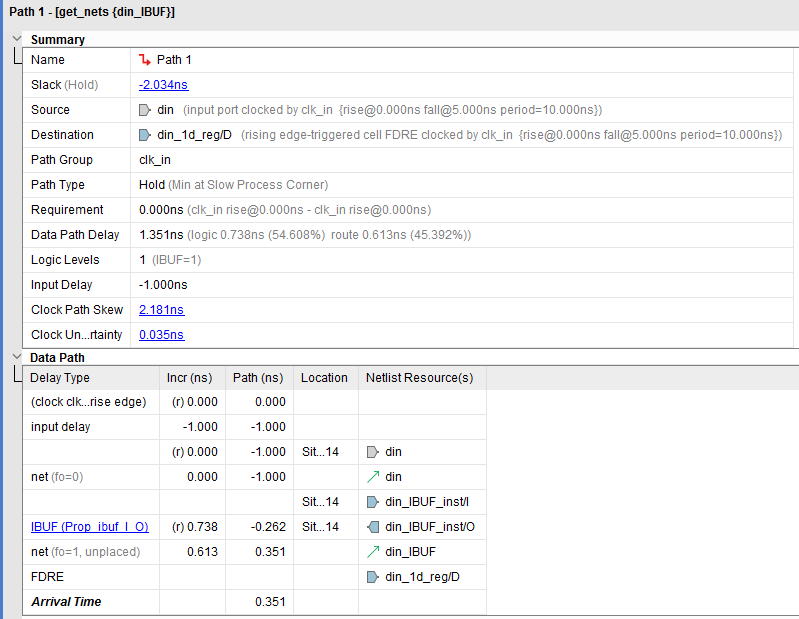
When using the following constraints , Yes setup Report errors
set_input_delay -clock [get_clocks clk_in] -min -add_delay 9.0 [get_ports din]
set_input_delay -clock [get_clocks clk_in] -max -add_delay 11.0 [get_ports din]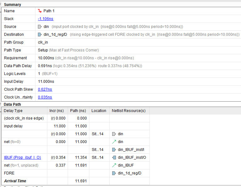
contrast
##  constraint 1:
set_input_delay -clock [get_clocks clk_in] -min -add_delay -1.0 [get_ports din]
set_input_delay -clock [get_clocks clk_in] -max -add_delay  1.0 [get_ports din]
##  constraint 2:
set_input_delay -clock [get_clocks clk_in] -min -add_delay  9.0 [get_ports din]
set_input_delay -clock [get_clocks clk_in] -max -add_delay  11.0 [get_ports din]
constraint 1 And constraints 2 Compare , What's the difference between the two ? It feels like there is a cycle difference 10ns.
Conclusion :
Use constraints 1,vivado Default latch The clock along is 0ns Of , The clock path is from 0ns Start accumulation . At present launch Is the current latch,
Use constraints 2,vivado Default latch The clock along is 10ns Of , The clock path is from 10ns Start accumulation .
Of the two latch The clock differs by one cycle T=10ns.
Reference resources
https://my.oschina.net/msxbo/blog/3122304
边栏推荐
猜你喜欢
杰理之在非蓝牙模式下,手机连接蓝牙不要跳回蓝牙模式处理方法【篇】
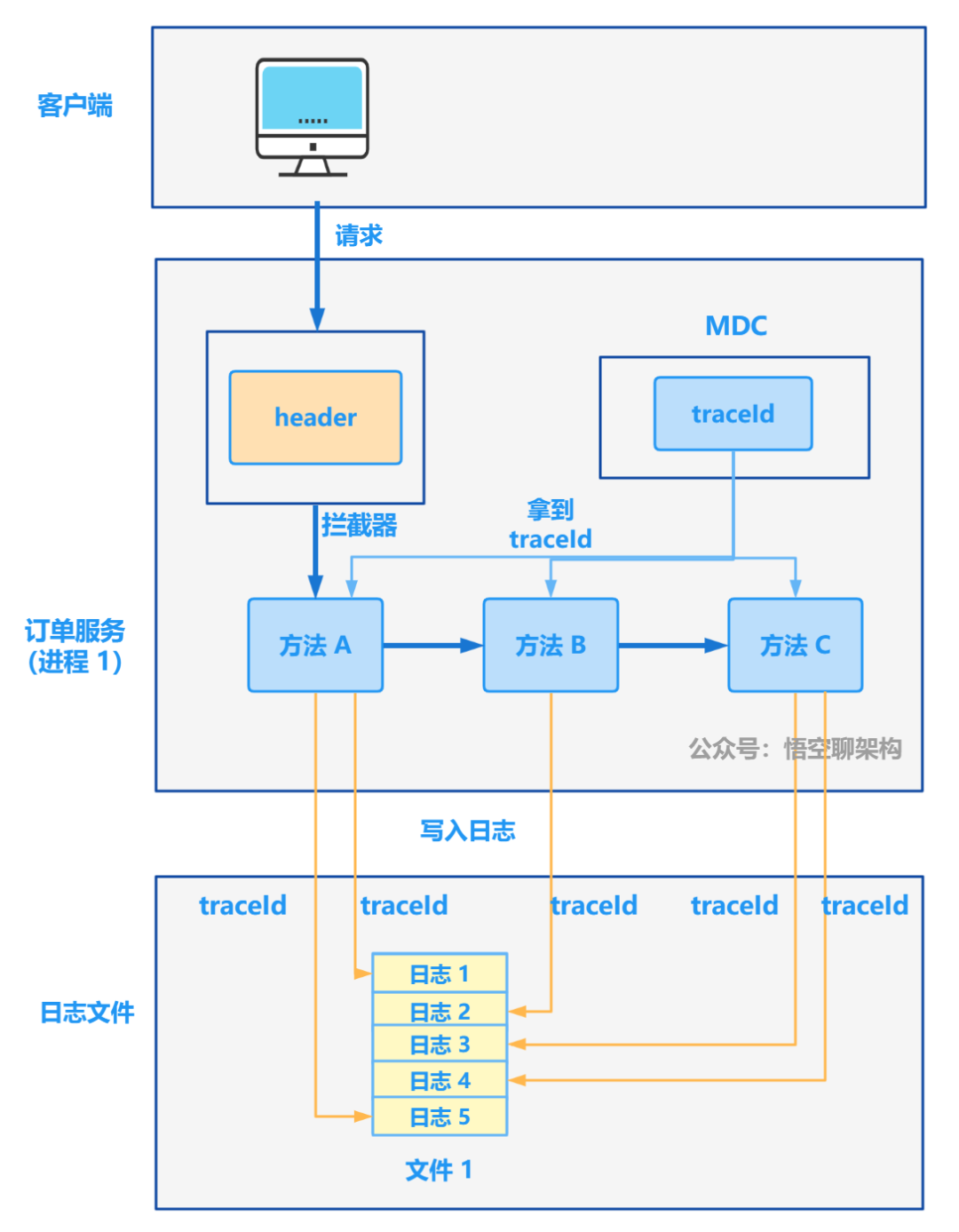
从 1.5 开始搭建一个微服务框架——日志追踪 traceId
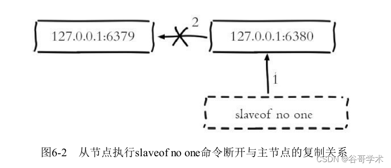
Redis入门完整教程:复制配置

Change your posture to do operation and maintenance! GOPs 2022 Shenzhen station highlights first!
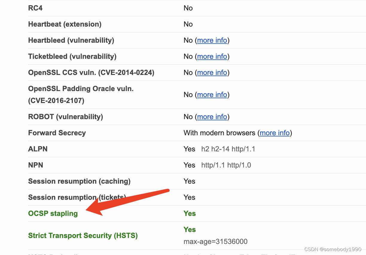
Cryptography series: detailed explanation of online certificate status protocol OCSP
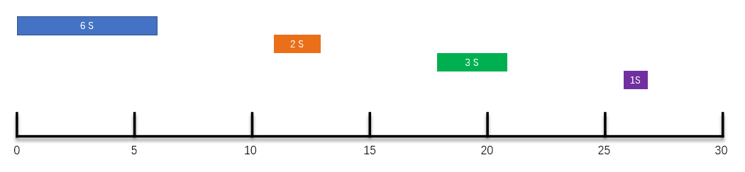
上个厕所的功夫,就把定时任务的三种调度策略说得明明白白
密码学系列之:在线证书状态协议OCSP详解
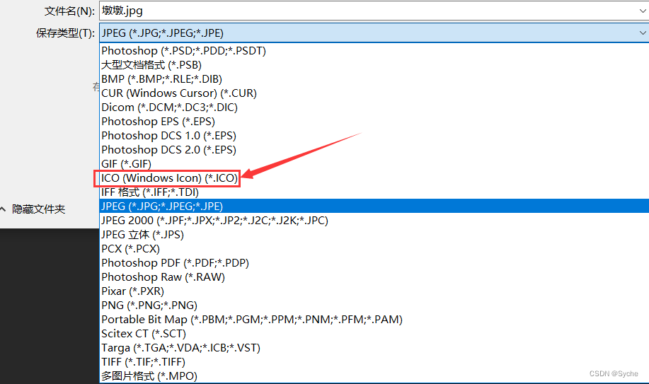
制作(转换)ico图标
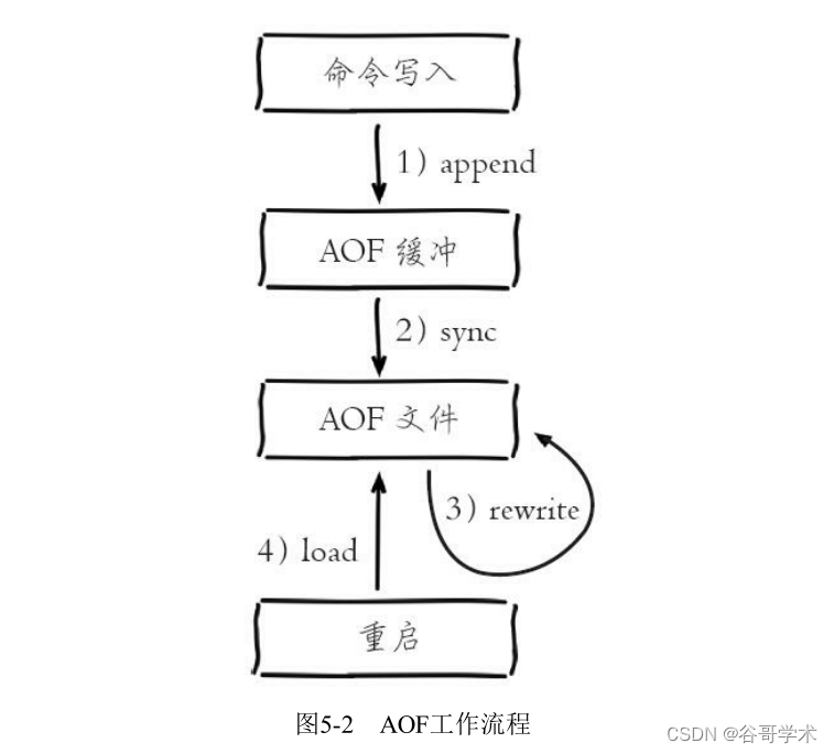
Redis入门完整教程:AOF持久化
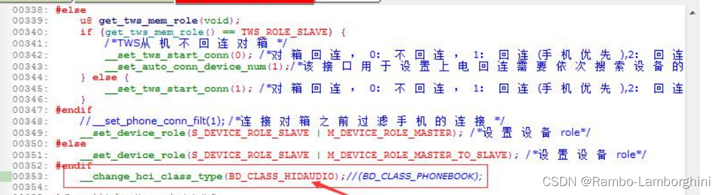
杰理之开启经典蓝牙 HID 手机的显示图标为键盘设置【篇】
随机推荐
oracle连接池长时间不使用连接失效问题
Household appliance industry under the "retail is king": what is the industry consensus?
Detailed explanation of 19 dimensional integrated navigation module sinsgps in psins (time synchronization part)
c语言(字符串)如何把字符串中某个指定的字符删除?
Examples of how to use dates in Oracle
Detailed explanation of 19 dimensional integrated navigation module sinsgps in psins (filtering part)
The version control of 2021 version is missing. Handling method
Redis getting started complete tutorial: client management
杰理之发射端在接收端关机之后假死机【篇】
CVPR 2022 最佳论文候选 | PIP: 6个惯性传感器实现全身动捕和受力估计
ERROR: Could not find a version that satisfies the requirement xxxxx (from versions: none)解决办法
Utilisation de la promesse dans es6
【无标题】
Data analysis from the perspective of control theory
The 8 element positioning methods of selenium that you have to know are simple and practical
SSL证书错误怎么办?浏览器常见SSL证书报错解决办法
Starting from 1.5, build a micro Service Framework -- log tracking traceid
Cryptography series: detailed explanation of online certificate status protocol OCSP
[cpk-ra6m4 development board environment construction based on RT thread studio]
商城商品的知识图谱构建