当前位置:网站首页>Stm32f103c8t6 PWM drive steering gear (sg90)
Stm32f103c8t6 PWM drive steering gear (sg90)
2022-07-07 15:06:00 【Related to the sun_】
Little knowledge : Same timer , Different channel outputs different outputs PWM Characteristics .
For different channel outputs of the same timer PWM, Because they share a counter , therefore frequency It has to be the same , and Duty cycle By their own CCR decision , It can be set separately . also , phase Due to counter update , all PWM Will jump at the same time , So the phase is synchronous .
If you use 1 A timer controls multiple steering gears or DC motors , Use different channels of the same timer PWM, That's fine .
	TIM_OC1Init(TIM2,&TIM_OCInitStructure);
	TIM_OC2Init(TIM2,&TIM_OCInitStructure);
	TIM_OC3Init(TIM2,&TIM_OCInitStructure);
	TIM_OC4Init(TIM2,&TIM_OCInitStructure);
Code :
PWM.h
#ifndef __PWM_H
#define __PWM_H

void PWM_Init();
void PWM_SetCompare2(uint16_t Compare);

#endif
PWM.c
#include "stm32f10x.h" // Device header

void PWM_Init()
{

	RCC_APB1PeriphClockCmd(RCC_APB1Periph_TIM2,ENABLE);  // Turn on timer 2
	RCC_APB2PeriphClockCmd(RCC_APB2Periph_GPIOA,ENABLE);// passageway 2 Clock enable function


	GPIO_InitTypeDef GPIO_InitStructure; 				// Definition GPIO Initializing structure variables
	GPIO_InitStructure.GPIO_Mode = GPIO_Mode_AF_PP;	// Set up GPIO For push-pull output mode
	GPIO_InitStructure.GPIO_Pin = GPIO_Pin_1;
	GPIO_InitStructure.GPIO_Speed = GPIO_Speed_50MHz;	// The speed is set to  50MHz
	GPIO_Init(GPIOA, &GPIO_InitStructure);				// Proceed according to the above parameters  GPIO The initialization

	TIM_InternalClockConfig(TIM2);//TIM The time base unit of is controlled by the internal clock

	TIM_TimeBaseInitTypeDef TIM_TimeBaseInitStructure;
	TIM_TimeBaseInitStructure.TIM_ClockDivision = TIM_CKD_DIV1;
	TIM_TimeBaseInitStructure.TIM_CounterMode = TIM_CounterMode_Up;
	TIM_TimeBaseInitStructure.TIM_Period = 20000 - 1; //ARR  The value of the automatic reloader
	TIM_TimeBaseInitStructure.TIM_Prescaler = 72 - 1; //PSC  Prescaler value   Yes 72M(720000000) Conduct  7200 frequency division   namely 10K At different frequencies   meter 10000 Number  1s Time for
	TIM_TimeBaseInitStructure.TIM_RepetitionCounter = 0;// Repeat counter value
	TIM_TimeBaseInit(TIM2,&TIM_TimeBaseInitStructure);

	TIM_OCInitTypeDef TIM_OCInitStructure;
	TIM_OCStructInit(&TIM_OCInitStructure);
	TIM_OCInitStructure.TIM_OCMode = TIM_OCMode_PWM1;
	TIM_OCInitStructure.TIM_OCPolarity = TIM_OCPolarity_High;// Output polarity selection
	TIM_OCInitStructure.TIM_OutputState = TIM_OutputState_Enable;// Output status enable
	TIM_OCInitStructure.TIM_Pulse = 0;//CCR, That is, the duty cycle is  10%
	TIM_OC2Init(TIM2,&TIM_OCInitStructure);

	TIM_Cmd(TIM2,ENABLE);
}


void PWM_SetCompare2(uint16_t Compare)
{

	TIM_SetCompare2(TIM2, Compare);
}
Serco.h
#ifndef __Servo_H
#define __Servo_H

void Servo_Init(void);
void Servo_SetAngle(float Angle);

#endif
Servo.c
#include "stm32f10x.h" // Device header
#include "PWM.H"

void Servo_Init(void)
{

	PWM_Init();
}

void Servo_SetAngle(float Angle)
{

	PWM_SetCompare2(Angle / 180 * 2000 +500);
}
main.c
#include "stm32f10x.h" // Device header
#include "Delay.h"
#include "LED.h"
#include "Key.h"
#include "OLED.H"
#include "Servo.H"

uint8_t KeyNum;
float Angle; // Steering angle

int main(void)
{

	OLED_Init();
	Servo_Init();
	Key_Init();

	OLED_ShowString(1,1,"Angle:");

	while (1)
	{


		KeyNum = Key_GetNum();
		if(KeyNum == 1)
		{

			Angle +=30;
			if(Angle > 180)
			{

				Angle = 0;
			}
		}
		Servo_SetAngle(Angle);
		OLED_ShowNum(1,7,Angle,3);// Show the angle on the screen

	}
}
What happened :
Changed a steering gear , Then use the oscilloscope to measure that the pin is
WaveOf , But the steering gear isImmobility. Later it was found thatvoltageNot enough .
Work hard , Grow slowly
边栏推荐
- "July 2022" Wukong editor update record
- Niuke real problem programming - day13
- Computer win7 system desktop icon is too large, how to turn it down
- [机缘参悟-40]:方向、规则、选择、努力、公平、认知、能力、行动,读3GPP 6G白皮书的五层感悟
- Zhiting doesn't use home assistant to connect Xiaomi smart home to homekit
- How does the database perform dynamic custom sorting?
- Shengteng experience officer Episode 5 notes I
- 用于增强压缩视频质量的可变形卷积密集网络
- 【跟着江科大学Stm32】STM32F103C8T6_PWM控制直流电机_代码
- 防火墙基础之服务器区的防护策略
猜你喜欢
Notes HCIA
Pandora IOT development board learning (HAL Library) - Experiment 12 RTC real-time clock experiment (learning notes)

什麼是數據泄露

TypeScript 发布 4.8 beta 版本
安恒堡垒机如何启用Radius双因素/双因子(2FA)身份认证
【深度学习】语义分割实验:Unet网络/MSRC2数据集
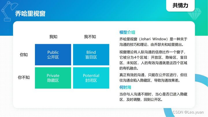
With 8 modules and 40 thinking models, you can break the shackles of thinking and meet the thinking needs of different stages and scenes of your work. Collect it quickly and learn it slowly

JSON解析实例(Qt含源码)
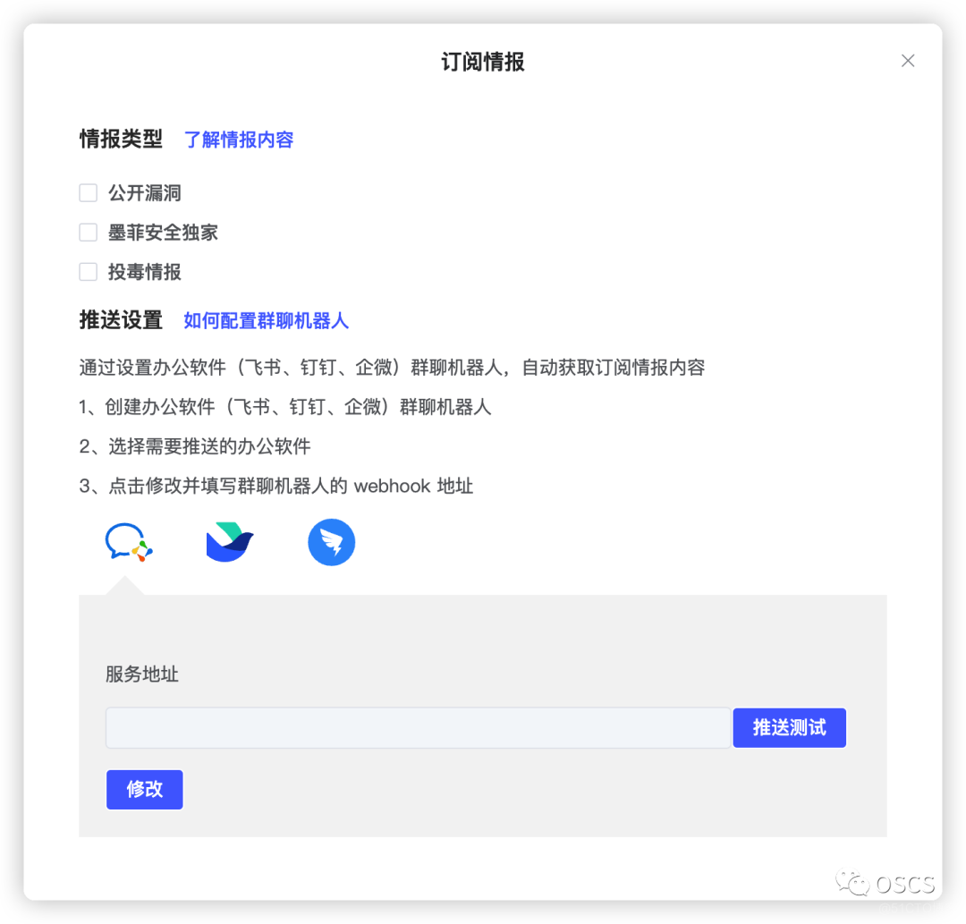
Apache multiple component vulnerability disclosure (cve-2022-32533/cve-2022-33980/cve-2021-37839)

Niuke real problem programming - day13
随机推荐
一文读懂数仓中的pg_stat
【深度学习】语义分割实验:Unet网络/MSRC2数据集
A need to review all the knowledge, H5 form is blocked by the keyboard, event agent, event delegation
Cocoscreator operates spine for animation fusion
Lidar knowledge drops
拜拜了,大厂!今天我就要去厂里
Niuke real problem programming - day13
13 ux/ui/ue best creative inspiration websites in 2022
Ctfshow, information collection: web10
Webrtc audio anti weak network technology (Part 1)
[today in history] July 7: release of C; Chrome OS came out; "Legend of swordsman" issued
Ctfshow, information collection: web6
Guangzhou Development Zone enables geographical indication products to help rural revitalization
Wechat applet - Advanced chapter component packaging - Implementation of icon component (I)
Protection strategy of server area based on Firewall
Ctfshow, information collection: web5
Yyds dry goods inventory # solve the real problem of famous enterprises: cross line
Mathematical modeling -- what is mathematical modeling
简述keepalived工作原理
CPU与chiplet技术杂谈