当前位置:网站首页>Peripheral driver library development notes 43: GPIO simulation SPI driver
Peripheral driver library development notes 43: GPIO simulation SPI driver
2022-07-07 06:07:00 【foxclever】
SPI Bus is our commonly used serial device interface , Generally, we will adapt to hardware SPI Interface , But sometimes when the hardware port is insufficient , We also hope to use software to simulate SPI Hardware interface , Especially when the requirements are not very high . In this article, we will discuss how to use GPIO And software to simulate SPI communication interface .
1、 Function Overview
SPI Serial peripheral interface , It is a synchronous serial communication interface , Used for serial connection between microprocessor and controller and peripheral expansion chip , It has developed into an industrial standard .
1.1、 The physical layer
SPI The bus is usually used in the physical layer 3 Bus and 1 Slice line selection ,3 The buses are SCK、 MOSI、 MISO, The selection line is NSS, Their functions are described as follows :
NSS( Slave Select), Select the signal line from the device , It is often referred to as a chip selection signal line . stay SPI There is no device address in the protocol , So we need to use NSS Signal line to address , When the host wants to select a slave device , Take this from the device's NSS The signal line is set to low level , The slave device is selected , That is, the selection is valid , Then the host starts to communicate with the selected slave device SPI Communications . therefore SPI Communications to NSS Line set low level as start signal , With NSS The line is pulled up as an end signal .
SCK (Serial Clock), Clock signal line , For communication data synchronization . It is generated by the communication host , Determines the rate of communication , Different devices support different maximum clock frequencies , Such as STM32 Of SPI The maximum clock frequency is fpclk/2, When two devices communicate , Communication rate is limited by low speed equipment .
MOSI (Master Output, Slave Input), Main device output / Input from device pin . The data of the host is output from this signal line , The slave reads the data sent by the host through this signal line , That is, the direction of data on this line is from the host to the slave .
MISO(Master Input,, Slave Output), Master input / Output pin from device . The host reads data from this signal line , The data of the slave is output to the host by this signal line , That is, the direction of data on this line is from the host to the slave .
For the use of SPI Bus for communication , One master can communicate with multiple slaves , Clock and data bus are common , Each slave of the film selection line is independent , The specific connection mode is shown in the figure below :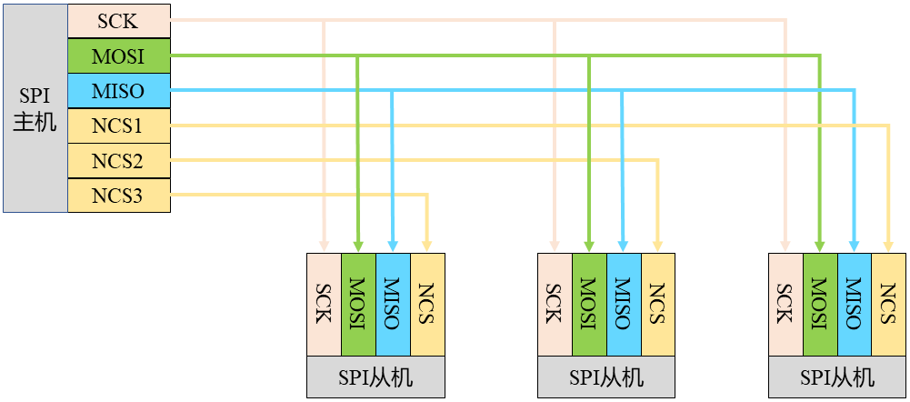
in other words , There are many. SPI From equipment to SPI When the host communicates , Clock line and bus data line of the device SCK、MOSI And MISO Parallel to the same SPI On the bus , That is, no matter how many slaves there are , All use this together 3 A bus . And each slave device has an independent NSS The signal line , How many slave devices are there , There are as many chip selection signal lines .
1.2、 Protocol layer
We have outlined SPI Physical connection mode of bus , Next, let's look at the specific communication protocol . Before understanding the agreement , We need to understand two concepts , The polarity of the real-time clock and the phase of the clock .
The so-called clock polarity , Usually called CPOL, That is, in idle state , The level state of the clock . If SCLK The idle state before and after data transmission is high , So that is CPOL=1; If idle SCLK Is a low level , So that is CPOL=0.
And the phase of the clock , Usually called CPHA, It means that the data sampling is at the... Of the clock pulse 1 The first jump edge is still in the first 2 Jump edge . If in SCK Of the 1 Data sampling is carried out along jump edges , be CPHA=0; If in SCK Of the 2 A jump edge sampling , be CPHA=1.
In the communication protocol , according to CPOL and CPHA Different values exist 4 Different configurations , Different configuration modes correspond to different communication modes .
(1) When CPOL=0,CPHA=0 when , Idle state clock SCK The level of should be kept low , The sampling time of data is at the edge of odd jump of clock pulse , The sequence diagram is as follows :
(2) When CPOL=0,CPHA=1 when , Idle state clock SCK The level of should be kept low , The sampling time of the data is at the even jump edge of the clock pulse , The sequence diagram is as follows :
(3) When CPOL=1,CPHA=0 when , Idle state clock SCK The level of should be kept at high level , The sampling time of data is at the edge of odd jump of clock pulse , The sequence diagram is as follows :
(4) When CPOL=1,CPHA=1 when , Idle state clock SCK The level of should be kept at high level , The sampling time of the data is at the even jump edge of the clock pulse , The sequence diagram is as follows :
According to the clock , take SPI The working mode of the bus is divided into 4 Kind of , As shown in the figure below :
Only when the master and slave have the same working mode , The master and slave computers can communicate normally . in application ,“ Pattern 0” And “ Pattern 3” It is a common working mode , But this should be taken into account in our drive design 4 Patterns , To have wider adaptability .
2、 Drive design and implementation
We have briefly described SPI Physical connection and communication protocol of communication bus , Next, we will design and implement the protocol based on GPIO Simulated SPI Bus driver .
2.1、 Object definitions
We still use the idea of object-based to realize based on GPIO Simulated SPI Bus driver . Since it is based on objects , Then we need to get an object before using it . So we must first define a based on GPIO Simulated SPI The object of the bus .
2.1.1、 Abstraction of objects
We need to get based on GPIO Simulated SPI The object of the bus , We need to analyze its basic characteristics first . Generally speaking , An object contains at least two characteristics of attributes and operations . Next, let's consider from these two aspects based on GPIO Simulated SPI The object of the bus .
Let's first consider the properties of objects , As an attribute, it must be something used to identify or record the characteristics of an object . We have learned before SPI Some features and unique settings of the bus , So can these characteristics and settings become the attributes of the object ?
We consider it as a synchronous bus ,SPI The control of the bus requires a clock , It's about SPI The communication rate of the bus , This communication rate is not only configured SPI The working mode of the bus also identifies the current working state , So we take the working rate as the simulation SPI A property of the bus object . We discussed earlier SPI The working mode of the bus , The working mode consists of CPOL and CPHA decision , Therefore, the working mode will be determined when initializing the bus , So we need records CPOL and CPHA, We will CPOL and CPHA Also as an attribute of the object .
Next, let's consider GPIO simulation SPI Bus operation problems . We will implement those objects , And depending on the specific platform, the behavior implementation is defined as the operation of the object . about GPIO simulation SPI For example , We need to send and receive data through the bus , The implementation of receiving and sending depends on the specific software and hardware platform , So we define sending data and receiving data as object operations .SPI As a synchronous bus, the bus needs a clock , The clock operation also depends on the specific software and hardware platform , So we will always control the operation of objects .
On the basis of the above, we are concerned with GPIO simulation SPI Analysis of bus , We can define GPIO simulation SPI The bus object types are as follows :
/* Definition GPIO simulation SPI Interface object */
typedef struct SimuSPIObject{
  uint16_t CPOL:1;
  uint16_t CPHA:1;
  uint16_t period:14;   // Determine that the speed is greater than 0K Less than or equal to 400K The integer of , The default is 100K
  void (*SetSCKPin)(SimuSPIPinValueType op);        // Set up SCL Pin
  void (*SetMOSIPin)(SimuSPIPinValueType op);        // Set up SDA Pin
  uint8_t (*ReadMISOPin)(void);                  // Read SDA Pin position
  void (*Delayus)(volatile uint32_t period);    // Speed delay function
}SimuSPIObjectType;
2.1.2、 Object initialization
We know , You need to initialize an object before using it , So let's think about it here GPIO simulation SPI Object initialization function . Generally speaking , Initialization functions need to deal with several aspects . One is to check whether the input parameters are reasonable ; The second is to assign initial values to the attributes of objects ; The third is to do the necessary initialization configuration for the object . So we design GPIO simulation SPI The initialization function of the object is as follows :
/* GPIO simulation SPI Communication initialization  */
void SimuSPIInitialization(SimuSPIObjectType *simuSPIInstance,// Initialized simulation SPI object
                           uint32_t speed,      // clock frequency
                           SimuSPICPOLType CPOL,        // Clock polarity
                           SimuSPICPHAType CPHA,        // clock frequency
                           SimuSPISetSCKPin setSCK,     //SCK Clock operation function pointer
                           SimuSPISetMOSIPin setMOSI,   //MOSI Operation function pointer
                           SimuSPIReadMISOPin getMISO,  //MISO Operation function pointer
                           SimuSPIDelayus delayus       // Microsecond delay operation function pointer
                               )
{
    if((simuSPIInstance==NULL)||(setSCK==NULL)||(setMOSI==NULL)||(getMISO==NULL)||(delayus==NULL))
    {
        return;
    }

    simuSPIInstance->SetSCKPin=setSCK;
    simuSPIInstance->SetMOSIPin=setMOSI;
    simuSPIInstance->ReadMISOPin=getMISO;
    simuSPIInstance->Delayus=delayus;

    /* Initialization speed , Default 100K*/
    if((speed>0)&&(speed<=500))
    {
        simuSPIInstance->period=500/speed;
    }
    else
    {
        simuSPIInstance->period=5;
    }

    simuSPIInstance->CPOL=CPOL;
    simuSPIInstance->CPHA=CPHA;

    /* Pull up the bus , Make idle */

    if(simuSPIInstance->CPOL==SimuSPI_POLARITY_LOW)
    {
        simuSPIInstance->SetSCKPin(SimuSPI_Reset);
    }
    else
    {
        simuSPIInstance->SetSCKPin(SimuSPI_Set);
    }
}
2.2、 The object operation
We have defined the object type , It also implements the initialization function of the object , But we haven't implemented the specific operation of the object , So next, let's implement the specific operation of the object .
2.2.1、 Data transmission
When we use SPI To realize data communication , It is inevitable to send data , So when we use GPIO simulation SPI Port, you need to solve the problem of data transmission . Here we consider using simulation SPI The problem of sending a byte , Because sending multiple bytes is nothing more than repeating several times . According to the sequence diagram in different modes analyzed above, we can write GPIO simulation SPI The function to send a byte is as follows :
/*  By simulating SPI Send a byte  */
static void SendByteBySimuSPI(SimuSPIObjectType *simuSPIInstance,uint8_t byte)
{
//    uint8_t length[2]={8,16};

    if(simuSPIInstance->CPOL==SimuSPI_POLARITY_LOW)
    {
        /* Pull it down SCL Pin preparation data transmission */
        simuSPIInstance->SetSCKPin(SimuSPI_Reset);

        if(simuSPIInstance->CPHA==SimuSPI_PHASE_1EDGE)  // Pattern 0
        {
            for(uint8_t count = 0; count < 8; count++)
            {
                if(byte & 0x80)     // Send the highest bit each time
                {
                    simuSPIInstance->SetMOSIPin(SimuSPI_Set);
                }
                else
                {
                    simuSPIInstance->SetMOSIPin(SimuSPI_Reset);
                }
                byte <<= 1;         // After sending a bit , The left one

                simuSPIInstance->Delayus(simuSPIInstance->period);
                simuSPIInstance->SetSCKPin(SimuSPI_Set);
                simuSPIInstance->Delayus(simuSPIInstance->period);
                simuSPIInstance->SetSCKPin(SimuSPI_Reset);
            }
        }
        else    // Pattern 1
        {
            for(uint8_t count = 0; count < 8; count++)
            {
                if(byte & 0x80)     // Send the highest bit each time
                {
                    simuSPIInstance->SetMOSIPin(SimuSPI_Set);
                }
                else
                {
                    simuSPIInstance->SetMOSIPin(SimuSPI_Reset);
                }
                byte <<= 1;         // After sending a bit , The left one

                simuSPIInstance->SetSCKPin(SimuSPI_Set);
                simuSPIInstance->Delayus(simuSPIInstance->period);
                simuSPIInstance->SetSCKPin(SimuSPI_Reset);
                simuSPIInstance->Delayus(simuSPIInstance->period);
            }
        }
    }
    else
    {
        /* Pull it down SCL Pin preparation data transmission */
        simuSPIInstance->SetSCKPin(SimuSPI_Set);

        if(simuSPIInstance->CPHA==SimuSPI_PHASE_1EDGE)  // Pattern 2
        {
            for(uint8_t count = 0; count < 8; count++)
            {
                if(byte & 0x80)     // Send the highest bit each time
                {
                    simuSPIInstance->SetMOSIPin(SimuSPI_Set);
                }
                else
                {
                    simuSPIInstance->SetMOSIPin(SimuSPI_Reset);
                }
                byte <<= 1;         // After sending a bit , The left one

                simuSPIInstance->Delayus(simuSPIInstance->period);
                simuSPIInstance->SetSCKPin(SimuSPI_Reset);
                simuSPIInstance->Delayus(simuSPIInstance->period);
                simuSPIInstance->SetSCKPin(SimuSPI_Set);
            }
        }
        else    // Pattern 3
        {
            for(uint8_t count = 0; count < 8; count++)
            {
                if(byte & 0x80)     // Send the highest bit each time
                {
                    simuSPIInstance->SetMOSIPin(SimuSPI_Set);
                }
                else
                {
                    simuSPIInstance->SetMOSIPin(SimuSPI_Reset);
                }
                byte <<= 1;         // After sending a bit , The left one

                simuSPIInstance->Delayus(simuSPIInstance->period);
                simuSPIInstance->SetSCKPin(SimuSPI_Reset);
                simuSPIInstance->Delayus(simuSPIInstance->period);
                simuSPIInstance->SetSCKPin(SimuSPI_Set);
            }
        }
    }
}
2.2.2、 Data reception
about SPI Ports do not only need to send data , You also need to receive data from the other party , Again, let's consider the case of receiving a byte . Similarly, we face different modes according to the front , The timing of receiving data requires that you can write a function to receive a byte as follows :
/*  By simulating SPI Receive a byte  */
static uint8_t RecieveByteBySimuSPI(SimuSPIObjectType *simuSPIInstance)
{
    uint8_t receive = 0;

    if(simuSPIInstance->CPOL==SimuSPI_POLARITY_LOW)
    {
        /* Pull it down SCL Pin preparation data transmission */
        simuSPIInstance->SetSCKPin(SimuSPI_Reset);

        if(simuSPIInstance->CPHA==SimuSPI_PHASE_1EDGE)  // Pattern 0
        {
            for(uint8_t count = 0; count < 8; count++ )
            {
                simuSPIInstance->SetSCKPin(SimuSPI_Set);
                simuSPIInstance->Delayus(simuSPIInstance->period);

                receive <<= 1;

                if(simuSPIInstance->ReadMISOPin())
                {
                    receive++;
                }
                simuSPIInstance->SetSCKPin(SimuSPI_Reset);
                simuSPIInstance->Delayus(simuSPIInstance->period);
            }
        }
        else    // Pattern 1
        {
            simuSPIInstance->SetSCKPin(SimuSPI_Set);
            simuSPIInstance->Delayus(simuSPIInstance->period);
            for(uint8_t count = 0; count < 8; count++ )
            {
                simuSPIInstance->SetSCKPin(SimuSPI_Reset);
                simuSPIInstance->Delayus(simuSPIInstance->period);

                receive <<= 1;

                if(simuSPIInstance->ReadMISOPin())
                {
                    receive++;
                }
                simuSPIInstance->SetSCKPin(SimuSPI_Set);
                simuSPIInstance->Delayus(simuSPIInstance->period);
            }
            simuSPIInstance->SetSCKPin(SimuSPI_Reset);
        }
    }
    else
    {
        /* Pull it down SCL Pin preparation data transmission */
        simuSPIInstance->SetSCKPin(SimuSPI_Set);

        if(simuSPIInstance->CPHA==SimuSPI_PHASE_1EDGE)  // Pattern 2
        {
            for(uint8_t count = 0; count < 8; count++ )
            {
                simuSPIInstance->SetSCKPin(SimuSPI_Reset);
                simuSPIInstance->Delayus(simuSPIInstance->period);

                receive <<= 1;

                if(simuSPIInstance->ReadMISOPin())
                {
                    receive++;
                }
                simuSPIInstance->SetSCKPin(SimuSPI_Set);
                simuSPIInstance->Delayus(simuSPIInstance->period);
            }
        }
        else    // Pattern 3
        {
            simuSPIInstance->SetSCKPin(SimuSPI_Reset);
            simuSPIInstance->Delayus(simuSPIInstance->period);
            for(uint8_t count = 0; count < 8; count++ )
            {
                simuSPIInstance->SetSCKPin(SimuSPI_Set);
                simuSPIInstance->Delayus(simuSPIInstance->period);

                receive <<= 1;

                if(simuSPIInstance->ReadMISOPin())
                {
                    receive++;
                }
                simuSPIInstance->SetSCKPin(SimuSPI_Reset);
                simuSPIInstance->Delayus(simuSPIInstance->period);
            }
            simuSPIInstance->SetSCKPin(SimuSPI_Set);
        }
    }

    return receive;
}
3、 Use of drivers
We have designed and implemented GPIO simulation SPI Bus driver , Next, we will design a simple use case based on this driver , To verify the correctness of the driver .
3.1、 Declare and initialize objects
We implement based on objects GPIO simulation SPI Driven , So before we start, we need to declare a simulation SPI Object as follows :
SimuSPIObjectType simuSPI;
After declaring this object , We also need to initialize this variable to use . Previously, we have implemented the initialization function of object variables , Using this function, you can easily initialize object variables , This function has multiple inputs :
SimuSPIObjectType *simuSPIInstance,// Initialized simulation SPI object
uint32_t speed,              // clock frequency
SimuSPICPOLType CPOL,        // Clock polarity
SimuSPICPHAType CPHA,        // Clock phase
SimuSPIDataSizeType dataSize,// Data length
SimuSPISetSCKPin setSCK,     //SCK Clock operation function pointer
SimuSPISetMOSIPin setMOSI,   //MOSI Operation function pointer
SimuSPIReadMISOPin getMISO,  //MISO Operation function pointer
SimuSPIDelayus delayus       // Microsecond delay operation function pointer
In these parameters simuSPIInstance Pointer to the object variable we want to initialize . Clock polarity 、 Clock phase and data length are enumerators , We can choose input according to the actual use requirements . The clock frequency is the clock speed we want , Maximum 500K. The remaining parameters are pointers to the callback function . These functions are what we need to implement in the application , Their prototypes are as follows :
// Set up SCL Pin
typedef void (*SimuSPISetSCKPin)(SimuSPIPinValueType op);
// Set up SDA Pin
typedef void (*SimuSPISetMOSIPin)(SimuSPIPinValueType op);
// Read SDA Pin position
typedef uint8_t (*SimuSPIReadMISOPin)(void);
// Speed delay function
typedef void (*SimuSPIDelayus)(volatile uint32_t period);
The implementation of these functions is related to the specific application platform , We are STM32F407 Based on HAL The functions implemented by the library are as follows :
// Set up SCL Pin
void SPISCKOperation(SimuSPIPinValueType op)
{
    GPIO_PinState PinState=(GPIO_PinState)op;

    HAL_GPIO_WritePin(GPIOSPI, SPISCK, PinState);
}

// Set up SDA Pin
void SPIMOSIOperation(SimuSPIPinValueType op)
{
    GPIO_PinState PinState=(GPIO_PinState)op;

    HAL_GPIO_WritePin(GPIOSPI, SPIMOSI, PinState);
}

// Read SDA Pin position
uint8_t SPIMISORead(void)
{
    if(HAL_GPIO_ReadPin(GPIOSPI, SPIMISO))
    {
        return 1;
    }

    return 0;
}
The delay operation function is the one commonly used in our system Delayus. With these parameters, we call the initialization function to initialize the object variables as follows :
/* GPIO simulation SPI Communication initialization  */
    SimuSPIInitialization(&simuSPI,// Initialized simulation SPI object
                          500,              // clock frequency
                          SimuSPI_POLARITY_LOW,        // Clock polarity
                          SimuSPI_PHASE_1EDGE,        // clock frequency
                          SimuSPI_DataSize_8Bit,// Data length
                          SPISCKOperation,     //SCK Clock operation function pointer
                          SPIMOSIOperation,   //MOSI Operation function pointer
                          SPIMISORead,  //MISO Operation function pointer
                          Delayus       // Microsecond delay operation function pointer
                              );
3.2、 Object based operations
After initializing this object variable , We can operate this object based on it . We implement a simple operation of reading and writing data based on driver as follows :
/*  Using simulation SPI Read and write data */
void SimuSPIDataExchange(void)
{
    uint8_t wDatas[3];
    uint8_t rDatas[3];

    /*  By simulating SPI Write data to the slave  */
    WriteDataBySimuSPI(&simuSPI,wDatas,3,1000);

    HAL_Delay(10);

    /*  By simulating SPI Since the station reads data  */
    ReadDataBySimuSPI(&simuSPI,rDatas, 3,1000);

    HAL_Delay(10);

    /*  By simulating SPI Realize the combined operation of writing data first and then reading data for the slave station  */
    WriteReadDataBySimuSPI(&simuSPI, wDatas,3,rDatas, 3,1000);

    HAL_Delay(10);

    /*  By simulating SPI Realize the combined operation of writing and reading data to the slave station at the same time */
    WriteWhileReadDataBySimuSPI(&simuSPI, wDatas,rDatas,3,1000);

}
We tested the read data separately 、 Data distribution 、 Test of writing and reading data at the same time and reading after writing , The effect is quite ideal .
4、 Application Summary
In this article , We design and implement a GPIO Simulated SPI Interface driver . On this basis, a simple test application is designed . We go through GPIO Simulated SPI Interface to SPI Interface Flash Write data in 、 Reading data 、 There is no problem in the test of reading and writing at the same time and writing before reading .
When using the driver, you should pay attention to , Due to the use of GPIO Simulated SPI port , Its speed is limited , At present, it can support up to 500K, No matter how fast it is, it cannot be supported . So this driver can only be used when the communication speed is less than 500K The equipment .
Welcome to your attention :
边栏推荐
- @Detailed differences between pathvariable and @requestparam
- 搞懂fastjson 对泛型的反序列化原理
- cf:C. Column Swapping【排序 + 模拟】
- 成为资深IC设计工程师的十个阶段,现在的你在哪个阶段 ?
- 【FPGA教程案例14】基于vivado核的FIR滤波器设计与实现
- [SQL practice] a SQL statistics of epidemic distribution across the country
- Industrial Finance 3.0: financial technology of "dredging blood vessels"
- Ctfshow-- common posture
- Harmonyos practice - Introduction to development, analysis of atomized services
- C. colonne Swapping [tri + Simulation]
猜你喜欢
SAP Spartacus checkout 流程的扩展(extend)实现介绍

从“跑分神器”到数据平台,鲁大师开启演进之路

POI excel export, one of my template methods
Harmonyos practice - Introduction to development, analysis of atomized services

Red Hat安装内核头文件
深度聚类:将深度表示学习和聚类联合优化

Randomly generate session_ id
Three level menu data implementation, nested three-level menu data
![C. colonne Swapping [tri + Simulation]](/img/0e/64d17980d3ec0051cdfb5fdb34e119.png)
C. colonne Swapping [tri + Simulation]

Say sqlyog deceived me!
随机推荐
[FPGA tutorial case 13] design and implementation of CIC filter based on vivado core
I didn't know it until I graduated -- the principle of HowNet duplication check and examples of weight reduction
R language [logic control] [mathematical operation]
盘点国内有哪些EDA公司?
Ctfshow-- common posture
mac版php装xdebug环境(m1版)
Personal imitation SSM framework
改变ui组件原有样式
PTA 天梯赛练习题集 L2-003 月饼 测试点2,测试点3分析
C note 13
Reading notes of Clickhouse principle analysis and Application Practice (6)
【SQL实战】一条SQL统计全国各地疫情分布情况
Nvisual network visualization
Explication contextuelle du langage Go
Pytorch builds neural network to predict temperature
A freshman's summary of an ordinary student [I don't know whether we are stupid or crazy, but I know to run forward all the way]
DC-7靶机
zabbix_ Get test database failed
Introduction to the extension implementation of SAP Spartacus checkout process
C. colonne Swapping [tri + Simulation]