当前位置:网站首页>Influence of oscilloscope probe on measurement bandwidth
Influence of oscilloscope probe on measurement bandwidth
2022-07-05 20:56:00 【PRBTEK】
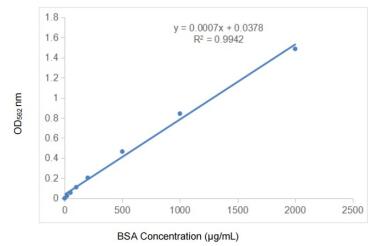
Bandwidth is defined as the measurement system on the amplitude and frequency diagram is lower than the reference level 3dB The point of , Pictured 4.7 Shown , This shows that 3dB Response curve of point .

4.7. Bandwidth is defined as the decrease in amplitude in the response curve -3dB The frequency of
It is necessary to point out , The measuring system has a low amplitude in the rated bandwidth 3dB. This means that you can predict the frequency at the bandwidth limit , Amplitude measurement will have 30% The error of the .
Usually , Users will not use the oscilloscope with the full bandwidth limit . however , If amplitude accuracy is critical , Prepare to reduce the rated bandwidth of the oscilloscope accordingly .
for example , Consider the following figure 4.8 The expansion diagram of bandwidth roll off shown in . The horizontal scale in this figure shows that the result is better than 30% The rating reduction factor required for amplitude accuracy . If there is no rating reduction factor ( The coefficient is 1.0),100MHz Oscilloscope in 100MHz The amplitude error will be as high as 30%. If you want the amplitude measurement to fall on 3% Within the scope of , The bandwidth of this oscilloscope must be 0.3 The coefficient drops to 30MHz. When the frequency exceeds 30MHz when , The amplitude error will exceed 3%.

4.8. Rated bandwidth drop curve
The above example indicates the overall rule of thumb for oscilloscope selection . Yes 3% Amplitude measurement within , The specified bandwidth should be selected to be higher than the highest frequency waveform measured 3-5 Times the oscilloscope .
When the rising time or falling time is the main indicator , The following formula can be used to calculate the bandwidth of the oscilloscope (BW) The index is converted into rise time
indicators :
Tr≈0.35/BW
Or for convenience :
Tr(ns)≈350/BW(MHz)
Same as bandwidth , The rise time should be chosen to be faster than the estimated fastest rise time measured 3-5 Times the oscilloscope .( It should be pointed out that , The above bandwidth to rise time conversion assumes that the response of the oscilloscope is Gaussian roll off . Most oscilloscopes are designed for Gaussian roll off response .)
Oscilloscope probe bandwidth
Like other circuits , All oscilloscopes have bandwidth limits . Besides , Same as oscilloscope , The performance of the oscilloscope probe generally depends on the bandwidth . therefore , The bandwidth is 100MHz Your oscilloscope is 100MHz The amplitude response at point is lower than 3dB.
Allied , The oscilloscope probe bandwidth can also be expressed by the same formula used by the oscilloscope (Tr≈0.35/BW). Besides , For active probes , The following formula can be used to combine the rise time of oscilloscope and probe , Obtain an approximate probe / Rise time of oscilloscope system :
Trsystem2≈Trprobe2+Trscope2
For passive probes , This relationship is more complicated , The above formula should not be used .
Generally speaking , The probe bandwidth should always equal or exceed the bandwidth of the oscilloscope to be used . If the probe bandwidth used is too low , It will limit the oscilloscope to achieve all measurement functions . chart 4.9 Further illustrates this point , It shows the same pulse jump measured by three probes with different bandwidths .

4.9. Influence on the rise time of three different oscilloscope probes :(a)400MHz,10X Probe ;(b)100MHz,10X Probe ;(c)10MHz,1X Probe . All measurements use the same 400MHz Oscilloscope complete
Pictured 4.9a Shown , The first measurement is using matching 400MHz The combination of oscilloscope and probe . The probe used is 10 Megohm resistance and 14.1pF Capacitive 10X Probe . Be careful , The measured pulse rise time is 4.63ns. This falls well on 400MHz Oscilloscope / Probe combination 875ps Rise time range .
Now let's see how to use the same oscilloscope 、 Use 10X,100MHz What happens when the probe measures the same pulse , Pictured 4.9b Shown , Now the measured rise time is 5.97ns. This is more than previously measured 4.63ns Improved near 30%!
According to expectations , When using a probe with low bandwidth , The observed pulse rise time will become longer . Extreme examples are shown in the figure 4.9c Shown , Which is used on the same pulse 1X,10MHz Probe . here , The rise time has changed from the original 4.63ns Down to 27ns.
chart 4.9 The main conclusion is : Not any probe can do this !
To achieve the maximum performance of any oscilloscope , It is also a performance that you spend money on , Be sure to use the probe recommended by the manufacturer .
Bandwidth to oscilloscope probe tip
Generally speaking , It shall be possible to solve the probe bandwidth and the resulting probe according to the manufacturer's following specifications and recommendations / Oscilloscope system bandwidth . for example , Tektronix specifies the bandwidth of the probe working within the specified limit . These limits include global distortion 、 Rise time and scanning bandwidth .
in addition , When used with a compatible oscilloscope , Tektronix probe extends the bandwidth of the oscilloscope to the probe tip . for example , In compatible 100MHz When the oscilloscope is used , teck 100MHz The probe provides 100MHz Performance of (-3dB).
chart 4.10 The equivalent circuit in describes the industry recognized test setup used to verify the bandwidth to the probe tip . The specified signal source impedance of the test signal source is 50 ohm , Terminate at 50 Ohmic resistance , Lead to equivalent 25 Ohm source terminal impedance . Besides , The probe must use the probe head to BNC An adapter or equivalent device is connected to the signal source . The latter requirement of probe connection ensures the shortest grounding path .

4.10. The equivalent circuit used to test the bandwidth to the probe tip . Yes 100MHz System , The displayed rise time should be 3.5ns Or faster
When using the test setup described above ,100MHz Oscilloscope / The probe combination should result in the observed rise time <3.5ns. According to the bandwidth discussed above / Rise time relationship (Tr≈0.35/BW), this 3.5ns Rise time and 100MHz Bandwidth correspondence . For general purpose oscilloscope including standard matching probe , Most manufacturers promise 、 The declared oscilloscope bandwidth is provided on the probe tip .
however , Remember that the bandwidth on the probe tip depends on the figure 4.10 Test Method in . Because the actual environmental signal is rarely from 25 From ohmic signal source , Therefore, in the actual environment, the expected response and bandwidth should be lower than the optimal level to a certain extent , This is especially true when measuring higher impedance circuits .
Ground wire influence
When measuring the reference grounding , There must be two connections to the circuit or device under test . A connection is made through the probe , The probe senses the voltage of other measured parameters . Another necessary connection is to return to ground through the oscilloscope , Connect it back to the circuit under test . To complete the measurement of current path , It is necessary to realize the grounding circuit .
When the circuit under test and the oscilloscope are inserted into the same power socket circuit , The common potential of the power circuit provides a grounding loop . The signal circuit grounded through the power supply is generally indirect , The length is very long . result , You can't rely on this signal loop like a clean low inductance grounding loop .
Generally speaking , When measuring with any type of oscilloscope , The shortest grounding path should be used . The final grounding system is an online ECB( Etch circuit board ) To the probe head adapter , Pictured 4.11 Shown .ECB The adapter allows the probe tip to be directly inserted into the circuit test point , The outer barrel of the adapter should form a direct contact with the grounding ring of the probe head 、 Short ground contact . Measure the critical amplitude and timing , It is suggested that the established test points in the circuit board design include ECB/ Probe head adapter . This not only clearly indicates the location of the test point , And it ensures that the test points can be best connected , Realize the most reliable oscilloscope measurement .

4.11.ECB To the oscilloscope probe head adapter
边栏推荐
- Abnova丨 MaxPab 小鼠源多克隆抗体解决方案
- Careercup its 1.8 serial shift includes problems
- ts 之 类的简介、构造函数和它的this、继承、抽象类、接口
- Abbkine trakine F-actin Staining Kit (green fluorescence) scheme
- 示波器探头对测量带宽的影响
- Duchefa丨P1001植物琼脂中英文说明书
- Abnova丨荧光染料 620-M 链霉亲和素方案
- Promouvoir le développement de l'industrie culturelle et touristique par la recherche, l'apprentissage et l'enseignement pratique du tourisme
- NPDP如何续证?操作指南来了!
- 王老吉药业“关爱烈日下最可爱的人”公益活动在南京启动
猜你喜欢


随机推荐
ViewRootImpl和WindowManagerService笔记
Abnova丨CRISPR SpCas9 多克隆抗体方案
从架构上详解技术(SLB,Redis,Mysql,Kafka,Clickhouse)的各类热点问题
Prosci LAG-3 recombinant protein specification
XML建模
Abnova 环孢素A单克隆抗体,及其研究工具
科普|英语不好对NPDP考试有影响吗 ?
Duchefa p1001 plant agar Chinese and English instructions
示波器探头对测量带宽的影响
Abnova丨血液总核酸纯化试剂盒预装相关说明书
研學旅遊實踐教育的開展助力文旅產業發展
Abnova丨 CD81单克隆抗体相关参数和应用
Norgen AAV extractant box instructions (including features)
PHP deserialization +md5 collision
leetcode:1139. 最大的以 1 为边界的正方形
王老吉药业“关爱烈日下最可爱的人”公益活动在南京启动
Duchefa丨P1001植物琼脂中英文说明书
解析创客教育的知识迁移和分享精神
Is it necessary for bazel to learn
浅聊我和一些编程语言的缘分