当前位置:网站首页>Make a grenade with 3DMAX
Make a grenade with 3DMAX
2022-07-04 17:48:00 【Geek style】
3DMAX Modeling is not friendly to novices , Zero foundation Xiaobai learning 3D Modeling requires at least 8 About months . Need to systematically study the foundation of Art 、3D Modeling related software foundation 、 Modeling and manufacturing process 、 Mapping and project practice training . Just put the above 5 Xiang Xuexue , Solid learning , For future work and employment, it will be small case 了 . Through the actual combat of this grenade model, I become more skilled 3DMAX The operation of , Make a summary through the project .
List of articles
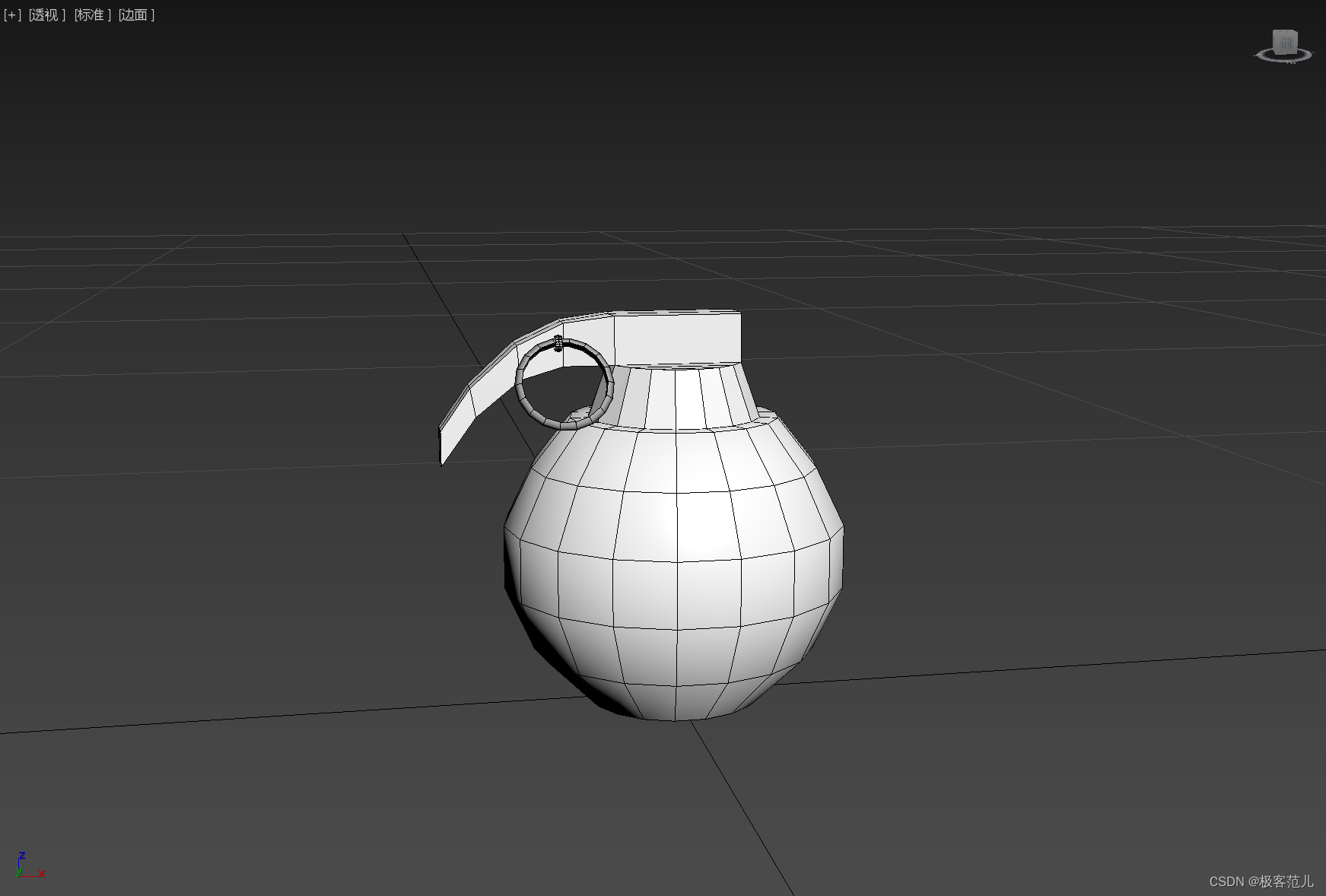
- One 、 Create a projectile model
- 1、 View -〉 Viewport configuration -〉 Layout -〉 Choose left and right
- 2、 The upper left corner of the left view , Select left 、 Plane + highlights + Side face ( It's best to change the view direction on the left , Do not rotate at will )
- 3、 The upper left corner of the right view , Choose perspective 、 Plane + highlights + Side face ( You can use the upper right turntable to rotate at will )
- 4、 Press +, Hidden grid , Maximize the view
- 5、 establish -> Basic geometry -> The ball , Rename it to grenade
- 6、 Set in the modifier panel : radius :48, piecewise :16( The default value is 32, Not conducive to operation )
- 7、 Right click the sphere -〉 Convert to -〉 Convert to editable poly
- 8、 Switch the left view to the top view , In the rollout ( Editable poly ) Select polygon , Select the upper and lower faces of the sphere , Press Delete Key to delete
- 9、 The border ->Ctrl+A Select all sphere objects , The actual two boundaries in the object are shown in red
- 10、 Edit boundary ( Select the boundary in editable poly ) -> Seal , Add a definite face to the object
- 11、 Press the shortcut key 6, Deselect the sphere object layer
- 12、 Click... In the toolbar “ Select and scale evenly ”, Along the Z Pull the sphere object upwards
- 13、 Click... In the toolbar “ Select and move ”-〉 Press down 4, Enter polygon level -〉 Select the top face
- 14、 edit poly -〉 Insert -〉 Set up Inset=8, single click √, Complete the insert operation
- 15、 edit poly -〉 Chamfering -〉 Set up Hight=14,Outline=-7, single click √, Finish chamfer
- 16、 Press down 1, Enter the vertex level -〉 Press down T, Switch to the top view -〉 choice -〉 choose “ Ignore Backfacing ”
- 17、 Select the two points on the top left of the sphere -〉 Edit vertices -〉 Connect , Connect the selected points
- 18、 Press down 4, Enter polygon level -〉 Select the top middle face -〉 Chamfering -〉 Set up Hight=14,Outline=-1, single click √, Finish chamfer
- 19、 Select the two faces on the left side of the top -〉 edit poly -〉 Squeeze out -〉 Hight=10 , single click √
- Two 、 Create a fuze model
- 1、 Press down 2, Enter the edge level -〉 Select an edge in the middle of the left projection -〉 Press Ctrl+Backspace, Delete the selected edge and the extra points on the edge , Become a plane
- 2、 Press down 1, Enter the vertex level -〉 Press L, Switch to the left view -〉 Select the top two points on the left -〉 Use “ Select and move ” Tools , Move the selected point down and left
- 3、 Select the four points on the left -〉 Edit vertices -〉 Connect , Connect the four selected points
- 4、 Press down 4, Enter polygon level -〉 Select the face below the protrusion of the object -〉 Squeeze out -〉 Set up Hight=10, single click √, Finish extruding
- 5、 Press down 1, Enter the vertex level -〉 Press L, Switch to the left view -〉 Select the point of the protruding part -〉 Use “ Select and move ” Tools , Move the selected point at a certain distance and angle from the main part
- 6、 Repeat the above two steps , Squeeze it out twice , The handle of the grenade is finished
- 3、 ... and 、 Create insurance pin model
- 1、 Press down L, Switch to the left view -〉 establish -〉 Standard primitives -〉 ring
- 2 Drag and drop the mouse to create a circle , name Torus001,Radius 1=20,Radius 2=1.2, Segments=10, Sides=6
- 3、 Drag and drop the mouse to create a circle , name Torus002,Radius 1=2.5,Radius 2=0.8, Segments=10, Sides=6
- 4、 establish -〉 Standard primitives -〉 Cylinder
- 5、 Drag the mouse to create a cylinder ( Pull out the garden , Release the mouse and then press and pull ), Radius =1.2,Height=0.8, Height Segments=1, Sides=6
- 6、 Use “ Select and move ” and “ Select and rotate ” Tools , Move two rings and cylinders , Combined into the shape of the pull ring of the grenade ( First, rotate and translate in all directions on the perspective on the right , Then select the left view on the left , Put the parts in place , Then change to the front view , Put the parts in place .)
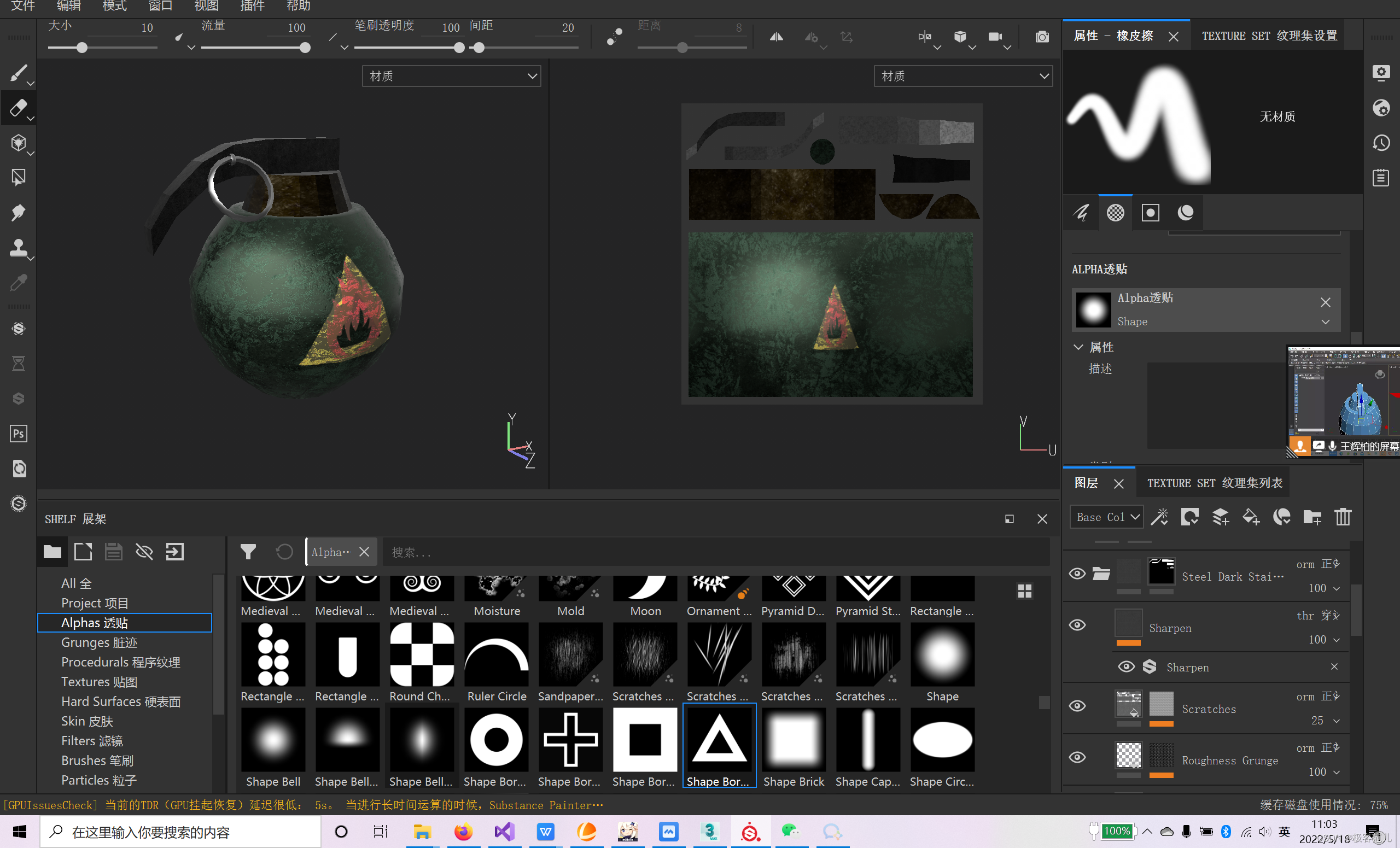
- Four 、UV Expand add material
- 1、 Press M( Or select the material editor from the icon in the upper right corner ), Select a shader on the material editor panel
- 2、Blinn The basic parameters -〉“ Diffuse reflection ” The map selection button on the right -〉 In the pop-up “ texture of material / Map browser ” Choose from “ Bitmap ”, single click “OK”
- 3、 In the pop-up “ Select bitmap image file ” Select... In the dialog box grenade.bmp, single click “ open ”, Determine the selection of the map file
- 4、 Click... In the material editor “ Assign materials to selected objects ” Button ( The... Below the shader 3 Button ), Hold the shader and drag it until the object is released , At this time, the map is not displayed on the object. Click... In the material editor “ Display the standard map in the viewport ” Button ( The... Below the shader 9 Button ), View the addition of model mapping in the perspective
- 5、 Select the grenade object -〉 modify -〉“ Modifier list ” The drop button on the right -〉 choice “UVW an ” Map modifier -〉 Click on “ edit …”-〉 Show “ edit UVW” window -〉 Select the map display mode in the upper right corner as “Map#0(grenade.bmp)”, That is, map expansion and model mesh routing are displayed in this panel
- 6、 Click on “ edit UVW” Below the window “ Choice mode ” On the far right “ Face sub object mode ”, Modify the mapping information of the model in the scene in face mode
- 5、 ... and 、 summary
One 、 Create a projectile model
1、 View -〉 Viewport configuration -〉 Layout -〉 Choose left and right
2、 The upper left corner of the left view , Select left 、 Plane + highlights + Side face ( It's best to change the view direction on the left , Do not rotate at will )
3、 The upper left corner of the right view , Choose perspective 、 Plane + highlights + Side face ( You can use the upper right turntable to rotate at will )
4、 Press +, Hidden grid , Maximize the view
5、 establish -> Basic geometry -> The ball , Rename it to grenade
6、 Set in the modifier panel : radius :48, piecewise :16( The default value is 32, Not conducive to operation )
7、 Right click the sphere -〉 Convert to -〉 Convert to editable poly
8、 Switch the left view to the top view , In the rollout ( Editable poly ) Select polygon , Select the upper and lower faces of the sphere , Press Delete Key to delete
9、 The border ->Ctrl+A Select all sphere objects , The actual two boundaries in the object are shown in red
10、 Edit boundary ( Select the boundary in editable poly ) -> Seal , Add a definite face to the object
11、 Press the shortcut key 6, Deselect the sphere object layer
12、 Click... In the toolbar “ Select and scale evenly ”, Along the Z Pull the sphere object upwards
13、 Click... In the toolbar “ Select and move ”-〉 Press down 4, Enter polygon level -〉 Select the top face
14、 edit poly -〉 Insert -〉 Set up Inset=8, single click √, Complete the insert operation
15、 edit poly -〉 Chamfering -〉 Set up Hight=14,Outline=-7, single click √, Finish chamfer
16、 Press down 1, Enter the vertex level -〉 Press down T, Switch to the top view -〉 choice -〉 choose “ Ignore Backfacing ”
17、 Select the two points on the top left of the sphere -〉 Edit vertices -〉 Connect , Connect the selected points
18、 Press down 4, Enter polygon level -〉 Select the top middle face -〉 Chamfering -〉 Set up Hight=14,Outline=-1, single click √, Finish chamfer
19、 Select the two faces on the left side of the top -〉 edit poly -〉 Squeeze out -〉 Hight=10 , single click √
Two 、 Create a fuze model
1、 Press down 2, Enter the edge level -〉 Select an edge in the middle of the left projection -〉 Press Ctrl+Backspace, Delete the selected edge and the extra points on the edge , Become a plane
( The deletion effect is better from the perspective , Notice that the left and right sides are different )
2、 Press down 1, Enter the vertex level -〉 Press L, Switch to the left view -〉 Select the top two points on the left -〉 Use “ Select and move ” Tools , Move the selected point down and left
3、 Select the four points on the left -〉 Edit vertices -〉 Connect , Connect the four selected points
4、 Press down 4, Enter polygon level -〉 Select the face below the protrusion of the object -〉 Squeeze out -〉 Set up Hight=10, single click √, Finish extruding
5、 Press down 1, Enter the vertex level -〉 Press L, Switch to the left view -〉 Select the point of the protruding part -〉 Use “ Select and move ” Tools , Move the selected point at a certain distance and angle from the main part
( Change the angle of the face by moving two points on one edge of the face , Move the four points on the face to make the face stretch , The adjusted surface is used as the extrusion datum , It's best to choose a point after changing the perspective on the perspective , Move from the left view )
6、 Repeat the above two steps , Squeeze it out twice , The handle of the grenade is finished
3、 ... and 、 Create insurance pin model
1、 Press down L, Switch to the left view -〉 establish -〉 Standard primitives -〉 ring
2 Drag and drop the mouse to create a circle , name Torus001,Radius 1=20,Radius 2=1.2, Segments=10, Sides=6
3、 Drag and drop the mouse to create a circle , name Torus002,Radius 1=2.5,Radius 2=0.8, Segments=10, Sides=6
4、 establish -〉 Standard primitives -〉 Cylinder
5、 Drag the mouse to create a cylinder ( Pull out the garden , Release the mouse and then press and pull ), Radius =1.2,Height=0.8, Height Segments=1, Sides=6
6、 Use “ Select and move ” and “ Select and rotate ” Tools , Move two rings and cylinders , Combined into the shape of the pull ring of the grenade ( First, rotate and translate in all directions on the perspective on the right , Then select the left view on the left , Put the parts in place , Then change to the front view , Put the parts in place .)
Four 、UV Expand add material
1、 Press M( Or select the material editor from the icon in the upper right corner ), Select a shader on the material editor panel
2、Blinn The basic parameters -〉“ Diffuse reflection ” The map selection button on the right -〉 In the pop-up “ texture of material / Map browser ” Choose from “ Bitmap ”, single click “OK”
3、 In the pop-up “ Select bitmap image file ” Select... In the dialog box grenade.bmp, single click “ open ”, Determine the selection of the map file
4、 Click... In the material editor “ Assign materials to selected objects ” Button ( The... Below the shader 3 Button ), Hold the shader and drag it until the object is released , At this time, the map is not displayed on the object. Click... In the material editor “ Display the standard map in the viewport ” Button ( The... Below the shader 9 Button ), View the addition of model mapping in the perspective
5、 Select the grenade object -〉 modify -〉“ Modifier list ” The drop button on the right -〉 choice “UVW an ” Map modifier -〉 Click on “ edit …”-〉 Show “ edit UVW” window -〉 Select the map display mode in the upper right corner as “Map#0(grenade.bmp)”, That is, map expansion and model mesh routing are displayed in this panel
6、 Click on “ edit UVW” Below the window “ Choice mode ” On the far right “ Face sub object mode ”, Modify the mapping information of the model in the scene in face mode
Click on 3D The face in the figure , Display the corresponding area in the bitmap , Move each vertex position , send 2D Graphics and 3D Model matching
5、 ... and 、 summary
Mapping software is recommended Substance Painter, The design of the coating combines it with the updated seamless material sample project . Polygon modeling is suitable for building models with edges and corners , For example, this grenade model , It is also suitable for building models with smooth surface changes . Polygon modeling is a complete modeling process , It can't be accomplished with oneortwo commands . This blog uses the most commands in polygon modeling .
边栏推荐
- Initial experience of domestic database tidb: simple and easy to use, quick to start
- Performance test of Gatling
- 无心剑中译伊丽莎白·毕肖普《一门技艺》
- Hidden corners of coder Edition: five things that developers hate most
- [HCIA continuous update] WLAN overview and basic concepts
- Is it safe for CITIC Securities to open an account online? Is the account opening fee charged
- [system analyst's road] Chapter 7 double disk system design (structured development method)
- 离线、开源版的 Notion—— 笔记软件Anytype 综合评测
- 智捷云——元宇宙综合解决方案服务商
- Ks007 realizes personal blog system based on JSP
猜你喜欢


随机推荐
Flask lightweight web framework
The top half and bottom half of the interrupt are introduced and the implementation method (tasklet and work queue)
Is it safe for Bank of China Securities to open an account online?
R language plot visualization: plot visualization of multiple variable violin plot in R with plot
Talk about seven ways to realize asynchronous programming
The 18th IET AC / DC transmission International Conference (acdc2022) was successfully held online
wuzhicms代码审计
Pytorch深度学习之环境搭建
上网成瘾改变大脑结构:语言功能受影响,让人话都说不利索
【每日一题】556. 下一个更大元素 III
设置窗体透明 隐藏任务栏 与全屏显示
[unity ugui] scrollrect dynamically scales the grid size and automatically locates the middle grid
kaili不能输入中文怎么办???
Implementation of super large-scale warehouse clusters in large commercial banks
78岁华科教授冲击IPO,丰年资本有望斩获数十倍回报
【HCIA持续更新】广域网技术
为啥有些线上演唱会总是怪怪的?
VB cannot access database stocks
To sort out messy header files, I use include what you use
【HCIA持续更新】WLAN工作流程概述