当前位置:网站首页>Verilog design responder [with source code]
Verilog design responder [with source code]
2022-07-07 11:15:00 【Lime Miya】
Answering machine design
1、 The experiment platform
 Software :PC、Quartus Prime 18.1、Modelsim 10.5b
 Hardware :Altera FPGA Development board (EP4CE6E22F17C8)
2、 The experiment purpose
- 1、 Master the dynamic refresh principle of nixie tube
- 2、 Logic exercises
2.1、 Experimental content
 Based on 8 position 8 A digital tube and 4 A mechanical key , Make a answering machine , The requirements are as follows :
1、	 Set four keys , Three of them A、B、C, host 0;
2、	 The host has the permission to clear all States
3、	 After each rush to answer , Players need to be 10S Make a choice , No test is regarded as giving up , Once a contestant presses the button , The keys of the other two players will fail
4、	 If there is no contestant to answer , The nixie tube shows 10s count down , At the end of the time ,LED Keep blinking ; meanwhile , All players' keys fail , Until the host starts again
5、	 The leftmost display shows the countdown , The lower three places, from left to right, represent the contestants ABC, When a contestant answers , The corresponding characters will be displayed (A or B or C), At the same time, the countdown pauses , Until the host presses , All States are restored , Start a new round of answer .
3、 Experimental process
3.1、 Experimental principle
According to the schematic diagram of the development board , The following information is available
Nixie tube : It is essentially a group of light-emitting diodes arranged in a certain order , Its display principle and LED It's no different .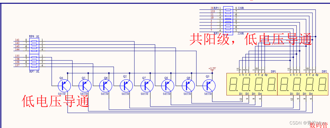
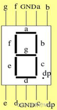
 According to the hardware schematic diagram , Light-emitting diode , All anodes are switched on 3.3V Positive voltage of , That is to say — High level , So if we want to
 If the LED is on , It is necessary to turn on the low level at the cathode , You can make LED Light up .
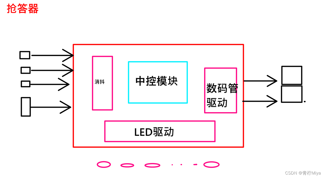
3.2、 System architecture
According to the system requirements , The following frame distribution can be obtained
3.3、 Sub function module design
Build according to the system , The following modules are available
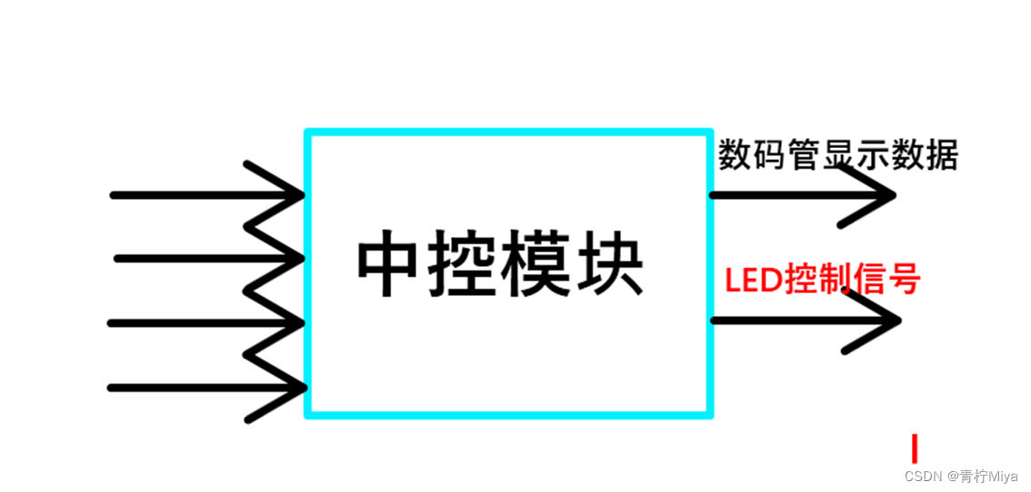
3.3.1、 Central control module
Block diagram
Signal definition
| Signal name | Port type | Data bit width | Signal description |
|---|---|---|---|
| Clk | i | 1 | Input clock signal ,50MHz |
| Rst_n | i | 1 | Input reset signal , Low level active |
| key_A | i | 1 | player A Key |
| key_B | i | 1 | player B Key |
| key_C | i | 1 | player C Key |
| key_0 | i | 1 | Host button |
| Data_time | O | 16 | 10s Countdown data |
| Led_en | O | 1 | The countdown is over , Can make LED flashing |
Design documents
/*================================================*\ Filename ﹕ctrl_mode.v Author ﹕Adolph Description ﹕ Central control module , Command parsing , Data display control  Called by ﹕responder.v Revision History ﹕ 2022-6-20 15:20:43 Revision 1.0 Email﹕[email protected] Company﹕ \*================================================*/
module ctrl_mode(
	input				clk		,
	input				rst_n	,
	input		[3:0] 	key_ctrl, // Key debounce signal

	output		[3:0]	data	,
	output	reg [3:0] 	key_sta	, // Key status signal
	output	reg  		led_en
);
//parameter declarations
	parameter TIME_S = 26'd50_000_000;

//internal reg / wire signals
	reg 	[25:0]	cnt_1s	 ;
	wire			add_1s	 ;
	wire			end_1s	 ;
	reg				latch_log;

	reg		[3:0]	cnt_delay;// Show 9-0
	wire			add_delay;
	wire			end_delay;

	assign data   = cnt_delay;
// assign led_en = end_delay;
	[email protected](posedge clk or negedge rst_n)begin
		if(!rst_n)begin
			led_en <= 1'b0;
		end
		else if(key_ctrl[0])begin
			led_en <= 1'b0;
		end
		else if(end_delay)begin
			led_en <= 1'b1;
		end
		else begin
			led_en <= led_en;
		end
	end

	[email protected](posedge clk or negedge rst_n)begin
		if(!rst_n)begin
			key_sta <= 4'b0000;
		end
		else if(key_ctrl[0])begin // After the host presses the key
			key_sta <= 4'b0001;
		end
		else if(latch_log)begin
			key_sta <= key_sta;
		end
		else begin
			case(key_ctrl)
				4'b0010:key_sta[1] <= 1'b1;
				4'b0100:key_sta[2] <= 1'b1;
				4'b1000:key_sta[3] <= 1'b1;
				default: ;
			endcase
		end
	end

	[email protected](posedge clk or negedge rst_n)begin
		if(!rst_n)begin
			latch_log <= 1'b1; // After initial power on , Lock in effect
		end
		else if(key_ctrl[0])begin // Host press , Lock failure , Players press valid
			latch_log <= 1'b0;
		end
		else if(key_ctrl[1] || key_ctrl[2] || key_ctrl[3] || end_delay)begin // After any player presses , Lock in effect ; The countdown is over , Players are also not allowed to press buttons
			latch_log <= 1'b1;
		end
		else begin
			latch_log <= latch_log;
		end
	end

	[email protected](posedge clk or negedge rst_n)begin
		if(!rst_n)begin
			cnt_1s <= 'd0;
		end
		else if(add_1s)begin
			if(end_1s)begin
				cnt_1s <= 'd0;
			end
			else begin
				cnt_1s <= cnt_1s + 26'd1;
			end
		end
		else begin
			cnt_1s <= cnt_1s;
		end
	end

	assign add_1s = key_sta == 4'b0001;
	assign end_1s = add_1s && cnt_1s >= TIME_S - 'd1;


	[email protected](posedge clk or negedge rst_n)begin
		if(!rst_n)begin
			cnt_delay <= 'd10;
		end
		else if(key_ctrl[0])begin
			cnt_delay <= 'd10;
		end
		else if(add_delay)begin
			if(end_delay)begin
				cnt_delay <= cnt_delay;
			end
			else begin
				cnt_delay <= cnt_delay - 4'd1;
			end
		end
		else begin
			cnt_delay <= cnt_delay;
		end
	end

	assign add_delay = end_1s;
	assign end_delay = add_delay && cnt_delay == 'd1 - 'd1;

endmodule
This module is relatively simple , Simulation verification is not done here , If you are interested, you can verify by yourself
3.3.2、 Digital tube driver module
The drive of the digital tube area has been changed on the basis of the previous , You understand it yourself
Design documents
/*================================================*\ Filename ﹕seg_driver.v Author ﹕Adolph Description ﹕ Decode the input data , And drive the nixie tube to display the corresponding data  Called by ﹕responder.v Revision History ﹕ 2022-5-30 14:27:22 Revision 1.0 Email﹕[email protected] Company﹕ \*================================================*/
module seg_driver(
	input				clk		,
	input				rst_n	,
	input		[03:0]	key_ctrl,

	input	  	[31:0]	dis_data,// Countdown data
	output reg	[07:0]	dig_sel	,
	output reg	[07:0]	dig_seg
);
//wire [31:0]dis_data;


// assign dig_seg = 8'd0;
// assign dig_sel = 1'b0;
	localparam
		NUM_0  	= 8'hC0,
		NUM_1  	= 8'hF9,
		NUM_2  	= 8'hA4,
		NUM_3  	= 8'hB0,
		NUM_4  	= 8'h99,
		NUM_5  	= 8'h92,
		NUM_6  	= 8'h82,
		NUM_7  	= 8'hF8,
		NUM_8  	= 8'h80,
		NUM_9  	= 8'h90,
		NUM_A  	= 8'h88,
		NUM_B  	= 8'h83,
		NUM_C  	= 8'hC6,
		NUM_D  	= 8'hA1,
		NUM_E  	= 8'h86,
		NUM_F  	= 8'h8E,
		LIT_ALL	= 8'h00,
		BLC_ALL	= 8'hFF;
	parameter CNT_REF = 25'd1000;

	reg	[9:0]	cnt_20us; //20us Counter
	reg	[4:0] 	data_tmp; // It is used to get the display data of different bit selections

// assign dis_data = 32'hABCD_4413;
// Describe bit selection signal switching
	// Description refresh counter
	[email protected](posedge clk or negedge rst_n)begin
		if(!rst_n)begin
			cnt_20us <= 10'd0;
		end
		else if(cnt_20us >= CNT_REF - 10'd1)begin
			cnt_20us <= 10'd0;
		end
		else begin
			cnt_20us <= cnt_20us + 10'd1;
		end
	end

	[email protected](posedge clk or negedge rst_n)begin
		if(!rst_n)begin
			dig_sel <= 8'hfe;//8'b1111_1110
		end
		else if(cnt_20us >= CNT_REF - 10'd1)begin
			dig_sel <= {
    dig_sel[6:0],dig_sel[7]};
		end
		else begin
			dig_sel <= dig_sel;
		end
	end

// Segment selection signal description
	[email protected](posedge clk or negedge rst_n)begin
		if(!rst_n)begin
			data_tmp <= 5'd0;
		end
		else if(key_ctrl[0])begin
			data_tmp <= 5'h10;
		end
		else begin
			case(dig_sel)
				8'b1111_1110: begin
								if(key_ctrl[3])
									data_tmp <= 5'hc;
								else
									data_tmp <= 5'h10;
							end
				8'b1111_1101: begin
								if(key_ctrl[2])
									data_tmp <= 5'hb;
								else
									data_tmp <= 5'h10;
							end
				8'b1111_1011: begin
								if(key_ctrl[1])
									data_tmp <= 5'ha;
								else
									data_tmp <= 5'h10;
							end
				8'b1111_0111:data_tmp <= 5'h10;
				8'b1110_1111:data_tmp <= 5'h10;
				8'b1101_1111:data_tmp <= 5'h10;
				8'b1011_1111:data_tmp <= 5'h10;
				8'b0111_1111:data_tmp <= dis_data[3-:4];
				default: data_tmp <= 5'hF;
			endcase
		end
	end

	[email protected](posedge clk or negedge rst_n)begin
		if(!rst_n)begin
			dig_seg <= LIT_ALL;
		end
		else begin
			case(data_tmp)
				5'h0 : dig_seg <= NUM_0;
				5'h1 : dig_seg <= NUM_1;
				5'h2 : dig_seg <= NUM_2;
				5'h3 : dig_seg <= NUM_3;
				5'h4 : dig_seg <= NUM_4;
				5'h5 : dig_seg <= NUM_5;
				5'h6 : dig_seg <= NUM_6;
				5'h7 : dig_seg <= NUM_7;
				5'h8 : dig_seg <= NUM_8;
				5'h9 : dig_seg <= NUM_9;
				5'hA : dig_seg <= NUM_A;
				5'hB : dig_seg <= NUM_B;
				5'hC : dig_seg <= NUM_C;
				5'hD : dig_seg <= NUM_D;
				5'hE : dig_seg <= NUM_E;
				5'hF : dig_seg <= NUM_F;
				5'h10: dig_seg <= BLC_ALL;
				default:dig_seg <= LIT_ALL;
			endcase
		end
	end

endmodule
3.3.3 LED Driver module
Design documents
module led_water(
	input 				clk		,//50MHz
	input				rst_n	,//low valid
	input				blink_en,// Flashing enable signal

	output	reg	[7:0]	led_o
);
// Parameters are defined
	parameter CNT_MAX = 25'd500_0000;

// Signal definition
	reg		[24:0] 	cnt;//500ms Counter , Count maximum  2500_0000,

	// timing  0-500ms
	[email protected](posedge clk or negedge rst_n)begin
		if(!rst_n)
			cnt <= 25'd0;
		else if(blink_en)begin
			if(cnt >= CNT_MAX - 25'd1)
				cnt <= 25'd0;
			else
				cnt <= cnt + 1'b1;
		end
		else
			cnt <= 25'd0;
	end

	//led  Output
	[email protected](posedge clk or negedge rst_n)begin
		if(!rst_n)
			led_o <= 8'b0000_0000; //all light
		else if(blink_en)begin
			if(cnt >= CNT_MAX - 25'd1)
				led_o <= ~led_o;
			else
				led_o <= led_o; //s
		end
		else begin
			led_o <= 8'b0000_0000;
		end
	end
endmodule
3.3.4、 Key anti shake module
This module has been designed before , There is no repetition here , Refer to shaking verilog Realize key elimination
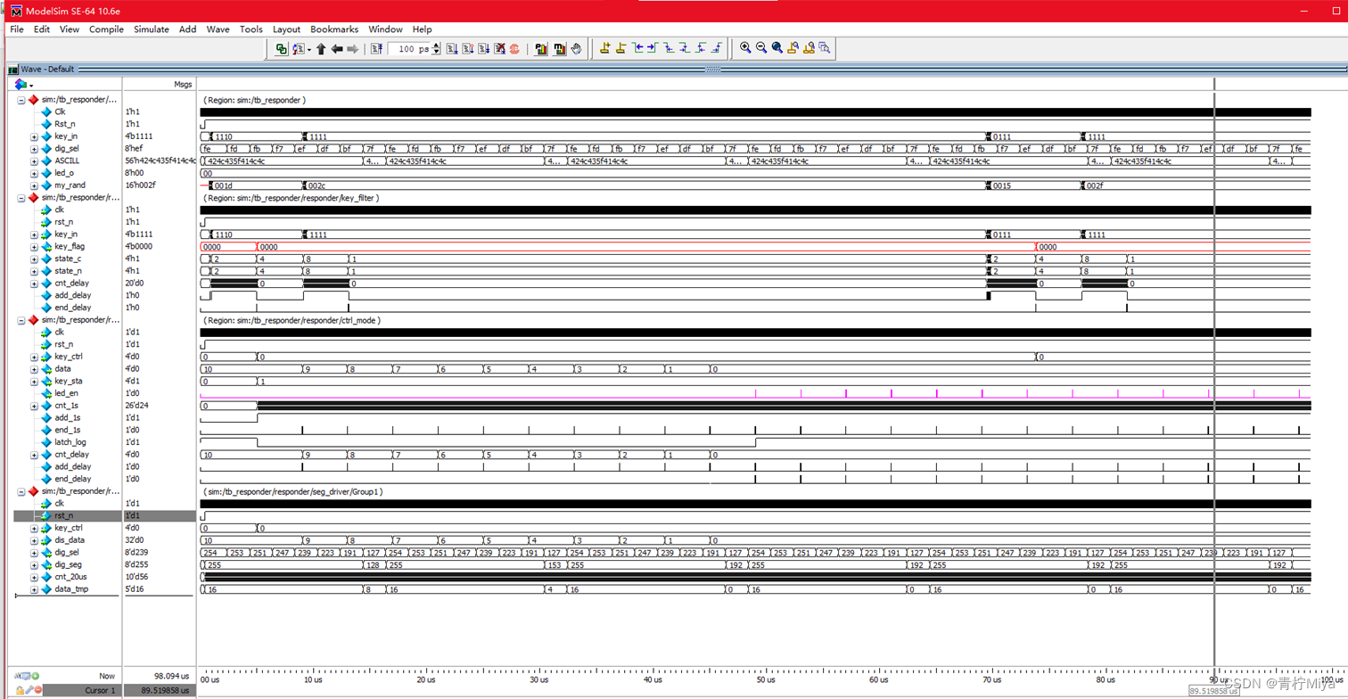
3.4 Simulation verification
`timescale 1ns/1ns 		// Simulation system time scale definition

`define clk_period 20  	// Clock cycle parameter definition

module tb_responder();
// Excitation signal definition
	reg				Clk		;
	reg				Rst_n	;
	reg		[3:00]	key_in	; //

// Response signal definition
	wire 	[7:0]	dig_sel	;
	wire 	[7:0]	dig_seg	;
	wire 	[7:0]	led_o   ;

	defparam responder.DELAY_TIME = 200;
	defparam responder.ctrl_mode.TIME_S = 200;
	defparam responder.seg_driver.CNT_REF = 100;

	reg		[55:00]	ASCILL; //

	localparam
		NUM_0  	= 8'hC0,
		NUM_1  	= 8'hF9,
		NUM_2  	= 8'hA4,
		NUM_3  	= 8'hB0,
		NUM_4  	= 8'h99,
		NUM_5  	= 8'h92,
		NUM_6  	= 8'h82,
		NUM_7  	= 8'hF8,
		NUM_8  	= 8'h80,
		NUM_9  	= 8'h90,
		NUM_A  	= 8'h88,
		NUM_B  	= 8'h83,
		NUM_C  	= 8'hC6,
		NUM_D  	= 8'hA1,
		NUM_E  	= 8'h86,
		NUM_F  	= 8'h8E,
		LIT_ALL	= 8'h00,
		BLC_ALL	= 8'hFF;
	[email protected](*)begin
		case(responder.seg_driver.dig_seg)
			NUM_0  	: ASCILL = "NUM_0 ";
			NUM_1  	: ASCILL = "NUM_1 ";
			NUM_2  	: ASCILL = "NUM_2 ";
			NUM_3  	: ASCILL = "NUM_3 ";
			NUM_4  	: ASCILL = "NUM_4 ";
			NUM_5  	: ASCILL = "NUM_5 ";
			NUM_6  	: ASCILL = "NUM_6 ";
			NUM_7  	: ASCILL = "NUM_7 ";
			NUM_8  	: ASCILL = "NUM_8 ";
			NUM_9  	: ASCILL = "NUM_9 ";
			NUM_A  	: ASCILL = "NUM_A ";
			NUM_B  	: ASCILL = "NUM_B ";
			NUM_C  	: ASCILL = "NUM_C ";
			NUM_D  	: ASCILL = "NUM_D ";
			NUM_E  	: ASCILL = "NUM_E ";
			NUM_F  	: ASCILL = "NUM_F ";
			LIT_ALL	: ASCILL = "LIT_ALL";
			BLC_ALL	: ASCILL = "BLC_ALL";
			default : ASCILL = "LIT_ALL";
		endcase
	end

// Instantiation
	responder	responder(
		/*input */.clk		(Clk	),
		/*input */.rst_n	(Rst_n	),
		/*input [3:0] */.key_in	(key_in	), // Key debounce signal

		/*output [7:0] */.dig_sel	(dig_sel),
		/*output [7:0] */.dig_seg	(dig_seg),
		/*output [7:0] */.led_o    (led_o  )
	);

// Make a clock
	initial Clk = 1'b0;
	always #(`clk_period / 2) Clk = ~Clk;

// Generate incentives
	initial  begin
		Rst_n = 1'b0;
		key_in = 4'b1111;
		#(`clk_period * 20 + 3);
		Rst_n = 1'b1;
		#(`clk_period * 20);

		press_key0;
		#(`clk_period * 2000);
		press_key3;
		$stop(2);
	end

	reg	[15:0]	my_rand;
	task	press_key0 ;
		begin
			// Front jitter
			repeat(10)begin
				my_rand = {
    $random} % 50	;
				#my_rand key_in[0] = ~key_in[0];
			end

			key_in[0] = 1'b0;
			#(400 * `clk_period);	//21ms > 20ms

			// Post jitter
			repeat(11)begin
				my_rand = {
    $random} % 50	;
				#my_rand key_in[0] = ~key_in[0];
			end

			key_in[0] = 1'b1;
			#(1000 * `clk_period);	//21ms > 20ms

		end
	endtask

	task	press_key1 ;
		begin
			// Front jitter
			repeat(19)begin
				my_rand = {
    $random} % 50	;
				#my_rand key_in[1] = ~key_in[1];
			end

			key_in[1] = 1'b0;
			#(400 * `clk_period);	//21ms > 20ms

			// Post jitter
			repeat(10)begin
				my_rand = {
    $random} % 50	;
				#my_rand key_in[1] = ~key_in[1];
			end

			key_in[1] = 1'b1;
			#(1000 * `clk_period);	//21ms > 20ms

		end
	endtask

	task	press_key2 ;
		begin
			// Front jitter
			repeat(13)begin
				my_rand = {
    $random} % 50	;
				#my_rand key_in[2] = ~key_in[2];
			end

			key_in[2] = 1'b0;
			#(400 * `clk_period);	//21ms > 20ms

			// Post jitter
			repeat(10)begin
				my_rand = {
    $random} % 50	;
				#my_rand key_in[2] = ~key_in[2];
			end

			key_in[2] = 1'b1;
			#(1000 * `clk_period);	//21ms > 20ms

		end
	endtask

	task	press_key3 ;
		begin
			// Front jitter
			repeat(15)begin
				my_rand = {
    $random} % 50	;
				#my_rand key_in[3] = ~key_in[3];
			end

			key_in[3] = 1'b0;
			#(400 * `clk_period);	//21ms > 20ms

			// Post jitter
			repeat(11)begin
				my_rand = {
    $random} % 50	;
				#my_rand key_in[3] = ~key_in[3];
			end

			key_in[3] = 1'b1;
			#(1000 * `clk_period);	//21ms > 20ms

		end
	endtask
endmodule
3.4、 Board level verification
3.4.1、 Top level documents
The top-level document is not explained here , According to the following RTL View , I believe that readers can easily complete the corresponding code design
RTL View 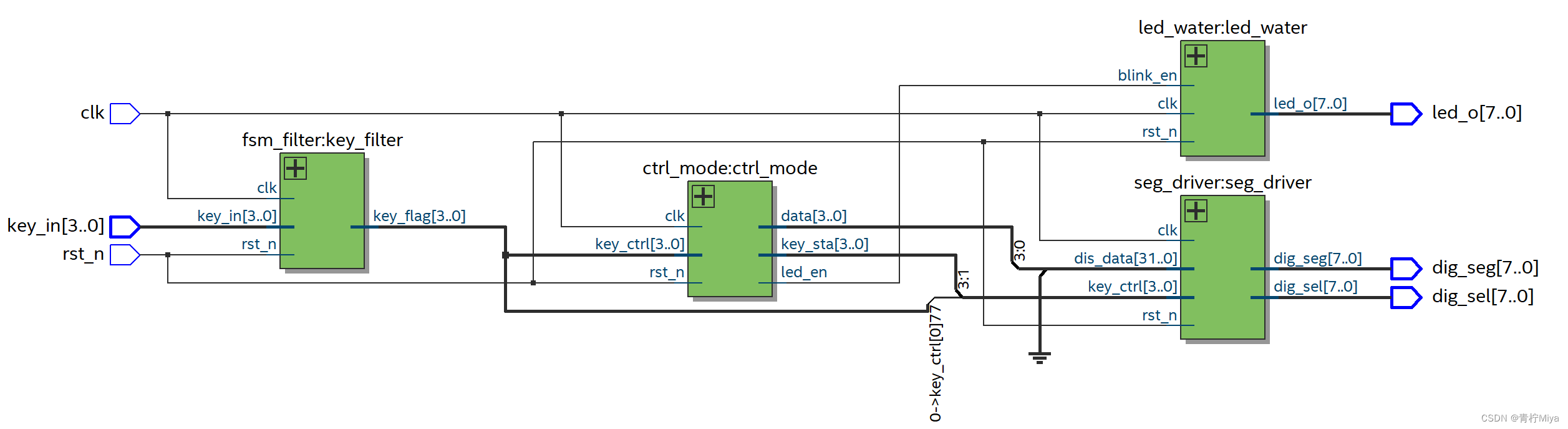
The specific implementation effect is as expected , Please explore by yourself
4、 summary
 This design realizes the basic functions
 In the design process , Due to bit width mismatch (quartus No mistake. , Warning only ), Cause the program to run incorrectly , The specific reason can only be determined after several times of error detection
 so , I warn you , When describing signals , Be sure to match the bit width
边栏推荐
- 使用引用
- [machine learning 03] Lagrange multiplier method
- 基于DE2 115开发板驱动HC_SR04超声波测距模块【附源码】
- Compile QT project script with qmake
- "Dream Cup" 2017 Jiangsu information and future primary school summer camp it expert PK program design questions
- Socket socket programming
- 2022.7.4DAY596
- seata 1.3.0 四种模式解决分布式事务(AT、TCC、SAGA、XA)
- Input type= "password" how to solve the problem of password automatically brought in
- Transaction rolled back because it has been marked as rollback-only解决
猜你喜欢
"Dream Cup" 2017 Jiangsu information and future primary school summer camp it expert PK program design questions
Socket socket programming
基于华为云IOT设计智能称重系统(STM32)
![[STM32] actual combat 3.1 - drive 42 stepper motors with STM32 and tb6600 drivers (I)](/img/cd/7cd8e2e77419c65d633a2a235b2362.png)
[STM32] actual combat 3.1 - drive 42 stepper motors with STM32 and tb6600 drivers (I)
【STM32】实战3.1—用STM32与TB6600驱动器驱动42步进电机(一)
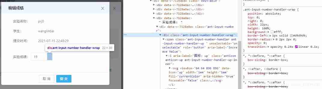
How to remove addition and subtraction from inputnumber input box
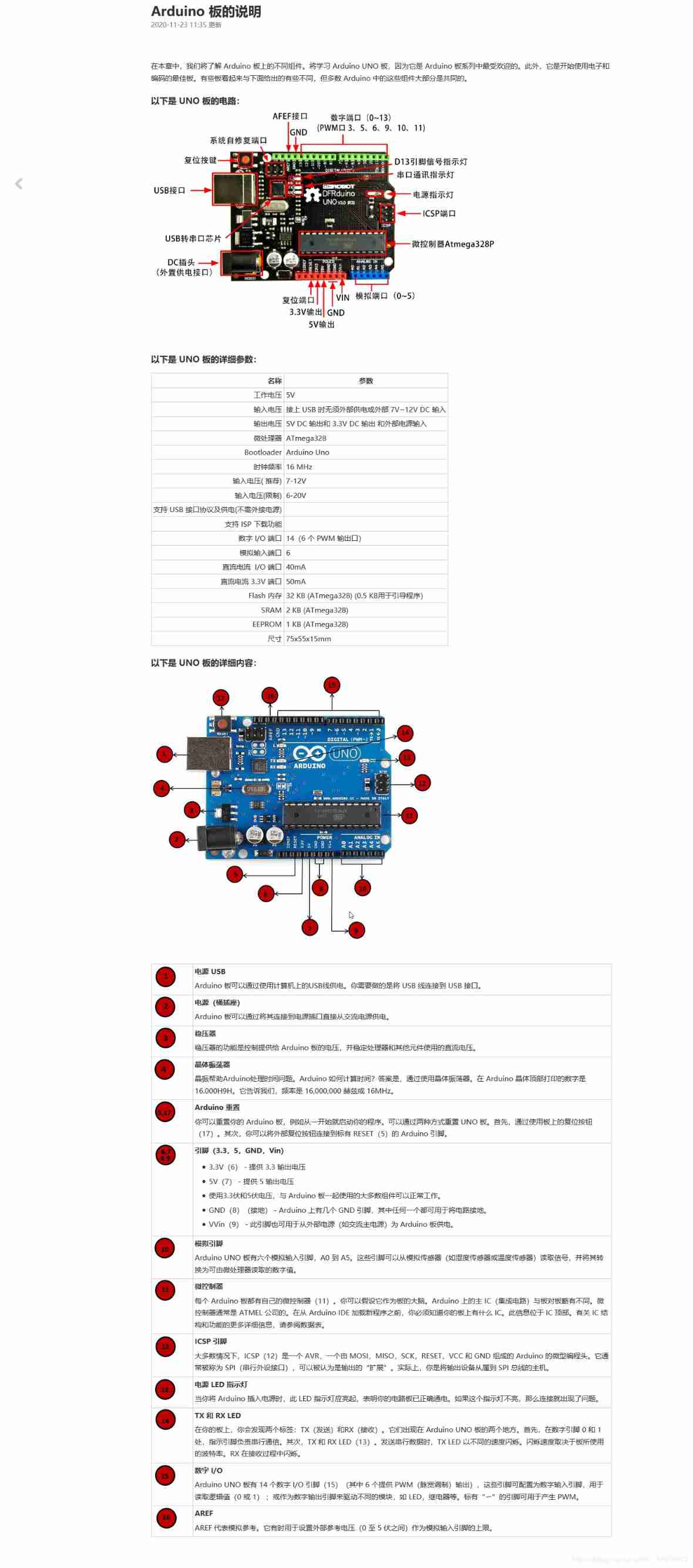
Arduino board description
2021 summary and 2022 outlook
如何在博客中添加Aplayer音乐播放器
Antd select selector drop-down box follows the scroll bar to scroll through the solution
随机推荐
JSON format query of MySQL
[untitled]
V-for img SRC rendering fails
解决VSCode只能开两个标签页的问题
Go redis Middleware
Basic knowledge of process (orphan, zombie process)
SQL Server knowledge gathering 9: modifying data
The opacity value becomes 1%
基于STC8G1K08的0.96寸IIC液晶屏驱动程序
关于在云服务器上(这里用腾讯云)安装mysql8.0并使本地可以远程连接的方法
Unity websocket server
Go slice comparison
uniCloud
数据库同步工具 DBSync 新增对MongoDB、ES的支持
verilog设计抢答器【附源码】
uniCloud
Unity script visualization about layout code
使用引用
从色情直播到直播电商
Graduation season | keep company with youth and look forward to the future together!