当前位置:网站首页>Iii. Système de démarrage et d'horloge à puce
Iii. Système de démarrage et d'horloge à puce
2022-07-02 11:07:00 【L'eau de la voiture est épaisse.】
Système de démarrage et d'horloge à puce
1.Activation de la puce
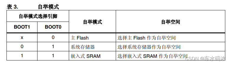
Tout d'abord,stm32Selon le mode de démarrage(Manuel de référence2.4Section)Charger le Code de démarrage en mémoire à partir de l'emplacement de démarrage,Démarrer l'exécution du Code de démarrage après,En général, le Code de démarrage est fourni officiellement. ---------- xxx.s
Démarrer le travail du Code:
Initialisation de l'espace de pile,Définir la table des vecteurs d'exception AppelezSystemInit ----------- Initialisation du système Initialisation de l'horloge,Ajuster la table des vecteurs d'exception Mise en œuvremain ---------- Fonction principale
La puce va commencer à fonctionner.,L'horloge et la mémoire doivent être initialisées,stm32Utilisation de la mémoire dans la puceSRAM,Peut être utilisé directement,L'horloge doit être initialisée,ARMLa puce doit définir la table des vecteurs d'exception,Mise en œuvreCLe Code de langue doit initialiser la pile.
stm32f407Fréquence d'horloge principale recommandée 168MHz
2.Matériel générant la fréquence originale
(1)Crystal Vibration
(2)RC(LC)Circuit oscillant
La fréquence originale ne sera pas très élevée,La fréquence doit être augmentée avant utilisation,Utilisation de la fréquence ascendantePLL(Augmentation de fréquence)Circuit
CPUStructure générale du système d'horloge

3.stm32f407Horloge originale
HSI RC -------------- Horloge oscillante interne à grande vitesse 16M HSE OSC ------------- Vibrations externes à grande vitesse 4~26M(8M) // Les deux sources d'horloge ci - dessus peuvent être utilisées directement comme horloge principale du système ,On peut aussiPLL Comme horloge principale après l'augmentation de fréquence LSI RC --------------- Horloge oscillante interne à basse vitesse 32K ----- Chien de garde LSE OSC -------------- Vibrations externes à basse vitesse 32.768K ----- RTC
stm32f407L'arbre de l'horloge
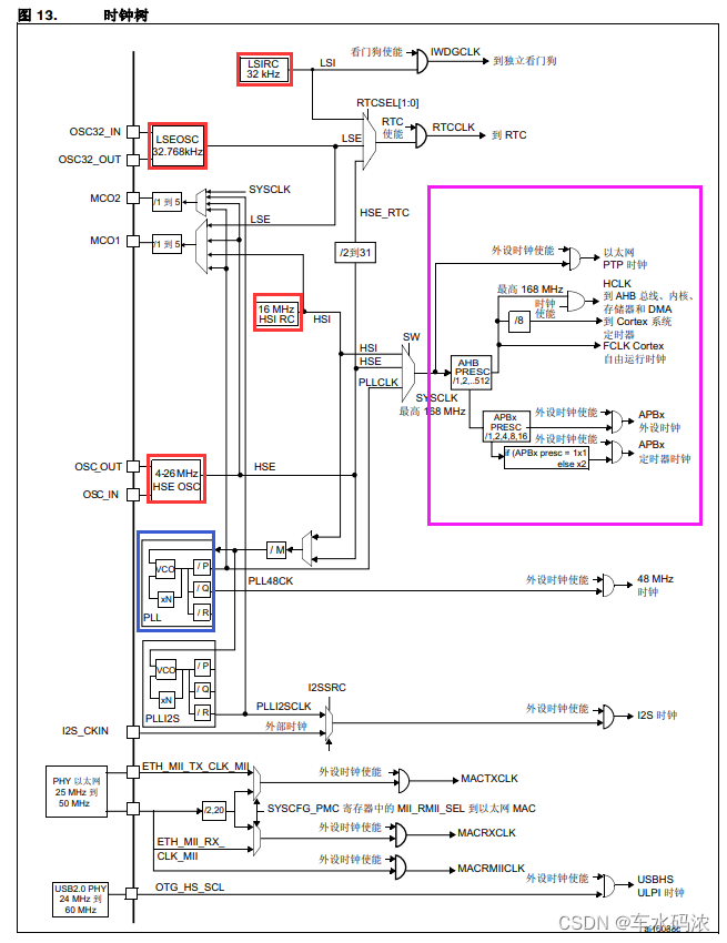
PLLHorloge de sortie pour = PLLSaisissez l'horloge X PLLN / PLLM / PLLP
168M = 8M X 336 / 8 / 2
4.Oui.keil5 L'horloge système du projet est configurée pour 168MHz
(1)Modifiersystem_stm32f4xx.cDe254D'accord
#define PLL_M 8
(2)Modifierstm32f4xx.hDe127D'accord
// Ce fichier est un fichier de propriétés en lecture seule , Pour trouver le fichier dans le système de fichiers ,Supprimer les attributs en lecture seule #define HSE_VALUE ((uint32_t)8000000) /*!< Value of the External oscillator in Hz */
Exercice:
Configurer la fréquence principale du système pour 168M
ModifierPLL, Réglage de la fréquence principale du système
#define PLL_N 336//168M #define PLL_N 432//216M Surfréquence #define PLL_N 168//84M Fréquence réduite
Fréquence d'horloge du bus système :
SYSCLKHorloge ------------ 168MHz HCLK/AHBBus ---------- 168MHz APB1Horloge -------------- 42MHz APB2Horloge -------------- 84MHz
__________________________________________________________________________________________________________________________________________________________
Bouton - poussoir
1.Regardez le schéma


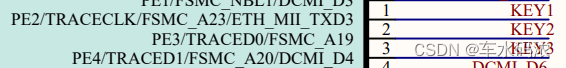
D'après le schéma:
Relâchez la clé. -------- Pin High
Appuyez sur la touche -------- Pin Low level
Pin correspondant à la clé :
S1 ----- PA0
S2 ----- PE2
S3 ----- PE3
S4 ----- PE4
Comment lire le niveau de la broche d'entrée
(1) Lire le registre des données d'entrée (IDR)Valeur du bit correspondant 1 ----- Haut niveau d'entrée 0 ----- Niveau d'entrée bas
(2) Opérations de segment PAin(0)==0 ----- Niveau d'entrée bas PAin(0)==1 ----- Haut niveau d'entrée
(3)Fonctions de bibliothèque uint8_t GPIO_ReadInputDataBit(GPIO_TypeDef* GPIOx, uint16_t GPIO_Pin); // Quel groupe, quel pied , Renvoie le niveau de cette broche
——————————————————————————————————————————————————————————————————————————————————————
Exercice:
Compléter la procédure d'essai pour les trois autres touches ,Utiliser séparément Registres Segment Jugement de la fonction bibliothèque
Réaliser une fonction :
Appuyez surS2,D2Lumière. Appuyez surS3,D3Lumière. Appuyez surS4,D4Lumière.
//key.c
#include <stm32f4xx.h>
#include <key.h>
void key_init(void)
{
    GPIO_InitTypeDef GPIO_InitStruct;

    //1.OuvertGPIOAL'horloge de
    RCC_AHB1PeriphClockCmd(RCC_AHB1Periph_GPIOA|RCC_AHB1Periph_GPIOE,ENABLE);

    //2.GPIOInitialisation PA0
    GPIO_InitStruct.GPIO_Mode = GPIO_Mode_IN;//Mode d'entrée
    GPIO_InitStruct.GPIO_PuPd = GPIO_PuPd_NOPULL;//Pas de descente
    GPIO_InitStruct.GPIO_Pin = GPIO_Pin_0;//PA0
    GPIO_Init(GPIOA,&GPIO_InitStruct);

    GPIO_InitStruct.GPIO_Pin = GPIO_Pin_2|GPIO_Pin_3|GPIO_Pin_4;//PE2 PE3 PE4
    GPIO_Init(GPIOE,&GPIO_InitStruct);
//main.c
#include <stm32f4xx.h>
#include <led.h>
#include <sys.h>
#include <key.h>

int main()
{
	int key_flag = 0;

	//Initialisation
	led_init();
	key_init();

	while(1){
		if(S1==0){
			//Délai d'élimination des secousses10ms
			delay(100);
			if(S1==0){
				// Événements clés réels
				if(key_flag==0){// Appuyez et ne relâchez pas
					D1 = ~D1;//Inverse
					key_flag = 1;
				}
			}
		}
		else{
			//Délai d'élimination des secousses10ms
			delay(100);
			if(S1){
				key_flag = 0;
			}
		}
	}

}
//lcd.c
include <stm32f4xx.h>
#include <led.h>

void delay(unsigned int ms)
{
	int i,j;

	for(i=0;i<ms;i++)
		for(j=0;j<5000;j++);
}

void led_init(void)
{
	GPIO_InitTypeDef GPIO_InitStruct;

	//1.OuvertGPIOE GPIOFL'horloge de
	RCC_AHB1PeriphClockCmd(RCC_AHB1Periph_GPIOE|RCC_AHB1Periph_GPIOF,ENABLE);

	//2.GPIOInitialisation PF9 PF10 PE13 PE14
	GPIO_InitStruct.GPIO_Mode = GPIO_Mode_OUT;//Mode de sortie
	GPIO_InitStruct.GPIO_OType = GPIO_OType_PP;//Sortie Push - pull
	GPIO_InitStruct.GPIO_Speed = GPIO_Speed_50MHz;//Haute vitesse
	GPIO_InitStruct.GPIO_PuPd = GPIO_PuPd_NOPULL;//Pas de descente
	GPIO_InitStruct.GPIO_Pin = GPIO_Pin_9|GPIO_Pin_10;//PF9 PF10
	GPIO_Init(GPIOF,&GPIO_InitStruct);

	GPIO_InitStruct.GPIO_Pin = GPIO_Pin_13|GPIO_Pin_14;//PE13 PE14
	GPIO_Init(GPIOE,&GPIO_InitStruct);

	//3.LEDFermeture par défaut
	GPIO_SetBits(GPIOF,GPIO_Pin_9|GPIO_Pin_10);
	GPIO_SetBits(GPIOE,GPIO_Pin_13|GPIO_Pin_14);
}
//lcd.h
#ifndef _LED_H_
#define _LED_H_

#define D1 PFout(9)
#define D2 PFout(10)
#define D3 PEout(13)
#define D4 PEout(14)

void delay(unsigned int ms);
void led_init(void);

#endif
//key.h
#ifndef _KEY_H_
#define _KEY_H_

#define S1 PAin(0)
#define S2 PEin(2)
#define S3 PEin(3)
#define S4 PEin(4)

void key_init(void);

#endif
//sys.h Ce fichier est défini par le système
#ifndef __SYS_H_
#define __SYS_H_
#include "stm32f4xx.h"

//IODéfinition de la macro d'exploitation du port
#define BITBAND(addr, bitnum) ((addr & 0xF0000000)+0x2000000+((addr &0xFFFFF)<<5)+(bitnum<<2))
#define MEM_ADDR(addr)  *((volatile unsigned long  *)(addr))
#define BIT_ADDR(addr, bitnum)   MEM_ADDR(BITBAND(addr, bitnum))
//IOCartographie des adresses de port
#define GPIOA_ODR_Addr    (GPIOA_BASE+20) //0x40020014
#define GPIOB_ODR_Addr    (GPIOB_BASE+20) //0x40020414
#define GPIOC_ODR_Addr    (GPIOC_BASE+20) //0x40020814
#define GPIOD_ODR_Addr    (GPIOD_BASE+20) //0x40020C14
#define GPIOE_ODR_Addr    (GPIOE_BASE+20) //0x40021014
#define GPIOF_ODR_Addr    (GPIOF_BASE+20) //0x40021414    20 = 0x14
#define GPIOG_ODR_Addr    (GPIOG_BASE+20) //0x40021814
#define GPIOH_ODR_Addr    (GPIOH_BASE+20) //0x40021C14
#define GPIOI_ODR_Addr    (GPIOI_BASE+20) //0x40022014

#define GPIOA_IDR_Addr    (GPIOA_BASE+16) //0x40020010    16 = 0x10
#define GPIOB_IDR_Addr    (GPIOB_BASE+16) //0x40020410
#define GPIOC_IDR_Addr    (GPIOC_BASE+16) //0x40020810
#define GPIOD_IDR_Addr    (GPIOD_BASE+16) //0x40020C10
#define GPIOE_IDR_Addr    (GPIOE_BASE+16) //0x40021010
#define GPIOF_IDR_Addr    (GPIOF_BASE+16) //0x40021410
#define GPIOG_IDR_Addr    (GPIOG_BASE+16) //0x40021810
#define GPIOH_IDR_Addr    (GPIOH_BASE+16) //0x40021C10
#define GPIOI_IDR_Addr    (GPIOI_BASE+16) //0x40022010

//IOOpérations portuaires,Pour un seulIOBouche!
//Assurez - vous quenValeur inférieure à16!
#define PAout(n)   BIT_ADDR(GPIOA_ODR_Addr,n)  //Produits
#define PAin(n)    BIT_ADDR(GPIOA_IDR_Addr,n)  //Entrée

#define PBout(n)   BIT_ADDR(GPIOB_ODR_Addr,n)  //Produits
#define PBin(n)    BIT_ADDR(GPIOB_IDR_Addr,n)  //Entrée

#define PCout(n)   BIT_ADDR(GPIOC_ODR_Addr,n)  //Produits
#define PCin(n)    BIT_ADDR(GPIOC_IDR_Addr,n)  //Entrée

#define PDout(n)   BIT_ADDR(GPIOD_ODR_Addr,n)  //Produits
#define PDin(n)    BIT_ADDR(GPIOD_IDR_Addr,n)  //Entrée

#define PEout(n)   BIT_ADDR(GPIOE_ODR_Addr,n)  //Produits
#define PEin(n)    BIT_ADDR(GPIOE_IDR_Addr,n)  //Entrée

#define PFout(n)   BIT_ADDR(GPIOF_ODR_Addr,n)  //Produits
#define PFin(n)    BIT_ADDR(GPIOF_IDR_Addr,n)  //Entrée

#define PGout(n)   BIT_ADDR(GPIOG_ODR_Addr,n)  //Produits
#define PGin(n)    BIT_ADDR(GPIOG_IDR_Addr,n)  //Entrée

#define PHout(n)   BIT_ADDR(GPIOH_ODR_Addr,n)  //Produits
#define PHin(n)    BIT_ADDR(GPIOH_IDR_Addr,n)  //Entrée

#define PIout(n)   BIT_ADDR(GPIOI_ODR_Addr,n)  //Produits
#define PIin(n)    BIT_ADDR(GPIOI_IDR_Addr,n)  //Entrée


#endif
3.Appuyez sur la touche pour éliminer les secousses————Délai d'élimination des secousses

Les programmes clés ci - dessus, qu'il y ait ou non un événement clé ,Ils vont tous occuperCPUPour juger, C'est ce qu'on appelle le scrutin ,Faible efficacité,CPU Offre un moyen plus efficace de --------- Interruption.
边栏推荐
- Special topic of binary tree -- acwing 1589 Building binary search tree
- LabVIEW为什么浮点数会丢失精度
- In the face of uncertainty, the role of supply chain
- 【AGC】如何解决事件分析数据本地和AGC面板中显示不一致的问题?
- 二叉树专题--AcWing 47. 二叉树中和为某一值的路径(前序遍历)
- 二叉树专题--AcWing 1497. 树的遍历(利用后、中序遍历,构建二叉树)
- Flick two open, realized a batch lookup join (with source code)
- [quick application] there are many words in the text component. How to solve the problem that the div style next to it will be stretched
- 华为AppLinking中统一链接的创建和使用
- JSP webshell free -- the basis of JSP
猜你喜欢


随机推荐
Open the encrypted SQLite method with sqlcipher
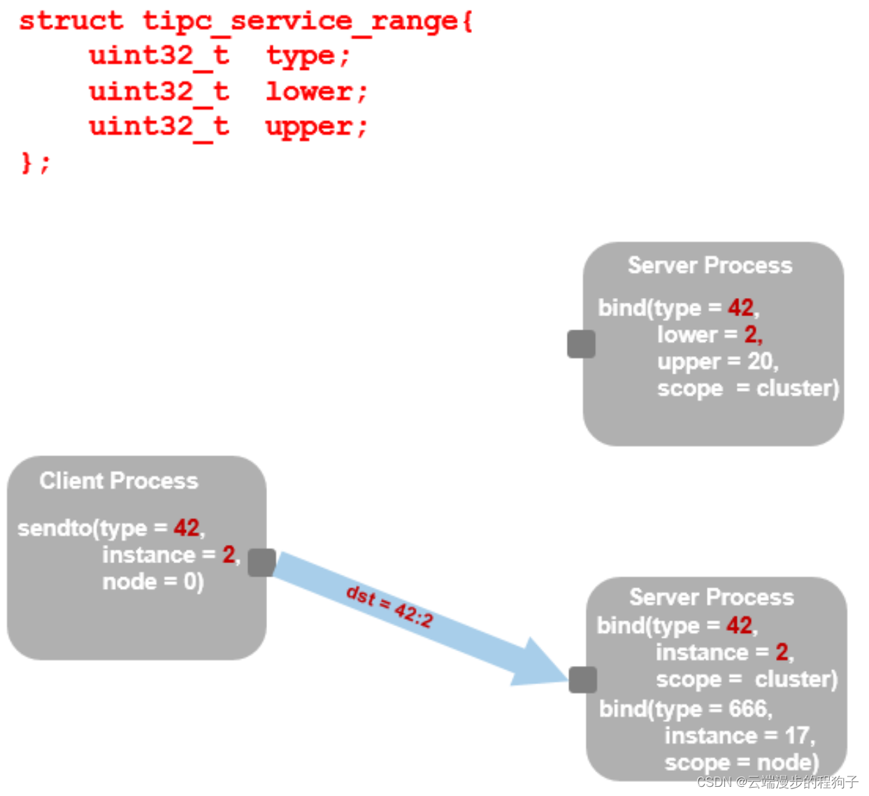
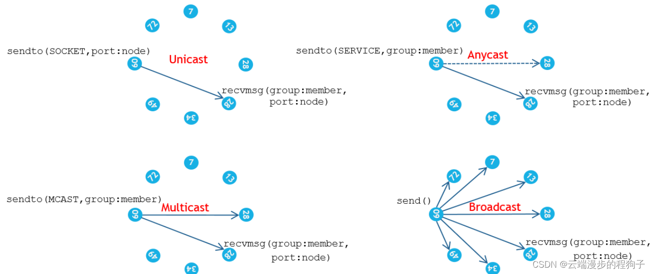
TIPC messaging3
Set the playback speed during the playback of UOB equipment
华为应用市场应用统计数据问题大揭秘
V2x SIM dataset (Shanghai Jiaotong University & New York University)
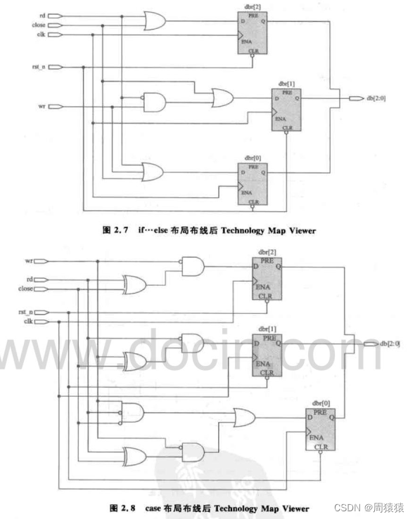
【深入浅出玩转FPGA学习2----设计技巧(基本语法)】
二叉树专题--AcWing 18. 重建二叉树(利用前、中序遍历,构建二叉树)
JSP webshell免杀——JSP的基础
快应用中实现自定义抽屉组件
Dialogue Wu Gang: why do I believe in the rise of "big country brands"?
Binary tree topic -- p1030 [noip2001 popularization group] find the first order
Overview of integrated learning
2. Hacking lab script off [detailed writeup]
[in simple terms, play with FPGA learning 3 ----- basic grammar]
In the face of uncertainty, the role of supply chain
[AGC] build service 3 - authentication service example
[SUCTF2018]followme
Hdu1228 a + B (map mapping)
The first white paper on agile practice in Chinese enterprises was released | complete download is attached
Point cloud projection picture