当前位置:网站首页>A detailed explanation of head pose estimation [collect good articles]
A detailed explanation of head pose estimation [collect good articles]
2022-07-07 04:35:00 【Oak China】
This article was first published in oakchina.cn,PDF download Address , The code download Address
author :OAK Members of the AI Club @ Ruan PY
In many applications , We need to know how the head tilts relative to the camera . for example , In virtual reality applications , You can use the pose of the head to render the correct view of the scene . In driver assistance , The camera on the car can observe the driver's face , Determine whether the driver is paying attention to the road through head pose estimation . Of course , People can also use gestures based on head posture to control hands-free applications .
In this article, we agree to use the following terms , In order to avoid confusion .
Postures : English is pose, Including position and posture .
Location : English is location .
picture : English is photo , Used in this article to refer to a photograph .
Images : English is image, In this paper, it is used in plane or coordinate system , for example image plane Refers to the image plane , image coordinate system Refers to the image coordinate system .
rotate : English is rotation .
translation : English is translation.
Transformation : English is transform .
Projection : English is project .
1、 What is pose estimation ?
In computer vision , The attitude of an object means that the object Relative to the camera The relative direction and position of . You can move objects relative to the camera , Or the camera moves relative to the object to change the pose .—— The two are equivalent for changing posture , Because the relationship between them is relative .
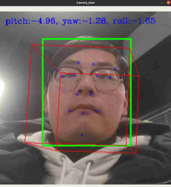
The pose estimation problem described in this paper is usually called “Perspective-n-Point” problem , Or in computer vision PnP problem .PnP The goal of the problem is to find the pose of an object , We need to have two conditions :
Conditions 1: There is a calibrated camera ;
Conditions 2: We know what's on an object n individual 3D Location of points locations And these 3D The corresponding point in the image 2D Projection .
2、 How to mathematically describe the motion of the camera
One 3D rigid body (rigid object) have only 2 Two types of motion relative to the camera .
The first one is : Translational motion (Translation). Translational motion refers to the camera moving from its current position location Its coordinates are (X, Y, Z) Move to the new coordinate position (X‘, Y’,Z‘). Translational motion has 3 A degree of freedom —— Go along X,Y,Z The direction of the three axes . Translational motion can be expressed as a vector t = (X’-X, Y’-Y, Z’-Z) To describe .
The second kind : Rotational motion (Rotation). It means to put the camera around X,Y,Z Shaft rotation . Rotational motion also has 3 A degree of freedom . There are many mathematical ways to describe rotational motion . Use Euler angle ( Rolling roll, Pitch pitch, Yaw yaw) describe , Use 3X3 Rotation matrix description of , Or use the direction and angle of rotation (directon of rotation and angle).
therefore ,3D In fact, the description of looking for the position and rotation of the object refers to the estimation of the position and rotation of the object 6 Number .
3、 What do you need for pose estimation ?
To calculate the of a rigid body in an image 3D Postures , You need the following information :
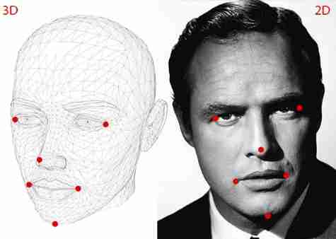
Information 1: Of several points 2D coordinate . You need a number of points in an image 2D(x, y) Location locations. In the case of the human face , You can choose : Canthus 、 Nose 、 Corners of the mouth, etc. . In this paper , We choose : Nose 、 chin 、 Left corner of eye 、 Right corner of the eye 、 Left corner of mouth 、 Right corner of mouth, etc 6 A little bit .
Information 2: And 2D Coordinate points correspond one-to-one 3D Location locations. You need 2D The characteristic point of 3D Location locations. You might think , You need the person in the picture 3D Model , In order to obtain 3D Location locations. Ideally, it does , But in reality , That's not the case . One 3D The model is really enough , But where did you get a head 3D The model ?—— We don't need a complete 3D Model ! We only need the of several points in an arbitrary reference system 3D Location 【Just need the 3D locations of a few
points in some arbitrary reference frame】. Be careful : there “ Some arbitrary reference system in some arbitrary reference frame” It's the point .
In this paper , We chose the following 3D spot :
(1) Nose (0.0, 0.0, 0.0).X、Y、Z Coordinates are 0.0 It means that this is the origin . Please think about it. , This is the origin of that coordinate system ? Is the camera coordinate system ? Or the world coordinate system ?
(2) chin (0.0, -330.0, -65.0).
(3) Left corner of eye (-225.0, 170.0, -135.0) .
(4) Right corner of the eye (225.0, 170.0, -135.0) .
(5) Left corner of mouth (-150.0, -150.0, -125.0) .
(6) Right corner of mouth (150.0, -150.0, -125.0) .
Be careful : The point above is “ Some arbitrary reference system / Coordinate system in some arbitrary reference frame / coordinate system” Medium , This coordinate system is called “ World coordinate system World Coordinates”. stay OpenCV In the document , Also known as “ Model coordinate system Model Coordinates”.
Information 3: Inside camera . As mentioned earlier , In this PnP In question , We assume that the camera has been calibrated . In other words , You need to know the focal length of the camera focal length、 The optical center of the image 、 Radial distortion parameters .—— therefore , You need to calibrate your camera . Of course , For those of us who like to be lazy , This job is too cumbersome . Is there any way to be lazy ? It does !
Because no precise 3D Model , We are already in an approximate state . We can further approximate :(1) We can use The image center The approximate Optical center ;(2) With images Pixel width The approximate The focal length of the camera ;(3) It is assumed that there is no radial distortion .
4、 How does the pose estimation algorithm work ?
There are many pose estimation algorithms , The most famous can be traced back to 1841 year . The detailed discussion of this algorithm is beyond the scope of this paper . Here is only a brief core idea .
The pose estimation PnP The problem involves 3 A coordinate system .(1) World coordinate system . Of the various facial features given earlier 3D Coordinates are in the world coordinate system ;(2) If we know the rotation matrix R Vector of peaceful shift t , We can In the world coordinate system 3D spot “ Transformation Transform” To In the camera coordinate system 3D spot .(3) Use the camera internal parameter matrix , The camera coordinates can be 3D Points can be projected onto the image plane image plane, Even if the image coordinate system image coordinate system.
The whole problem is 3 Play in a coordinate system : 3D The world coordinate system of World coordiantes、3D Camera coordinate system Camera coordinates、2D Image coordinate system Image coordinates.
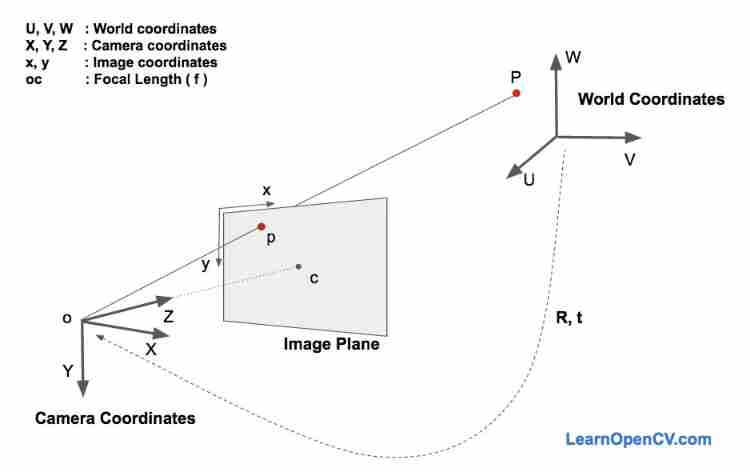
below , Let's go deep into the image generation equation , To understand how the above three coordinate systems work .
In the above picture , Lower left corner O It's the center of the camera , The middle plane Image Plane It's like a plane , We are interested in finding out “ take 3D spot P Project to the midpoint of the image plane p The equation of ”.
First , We assume that we already know that it is located in the world coordinate system 3D spot P The location of (U,V,W ), If we know the coordinate system of the camera relative to the coordinate system of the world R Vector of peaceful shift t, Through the following equation , You can calculate the point P Position in camera coordinate system (X, Y, Z).

Put the above equation (1) an , We get the following form :

If you have studied linear algebra , Should know : For the above equation , If you know the correspondence of a sufficient number of points 【(X, Y, Z ) and (U,V,W ) The correspondence between 】, So the equation above (2) Even a system of linear equations , among , rij and (tx, ty, tz) Is the unknown . Using the knowledge of Linear Algebra , Can solve these unknowns .
As will be described in the following chapters , We know (X, Y, Z) Only on an unknown scale 【 Or say (X, Y, Z) Determined only by an unknown scale 】, So we don't have a simple linear system .
5、 Direct linear transformation (Direct Linear Transform)
We already know that 3D Model 【 World coordinate system 】 Many points in 【 That is to say (U,V,W )】, however , We don't know (X, Y, Z) . That's all we know 3D Point to point 2D spot 【 In image plane Image Plane in 】 The location of 【 That is to say (x, y) 】. Without considering the distortion parameters , Like the midpoint of the plane p Coordinates of (x,y) By the following equation (3) give .

here , fx and fy They are focal length f stay x Axis and y Length in the axial direction .(cx, cy) Is the optical center of the camera . If the radial distortion parameter is considered , Then things will get a little more complicated . therefore , For the sake of simplicity , We ignore the radial distortion .
Equation (3) Medium s What is it? ? It is an unknown scale factor scale factor . Because we don't have a dot in the image depth Information , So this s Must exist in the equation . introduce s It's to show that : chart 2 Medium ray O-P Any point on the , No matter far or near , In the image plane Image Plane It's all the same point on the p .
in other words : If we take any point in the world coordinate system P And the center point of the camera coordinate system O Connect , ray O-P And image plane Image Plane The point of intersection is the point P The image point on the image plane p, Any point on the ray P , Will produce the same image point on the image plane p .
Now? , The above discussion has put the equation (2) It's complicated . Because this is not what we are familiar with 、 One that can be solved “ Good linear equation ” 了 . Our equation looks more like the following form .

however , Fortunately, , The equation in the above form , You can use some “ Algebraic magic ” To solve —— Direct linear transformation (DLT). When you find the equation of a problem “ It's almost linear , However, due to the existence of unknown scale factors , The equation is not completely linear ”, Then you can use DLT Method to solve .
6、 Levenberg - Marquardt optimization algorithm ( Levenberg-Marquardt Optimization)
For the following reasons , As stated earlier DLT The solution is not very accurate . First of all : Rotating vector R Yes 3 A degree of freedom , however DLT The matrix descriptions used in the scheme are 9 Number ,DLT There are no measures in the plan “ After forced estimation 3X3 The matrix of becomes a rotation matrix ”. what's more :DLT The plan doesn't have “ The correct objective function ”. You bet , We want to minimize “ Reprojection error reprojection error”, As will be discussed below .
For the equation (2) And the equation (3), If we know the correct posture ( matrix R Sum vector t), By way of 3D Point projection to 2D Like in a plane , We can predict 3D Facial point 2D The position of the point in the image locations . In other words , If we knew R and t, For each of these 3D spot P, We can all find the right point on the image plane p.
We also know 2D Facial feature points 【 adopt Dlib Or click it manually 】. We can observe the projected 3D Point and 2D The distance between facial features . When the pose estimation result is accurate , Projected onto the image plane Image Plane Medium 3D Point will be with 2D Facial feature points are almost perfectly aligned . however , When the pose estimation is inaccurate , We can calculate “ Reprojection error reprojection error” —— Projected by 3D Point and 2D Sum of squares of distances between facial feature points .
Postures (R and t) The approximate estimate of can be used DLT programme . improvement DLT A simple solution is random “ slight ” change attitude (R and t), And check whether the re projection error is reduced . If it does decrease , Let's use the new estimation results . We can constantly disturb R and t To find a better estimate . Although this method can work , But it's slow . Can prove that , There are some basic methods that can be changed iteratively R and t Value , So as to reduce the re projection error .—— One of them is the so-called “ Levenberg - Marquardt optimization algorithm ”.
7、OpenCV Pose estimation in
stay OpenCV in , There are two methods for pose estimation API: solvePnP and solvePnPRansac .
solvePnP Several attitude estimation algorithms are implemented , Different algorithms can be selected using parameters . By default , It uses signs SOLVEPNP_ITERATIVE, It's essentially DLT Solution , Then lewenberg - Optimization by Marquardt algorithm .SOLVEPNP_P3P Use only 3 A point to calculate the pose , And should only be used in solvePnPRansac When using . stay OpenCV 3 in , Introduced SOLVEPNP_DLS and SOLVEPNP_UPNP Two new methods . About SOLVEPNP_UPNP The interesting thing is , It's estimating the pose is , Also try to estimate the internal parameters of the camera .
solvePnPRansac Medium “Ransac” yes “ Random sampling consistency algorithm Random Sample Consensus” It means . introduce Ransac For the robustness of pose estimation . When you suspect that some data points are noise data , Use RANSAC It's very useful .
8、 Examples
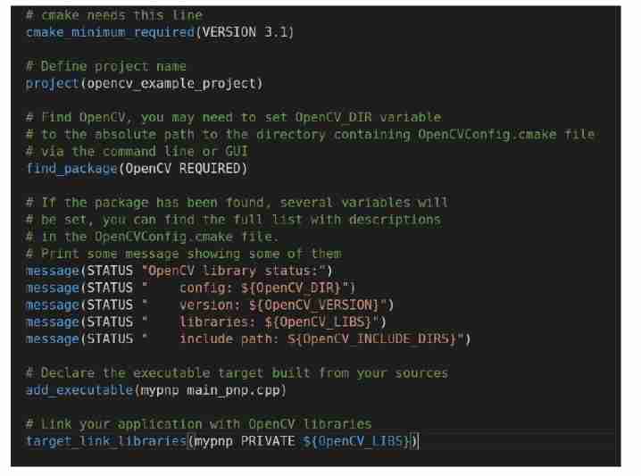
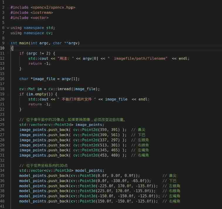
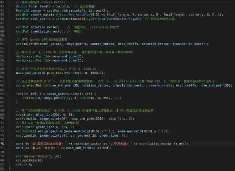
CMakeLists.txt file :
Picture file :

Source code :
OAK China | track AI New developments in technology and products
official account | OAK Visual artificial intelligence development
spot 「 here 」 Add wechat friends ( Remarks )
stamp 「+ Focus on 」 Get the latest information
边栏推荐
- C#使用西门子S7 协议读写PLC DB块
- Surpassing postman, the new generation of domestic debugging tool apifox is elegant enough to use
- Zero knowledge private application platform aleo (1) what is aleo
- Easycvr cannot be played using webrtc. How to solve it?
- Station B boss used my world to create convolutional neural network, Lecun forwarding! Burst the liver for 6 months, playing more than one million
- 图灵诞辰110周年,智能机器预言成真了吗?
- [team learning] [34 issues] scratch (Level 2)
- Why does WordPress open so slowly?
- 1.19.11. SQL client, start SQL client, execute SQL query, environment configuration file, restart policy, user-defined functions, constructor parameters
- 广告归因:买量如何做价值衡量?
猜你喜欢
acwing 843. n-皇后问题

接口自动化测试实践指导(中):接口测试场景有哪些
How do test / development programmers get promoted? From nothing, from thin to thick

C#使用西门子S7 协议读写PLC DB块
How to solve the problem of adding RTSP device to easycvr cluster version and prompting server ID error?

测试/开发程序员怎么升职?从无到有,从薄变厚.......

EasyCVR集群版本添加RTSP设备提示服务器ID错误,该如何解决?
![[team learning] [34 issues] scratch (Level 2)](/img/29/8383d753eedcffd874bc3f0194152a.jpg)
[team learning] [34 issues] scratch (Level 2)
Break the memory wall with CPU scheme? Learn from PayPal to expand the capacity of aoteng, and the volume of missed fraud transactions can be reduced to 1/30

buildroot的根文件系统提示“depmod:applt not found”
随机推荐
The worse the AI performance, the higher the bonus? Doctor of New York University offered a reward for the task of making the big model perform poorly
计数排序基础思路
数学分析_笔记_第10章:含参变量积分
Fix the problem that the highlight effect of the main menu disappears when the easycvr Video Square is clicked and played
[on automation experience] the growth path of automated testing
树与图的深度优先遍历模版原理
用CPU方案打破内存墙?学PayPal堆傲腾扩容量,漏查欺诈交易量可降至1/30
軟件測試之網站測試如何進行?測試小攻略走起!
深耕开发者生态,加速AI产业创新发展 英特尔携众多合作伙伴共聚
[team learning] [34 sessions] Alibaba cloud Tianchi online programming training camp
赠票速抢|行业大咖纵论软件的质量与效能 QECon大会来啦
See Gardenia minor
Station B boss used my world to create convolutional neural network, Lecun forwarding! Burst the liver for 6 months, playing more than one million
Break the memory wall with CPU scheme? Learn from PayPal to expand the capacity of aoteng, and the volume of missed fraud transactions can be reduced to 1/30
Nanopineo use development process record
Golang calculates constellations and signs based on birthdays
EasyCVR平台接入RTMP协议,接口调用提示获取录像错误该如何解决?
2022 electrician cup a question high proportion wind power system energy storage operation and configuration analysis ideas
科兴与香港大学临床试验中心研究团队和香港港怡医院合作,在中国香港启动奥密克戎特异性灭活疫苗加强剂临床试验
GPT-3当一作自己研究自己,已投稿,在线蹲一个同行评议