当前位置:网站首页>2. GPIO related operations
2. GPIO related operations
2022-07-06 03:25:00 【rou252051452】
1、 summary
STM32 Of GPIO Operations are classified into RTT Of pin In the device , In this paper, the reference RTT About PIN Relevant instructions of the equipment (RT-Thread Document center ) Write and test . It involves the following aspects
- GPIO Pin acquisition
- GPIO Output control
- GPIO Input to get
- GPIO External interrupt implementation of
2、 Acquisition of pin number
RT-Thread The pin number provided should be distinguished from the pin number of the chip , They are not the same concept , The pin number is determined by PIN Device driver definition , Related to specific chips . The official provided 3 There are three ways to get the pin number :
- Use API
- Use a macro to define
- View driver file
2.1 Drive file update
API Get the method through the function rt_pin_get Realization , The procedure is as follows
rt_base_t rt_pin_get(const char *name)
{
    RT_ASSERT(_hw_pin.ops != RT_NULL);
    RT_ASSERT(name[0] == 'P');

    if(_hw_pin.ops->pin_get == RT_NULL)
    {
        return -RT_ENOSYS;
    }

    return _hw_pin.ops->pin_get(name);
}
Check the initialization phase pair _hw_pin->ops The settings of are as follows
const static struct rt_pin_ops _stm32_pin_ops =
{
    stm32_pin_mode,
    stm32_pin_write,
    stm32_pin_read,
    stm32_pin_attach_irq,
    stm32_pin_dettach_irq,
    stm32_pin_irq_enable,
};
struct rt_pin_ops
{
void (*pin_mode)(struct rt_device *device, rt_base_t pin, rt_base_t mode);
void (*pin_write)(struct rt_device *device, rt_base_t pin, rt_base_t value);
int (*pin_read)(struct rt_device *device, rt_base_t pin);
rt_err_t (*pin_attach_irq)(struct rt_device *device, rt_int32_t pin,
rt_uint32_t mode, void (*hdr)(void *args), void *args);
rt_err_t (*pin_detach_irq)(struct rt_device *device, rt_int32_t pin);
rt_err_t (*pin_irq_enable)(struct rt_device *device, rt_base_t pin, rt_uint32_t enabled);
rt_base_t (*pin_get)(const char *name);
};Above ops Not in China pin_get How to implement the function , So we need to update drv_gpio Driver file . Use C:\RT-ThreadStudio\repo\Extract\Board_Support_Packages\RealThread\STM32H750-RT-ART-Pi\1.2.1\libraries\drivers Of drv_gpio.c Replace the driver file in the directory , Synchronize updates .h file . Check the updated content as follows
const static struct rt_pin_ops _stm32_pin_ops =
{
    stm32_pin_mode,
    stm32_pin_write,
    stm32_pin_read,
    stm32_pin_attach_irq,
    stm32_pin_dettach_irq,
    stm32_pin_irq_enable,
    stm32_pin_get,
};
2.2 Realization way
2.2.1 Use API
static rt_uint32_t reset_pin = 0;
reset_pin = rt_pin_get("PF.9");
rt_base_t rt_pin_get(const char *name)
{
RT_ASSERT(_hw_pin.ops != RT_NULL);
RT_ASSERT(name[0] == 'P');
if(_hw_pin.ops->pin_get == RT_NULL)
{
return -RT_ENOSYS;
}
return _hw_pin.ops->pin_get(name);
}As shown above ,rt_pin_get First, check whether the input string is a letter P start , The function finally called is _hw_pin.ops->pin_get(name); The contents are as follows :
static rt_base_t stm32_pin_get(const char *name)
{
    rt_base_t pin = 0;
    int hw_port_num, hw_pin_num = 0;
    int i, name_len;

    name_len = rt_strlen(name);

    if ((name_len < 4) || (name_len >= 6))          // Perform string length verification PA.0   PA.15   The shortest 4, The longest 5
    {
        return -RT_EINVAL;
    }
    if ((name[0] != 'P') || (name[2] != '.'))      // The first string must be P    The third must be .
    {
        return -RT_EINVAL;
    }

    if ((name[1] >= 'A') && (name[1] <= 'Z'))      // The port range is A-Z
    {
        hw_port_num = (int)(name[1] - 'A');        // Port number calculation ,A-Z Convert to 0-25
    }
    else
    {
        return -RT_EINVAL;
    }

    for (i = 3; i < name_len; i++)                // According to the... Of the string 4 Number conversion PA.0=0  PA.15 = 15
    {
        hw_pin_num *= 10;
        hw_pin_num += name[i] - '0';
    }

    pin = PIN_NUM(hw_port_num, hw_pin_num);        // Process the last pin number

    return pin;
}
Finally, call the macro definition as follows to obtain the pin number
#define PIN_NUM(port, no) (((((port) & 0xFu) << 4) | ((no) & 0xFu)))The calculation results are shown in the following table , follow-up IO And so on
| name | port | no | result | name | port | no | result |
| PA.0 | 0 | 0 | 0 | PC.0 | 2 | 0 | 32 |
| PA.1 | 0 | 1 | 1 | PC.1 | 2 | 1 | 33 |
| PA.2 | 0 | 2 | 2 | PC.2 | 2 | 2 | 34 |
| PA.3 | 0 | 3 | 3 | PC.3 | 2 | 3 | 35 |
| PA.4 | 0 | 4 | 4 | PC.4 | 2 | 4 | 36 |
| PA.5 | 0 | 5 | 5 | PC.5 | 2 | 5 | 37 |
| PA.6 | 0 | 6 | 6 | PC.6 | 2 | 6 | 38 |
| PA.7 | 0 | 7 | 7 | PC.7 | 2 | 7 | 39 |
| PA.8 | 0 | 8 | 8 | PC.8 | 2 | 8 | 40 |
| PA.9 | 0 | 9 | 9 | PC.9 | 2 | 9 | 41 |
| PA.10 | 0 | 10 | 10 | PC.10 | 2 | 10 | 42 |
| PA.11 | 0 | 11 | 11 | PC.11 | 2 | 11 | 43 |
| PA.12 | 0 | 12 | 12 | PC.12 | 2 | 12 | 44 |
| PA.13 | 0 | 13 | 13 | PC.13 | 2 | 13 | 45 |
| PA.14 | 0 | 14 | 14 | PC.14 | 2 | 14 | 46 |
| PA.15 | 0 | 15 | 15 | PC.15 | 2 | 15 | 47 |
| PB.0 | 1 | 0 | 16 | PD.0 | 3 | 0 | 48 |
| PB.1 | 1 | 1 | 17 | PD.1 | 3 | 1 | 49 |
| PB.2 | 1 | 2 | 18 | PD.2 | 3 | 2 | 50 |
| PB.3 | 1 | 3 | 19 | PD.3 | 3 | 3 | 51 |
| PB.4 | 1 | 4 | 20 | PD.4 | 3 | 4 | 52 |
| PB.5 | 1 | 5 | 21 | PD.5 | 3 | 5 | 53 |
| PB.6 | 1 | 6 | 22 | PD.6 | 3 | 6 | 54 |
| PB.7 | 1 | 7 | 23 | PD.7 | 3 | 7 | 55 |
| PB.8 | 1 | 8 | 24 | PD.8 | 3 | 8 | 56 |
| PB.9 | 1 | 9 | 25 | PD.9 | 3 | 9 | 57 |
| PB.10 | 1 | 10 | 26 | PD.10 | 3 | 10 | 58 |
| PB.11 | 1 | 11 | 27 | PD.11 | 3 | 11 | 59 |
| PB.12 | 1 | 12 | 28 | PD.12 | 3 | 12 | 60 |
| PB.13 | 1 | 13 | 29 | PD.13 | 3 | 13 | 61 |
| PB.14 | 1 | 14 | 30 | PD.14 | 3 | 14 | 62 |
| PB.15 | 1 | 15 | 31 | PD.15 | 3 | 15 | 63 |
2.2.2 Use a macro to define
#define LED0_PIN GET_PIN(F, 9)#define __STM32_PORT(port) GPIO##port##_BASE
#if defined(SOC_SERIES_STM32MP1)
#define GET_PIN(PORTx,PIN) (GPIO##PORTx == GPIOZ) ? (176 + PIN) : ((rt_base_t)((16 * ( ((rt_base_t)__STM32_PORT(PORTx) - (rt_base_t)GPIOA_BASE)/(0x1000UL) )) + PIN))
#else
#define GET_PIN(PORTx,PIN) (rt_base_t)((16 * ( ((rt_base_t)__STM32_PORT(PORTx) - (rt_base_t)GPIOA_BASE)/(0x0400UL) )) + PIN)
#endif| Macro definition | PORTx | 16 * ( ((rt_base_t)__STM32_PORT(PORTx) - (rt_base_t)GPIOA_BASE)/(0x0400UL) ) | PIN | result | |
| GET_PIN(A, 0) | GPIOA_BASE | D3_AHB1PERIPH_BASE + 0x0000UL | 0 | 0 | 0 |
| GET_PIN(A, 1) | GPIOA_BASE | D3_AHB1PERIPH_BASE + 0x0000UL | 0 | 0 | 0 |
| GET_PIN(A, 2) | GPIOA_BASE | D3_AHB1PERIPH_BASE + 0x0000UL | 0 | 0 | 0 |
| GET_PIN(A, 3) | GPIOA_BASE | D3_AHB1PERIPH_BASE + 0x0000UL | 0 | 0 | 0 |
| GET_PIN(B, 0) | GPIOB_BASE | D3_AHB1PERIPH_BASE + 0x0400UL | 1 | 0 | 16 |
| GET_PIN(B, 1) | GPIOB_BASE | D3_AHB1PERIPH_BASE + 0x0400UL | 1 | 1 | 17 |
| GET_PIN(B, 2) | GPIOB_BASE | D3_AHB1PERIPH_BASE + 0x0400UL | 1 | 2 | 18 |
Results and API The implementation results are the same .
2.2.3 View driver file
This method updates the driver file drv_gpio There is no official document description of the view drive mode , There is no detailed description here .
3、GPIO Output control
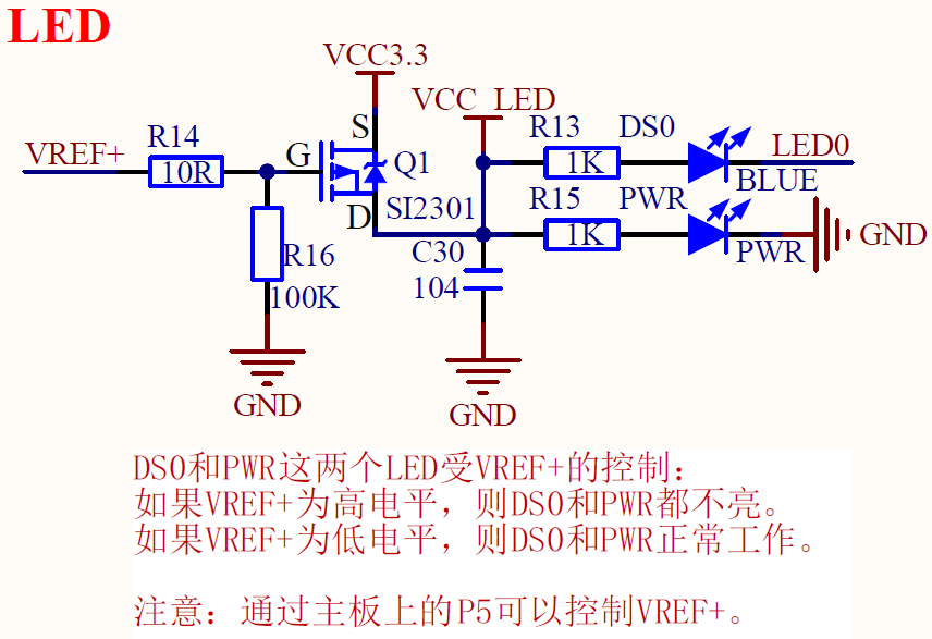
We control the LED Light to verify GPIO The output function of .
#include "rtthread.h"
#include "rtdevice.h"
#include "board.h"
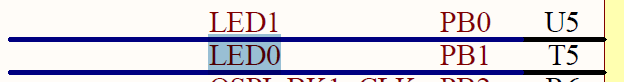
#define LED0 GET_PIN(B, 0)
void example_gpio()
{
rt_pin_mode(LED0,PIN_MODE_OUTPUT); // Set the pin to output
rt_pin_write(LED0,PIN_LOW);
}
MSH_CMD_EXPORT(example_gpio, example_gpio)
4、GPIO Input control
Control the core board by on-board buttons LED The light is on and off , Press and the rear light will be on , The light goes out after loosening
![]()
#include "rtthread.h"
#include "rtdevice.h"
#include "board.h"

#define LED0    GET_PIN(B, 0)

void example_gpio()
{
    static rt_uint32_t key = 0;

    rt_pin_mode(LED0,PIN_MODE_OUTPUT);          // Set the pin to output
    rt_pin_write(LED0,PIN_LOW);

    key = rt_pin_get("PA.0");                   // Get pin number
    rt_pin_mode(key,PIN_MODE_INPUT);            // Set the pin as input
    while(1)
    {
        if(rt_pin_read(key) == PIN_HIGH)        // Read input status
        {
            rt_pin_write(LED0,PIN_LOW);
        }
        else
        {
            rt_pin_write(LED0,PIN_HIGH);
        }
        rt_thread_mdelay(1000);
    }
}
MSH_CMD_EXPORT(example_gpio, example_gpio)
5、GPIO interrupt
Control the core board by on-board buttons LED The light is on and off , Press to interrupt the rising edge , Light on . The falling edge is interrupted after loosening , The light goes out
6、 Detailed explanation of driving process
6.1 Mode setting
The function called by mode setting is rt_pin_mode, The function finally called is ops->pin_mode, by drv_gpio.c Medium stm32_pin_mode function , The details are as follows
static void stm32_pin_mode(rt_device_t dev, rt_base_t pin, rt_base_t mode)
{
    GPIO_InitTypeDef GPIO_InitStruct;

    // Identify whether the port number is legal
    if (PIN_PORT(pin) >= PIN_STPORT_MAX)
    {
        return;
    }

    /*
         Conduct GPIO Initialize the relevant assignment of the structure
         The default configuration is push-pull output , High speed , No up and down
    */
    GPIO_InitStruct.Pin = PIN_STPIN(pin);
    GPIO_InitStruct.Mode = GPIO_MODE_OUTPUT_PP;
    GPIO_InitStruct.Pull = GPIO_NOPULL;
    GPIO_InitStruct.Speed = GPIO_SPEED_FREQ_HIGH;

    /*
         Modify relevant contents according to the input mode parameters .
    */
    if (mode == PIN_MODE_OUTPUT)
    {
        /* output setting */
        GPIO_InitStruct.Mode = GPIO_MODE_OUTPUT_PP;
        GPIO_InitStruct.Pull = GPIO_NOPULL;
    }
    else if (mode == PIN_MODE_INPUT)
    {
        /* input setting: not pull. */
        GPIO_InitStruct.Mode = GPIO_MODE_INPUT;
        GPIO_InitStruct.Pull = GPIO_NOPULL;
    }
    else if (mode == PIN_MODE_INPUT_PULLUP)
    {
        /* input setting: pull up. */
        GPIO_InitStruct.Mode = GPIO_MODE_INPUT;
        GPIO_InitStruct.Pull = GPIO_PULLUP;
    }
    else if (mode == PIN_MODE_INPUT_PULLDOWN)
    {
        /* input setting: pull down. */
        GPIO_InitStruct.Mode = GPIO_MODE_INPUT;
        GPIO_InitStruct.Pull = GPIO_PULLDOWN;
    }
    else if (mode == PIN_MODE_OUTPUT_OD)
    {
        /* output setting: od. */
        GPIO_InitStruct.Mode = GPIO_MODE_OUTPUT_OD;
        GPIO_InitStruct.Pull = GPIO_NOPULL;
    }

    /*
         Conduct GPIO initialization , According to the macro definition PIN_STPORT Identify GPIOx The address of
    */
    HAL_GPIO_Init(PIN_STPORT(pin), &GPIO_InitStruct);
}
6.2 Output level control
The function called by the output level is rt_pin_write, The function finally called is ops->pin_write, by drv_gpio.c Medium stm32_pin_write function , The details are as follows
static void stm32_pin_write(rt_device_t dev, rt_base_t pin, rt_base_t value)
{
    GPIO_TypeDef *gpio_port;
    uint16_t gpio_pin;

    // Convert the pin serial number to port and pin Information , call HAL Library function for output
    if (PIN_PORT(pin) < PIN_STPORT_MAX)
    {
        gpio_port = PIN_STPORT(pin);
        gpio_pin = PIN_STPIN(pin);

        HAL_GPIO_WritePin(gpio_port, gpio_pin, (GPIO_PinState)value);
    }
}
6.3 Input level acquisition
The function called by the input level acquisition is rt_pin_read, The function finally called is ops->pin_read, by drv_gpio.c Medium stm32_pin_read function , The details are as follows
static int stm32_pin_read(rt_device_t dev, rt_base_t pin)
{
    GPIO_TypeDef *gpio_port;
    uint16_t gpio_pin;
    int value = PIN_LOW;
     // Convert the pin serial number to port and pin Information , call HAL Library function to obtain input information
    if (PIN_PORT(pin) < PIN_STPORT_MAX)
    {
        gpio_port = PIN_STPORT(pin);
        gpio_pin = PIN_STPIN(pin);
        value = HAL_GPIO_ReadPin(gpio_port, gpio_pin);
    }

    return value;
}
6.4 Binding pin interrupt callback function
The binding interrupt function calls rt_pin_attach_irq, The function finally called is ops->pin_attach_irq, by drv_gpio.c Medium stm32_pin_attach_irq function , The details are as follows
It just went on rtt Next pin The interrupt pin mode of the device and the assignment of the interrupt callback function , No substantive STM32 The bottom of the HAL Library Configuration .
static rt_err_t stm32_pin_attach_irq(struct rt_device *device, rt_int32_t pin,
                                     rt_uint32_t mode, void (*hdr)(void *args), void *args)
{
    rt_base_t level;
    rt_int32_t irqindex = -1;

    // Identify whether the port is correct
    if (PIN_PORT(pin) >= PIN_STPORT_MAX)
    {
        return -RT_ENOSYS;
    }

    // Identify the interrupt source   0-15
    irqindex = bit2bitno(PIN_STPIN(pin));
    if (irqindex < 0 || irqindex >= ITEM_NUM(pin_irq_map))
    {
        return RT_ENOSYS;
    }

    level = rt_hw_interrupt_disable();
    if (pin_irq_hdr_tab[irqindex].pin == pin &&
        pin_irq_hdr_tab[irqindex].hdr == hdr &&
        pin_irq_hdr_tab[irqindex].mode == mode &&
        pin_irq_hdr_tab[irqindex].args == args)
    {
        rt_hw_interrupt_enable(level);
        return RT_EOK;
    }
    if (pin_irq_hdr_tab[irqindex].pin != -1)
    {
        rt_hw_interrupt_enable(level);
        return RT_EBUSY;
    }
    pin_irq_hdr_tab[irqindex].pin = pin;
    pin_irq_hdr_tab[irqindex].hdr = hdr;
    pin_irq_hdr_tab[irqindex].mode = mode;
    pin_irq_hdr_tab[irqindex].args = args;
    rt_hw_interrupt_enable(level);

    return RT_EOK;
}
Concrete HAL The bottom driver of the library is configured in rt_pin_irq_enable Function , The final calling function of this function is stm32_pin_irq_enable The contents are as follows :
static rt_err_t stm32_pin_irq_enable(struct rt_device *device, rt_base_t pin,
                                     rt_uint32_t enabled)
{
    const struct pin_irq_map *irqmap;
    rt_base_t level;
    rt_int32_t irqindex = -1;
    GPIO_InitTypeDef GPIO_InitStruct;

    // distinguish IO Is it legal
    if (PIN_PORT(pin) >= PIN_STPORT_MAX)
    {
        return -RT_ENOSYS;
    }

    // To interrupt , Carry out the configuration of yes .
    if (enabled == PIN_IRQ_ENABLE)
    {
        // Get pin serial number
        irqindex = bit2bitno(PIN_STPIN(pin));
        if (irqindex < 0 || irqindex >= ITEM_NUM(pin_irq_map))
        {
            return RT_ENOSYS;
        }

        level = rt_hw_interrupt_disable();

        //pin_irq_hdr_tab The content is in stm32_pin_attach_irq Assignment was made .
        if (pin_irq_hdr_tab[irqindex].pin == -1)
        {
            rt_hw_interrupt_enable(level);
            return RT_ENOSYS;
        }

        // Get the interrupt sequence number according to the pin    EXTI0_IRQn-EXTI4_IRQn or EXTI9_5_IRQn
        irqmap = &pin_irq_map[irqindex];

        // To configure GPIO Initialize structure
        /* Configure GPIO_InitStructure */
        GPIO_InitStruct.Pin = PIN_STPIN(pin);
        GPIO_InitStruct.Speed = GPIO_SPEED_FREQ_HIGH;
        switch (pin_irq_hdr_tab[irqindex].mode)
        {
        case PIN_IRQ_MODE_RISING:
            GPIO_InitStruct.Pull = GPIO_PULLDOWN;
            GPIO_InitStruct.Mode = GPIO_MODE_IT_RISING;
            break;
        case PIN_IRQ_MODE_FALLING:
            GPIO_InitStruct.Pull = GPIO_PULLUP;
            GPIO_InitStruct.Mode = GPIO_MODE_IT_FALLING;
            break;
        case PIN_IRQ_MODE_RISING_FALLING:
            GPIO_InitStruct.Pull = GPIO_NOPULL;
            GPIO_InitStruct.Mode = GPIO_MODE_IT_RISING_FALLING;
            break;
        }
        HAL_GPIO_Init(PIN_STPORT(pin), &GPIO_InitStruct);

        // Set interrupt priority , To interrupt
        HAL_NVIC_SetPriority(irqmap->irqno, 5, 0);
        HAL_NVIC_EnableIRQ(irqmap->irqno);
        pin_irq_enable_mask |= irqmap->pinbit;

        rt_hw_interrupt_enable(level);
    }
    // No interruptions
    else if (enabled == PIN_IRQ_DISABLE)
    {
        irqmap = get_pin_irq_map(PIN_STPIN(pin));
        if (irqmap == RT_NULL)
        {
            return RT_ENOSYS;
        }

        level = rt_hw_interrupt_disable();
        // Reset GPIO
        HAL_GPIO_DeInit(PIN_STPORT(pin), PIN_STPIN(pin));

        pin_irq_enable_mask &= ~irqmap->pinbit;

        if ((irqmap->pinbit >= GPIO_PIN_5) && (irqmap->pinbit <= GPIO_PIN_9))
        {
            if (!(pin_irq_enable_mask & (GPIO_PIN_5 | GPIO_PIN_6 | GPIO_PIN_7 | GPIO_PIN_8 | GPIO_PIN_9)))
            {
                HAL_NVIC_DisableIRQ(irqmap->irqno);
            }
        }
        else if ((irqmap->pinbit >= GPIO_PIN_10) && (irqmap->pinbit <= GPIO_PIN_15))
        {
            if (!(pin_irq_enable_mask & (GPIO_PIN_10 | GPIO_PIN_11 | GPIO_PIN_12 | GPIO_PIN_13 | GPIO_PIN_14 | GPIO_PIN_15)))
            {
                HAL_NVIC_DisableIRQ(irqmap->irqno);
            }
        }
        else
        {
            HAL_NVIC_DisableIRQ(irqmap->irqno);
        }

        rt_hw_interrupt_enable(level);
    }
    else
    {
        return -RT_ENOSYS;
    }

    return RT_EOK;
}边栏推荐
- three. JS page background animation liquid JS special effect
- The real machine cannot access the shooting range of the virtual machine, and the real machine cannot Ping the virtual machine
- These are not very good
- Idea push rejected solution
- The next industry outlet: NFT digital collection, is it an opportunity or a foam?
- [risc-v] external interrupt
- MADDPG的pythorch实现——(1)OpenAI MADDPG环境配置
- jsscript
- Redo file corruption repair
- BUUCTF刷题笔记——[极客大挑战 2019]EasySQL 1
猜你喜欢
![[Li Kou] the second set of the 280 Li Kou weekly match](/img/8a/9718c38242f6f6f9637123dc4f3d8a.jpg)

随机推荐
Leetcode problem solving -- 108 Convert an ordered array into a binary search tree
Deno介绍
施努卡:3d视觉检测应用行业 机器视觉3d检测
1003 emergency (25 points), "DIJ deformation"
Erreur de la carte SD "erreur - 110 whilst initialisation de la carte SD
canvas切积木小游戏代码
Brush questions in summer -day3
Esbuild & SWC: a new generation of construction tools
SAP ALV cell level set color
Explore pointers and pointer types in depth
SD card reports an error "error -110 whilst initializing SD card
SWC introduction
Idea push rejected solution
适合程序员学习的国外网站推荐
Performance analysis of user login TPS low and CPU full
3857墨卡托坐标系转换为4326 (WGS84)经纬度坐标
多态day02
Audio audiorecord binder communication mechanism
ArabellaCPC 2019(补题)
The solution of permission denied (750 permissions should be used with caution)