当前位置:网站首页>Simple design description of MIC circuit of ECM mobile phone
Simple design description of MIC circuit of ECM mobile phone
2022-07-05 08:09:00 【Learning notes of hardware Xiaobai】
MIC: A device that converts an acoustic signal into an electrical signal .
The current market MIC It is mainly divided into ECM And MEMS Two types .
However , What we are talking about today is ECM, Electret condenser microphone . In mobile applications , It is mainly used in headphones MIC In circuit . Other main and auxiliary MIC Then for MEMS type .
ECM Type of MIC The interior can be simply understood as a diaphragm capacitor and a FET constitute .
When there is sound transmission , It will drive the membrane to vibrate , Thus, the air gap changes . Change electric capacity and electromagnetic field , Generate electrical signals ,E=Q/C.
FET High impedance . One end is in contact with one pole of the capacitor . One end of the capacitor is fixed , One end is movable . The distance between the two ends is related to the input of sound . The size of the sound 、 Frequency causes the change of amplitude and frequency of metal sheet vibration , In the view of capacitance, it is the change of the distance between the two poles of capacitance , Then it is equivalent to the change of capacitance charge accumulation .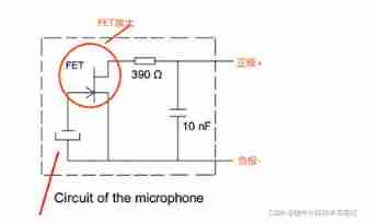
MIC The working current is generally 500uA.
The circuit adopts differential circuit . It has a strong function of restraining interference .
AU_VIN1_N And AU_VIN1_P Access CODEC End .
C201 And C202 Main filtration
C203 It plays the role of filtering differential mode interference in the line .
C204 And C205 It plays the role of filtering common mode interference .
Three kinds of filtering are for MIC Provide a clean power supply .
ACCDET To detect the earphone type . It is connected to CODEC There are two comparators inside . Plug in headphones and three segment headphones , The voltages of the four segment headphones are different .
AU_MICMIAS1 by MIC Provide bias voltage .R204 Is the bias resistance . Mostly 1K. In order to make FET Working at saturation .R203 Yes MIC The sensitivity of plays a certain role . The resistance value should not be too large .R203 Too much leads to MIC Input current is too small . And then affect the dynamic range of the output level . for example , When R203 When the resistance value is too large , The input current is small , The dynamic range of the output level will be smaller as a whole . When there is sound input , Some will be mistakenly given up because of noise or no input , Sensitivity will decrease . When inputting a smaller sound , Will not be available . therefore , When designing hardware , The parameters of this resistor , Consider and choose based on noise and sensitivity .
And then HPH_MIC_N And HPH_MIC_P Get into MIC End .
Suppose the current flowing is I.I=I0+i.I0 It can be understood as DC bias , It is the current under quiet conditions .i It is the current when there is sound input . According to the fluctuation of sound , It is changing . ideally , It is a sinusoidal signal .
Strictly speaking , This circuit is not really differential . Because the common mode voltage of the differential signal is the same , And the above differential connection ,P and N The common mode voltage of is different . Is therefore ,Vbias The fluctuation of will make the common mode voltage change into differential mode voltage , Form noise .
边栏推荐
- Management and use of DokuWiki (supplementary)
- UEFI development learning 4 - getting to know variable services
- Adaptive filter
- How to copy formatted notepad++ text?
- Relationship between line voltage and phase voltage, line current and phase current
- matlab timeserise
- A simple method to prove 1/t Fourier transform
- Altium designer learning (I)
- Measurement fitting based on Halcon learning [III] PM_ measure_ board. Hdev routine
- PMSM dead time compensation
猜你喜欢

Markdown tips
More than 90% of hardware engineers will encounter problems when MOS tubes are burned out!
![[trio basic tutorial 16 from introduction to proficiency] UDP communication test supplement](/img/54/78e4e10724b2762274b06debb10877.jpg)
[trio basic tutorial 16 from introduction to proficiency] UDP communication test supplement
Hardware and software solution of FPGA key chattering elimination
LED display equipment records of the opening ceremony of the Beijing Winter Olympics

研究發現,跨境電商客服系統都有這五點功能!
UEFI development learning 2 - running ovmf in QEMU
How to select conductive slip ring

After installing the new version of keil5 or upgrading the JLINK firmware, you will always be prompted about the firmware update
Ble encryption details
随机推荐
C WinForm [display real-time time in the status bar] - practical exercise 1
Shape template matching based on Halcon learning [v] find_ cocoa_ packages_ max_ deformation. Hdev routine
Class of color image processing based on Halcon learning_ ndim_ norm. hdev
Shell script basic syntax
Hardware 1 -- relationship between gain and magnification
[trio basic from introduction to mastery tutorial 20] trio calculates the arc center and radius through three points of spatial arc
Bootloader implementation of PIC MCU
More than 90% of hardware engineers will encounter problems when MOS tubes are burned out!
Soem EtherCAT source code analysis I (data type definition)
solver. Learning notes of prototxt file parameters
Naming rules for FreeRTOS
Consul安装
Gradle composite construction
如何将EasyCVR平台RTSP接入的设备数据迁移到EasyNVR中?
Soem EtherCAT source code analysis attachment 1 (establishment of communication operation environment)
Baiwen 7-day smart home learning experience of Internet of things
Why is 1900 not a leap year
H264 (I) i/p/b frame gop/idr/ and other parameters
Random function usage notes
研究发现,跨境电商客服系统都有这五点功能!