当前位置:网站首页>External interrupt to realize key experiment
External interrupt to realize key experiment
2022-07-07 08:58:00 【A big cat 1201】
author : A big cat 1201
special column :《STM32 Study 》
Maxim : You just try to , Leave the rest to time !
The external interrupt realizes the key experiment
describe
In the previous article control LED And buzzer button experiment It explains in detail how to pass GPIO Input mode to control LED Status of lights and buzzers . This article is also to realize the function of appeal , But the method is realized by external interrupt , That is to say 4 Each key corresponds to an external interrupt , Control a state in an interrupt program .
Overview of external interrupts
Used by benmew STM32F103ZET6 The chip has 7 Group GPIO, Each group GPIO And then there is 16 individual IO mouth , and STM32 The strength of is , Every one of it IO Both ports support the response of external interrupts , In this way, it has 112 individual IO Port can realize interrupt response , So much IO There are also ways to manage mouth .
- The chip has 19 External interrupt line , Namely :
- Line 0~15: Corresponding to the outside IO The input of the port is interrupted .
- Line 16: Connect to PVD Output .
- Line 17: Connect to RTC Alarm clock event .
- Line 18: Connect to USB Wake Events .
This experiment only uses lines 0 To 15, That is, the interrupt line of external interrupt , other 3 Ben meow will explain in detail when using the broken wire in the root .
You can see , The external interrupt line has 16 root , and IO Oral 112 individual , So there is a mapping relationship between them :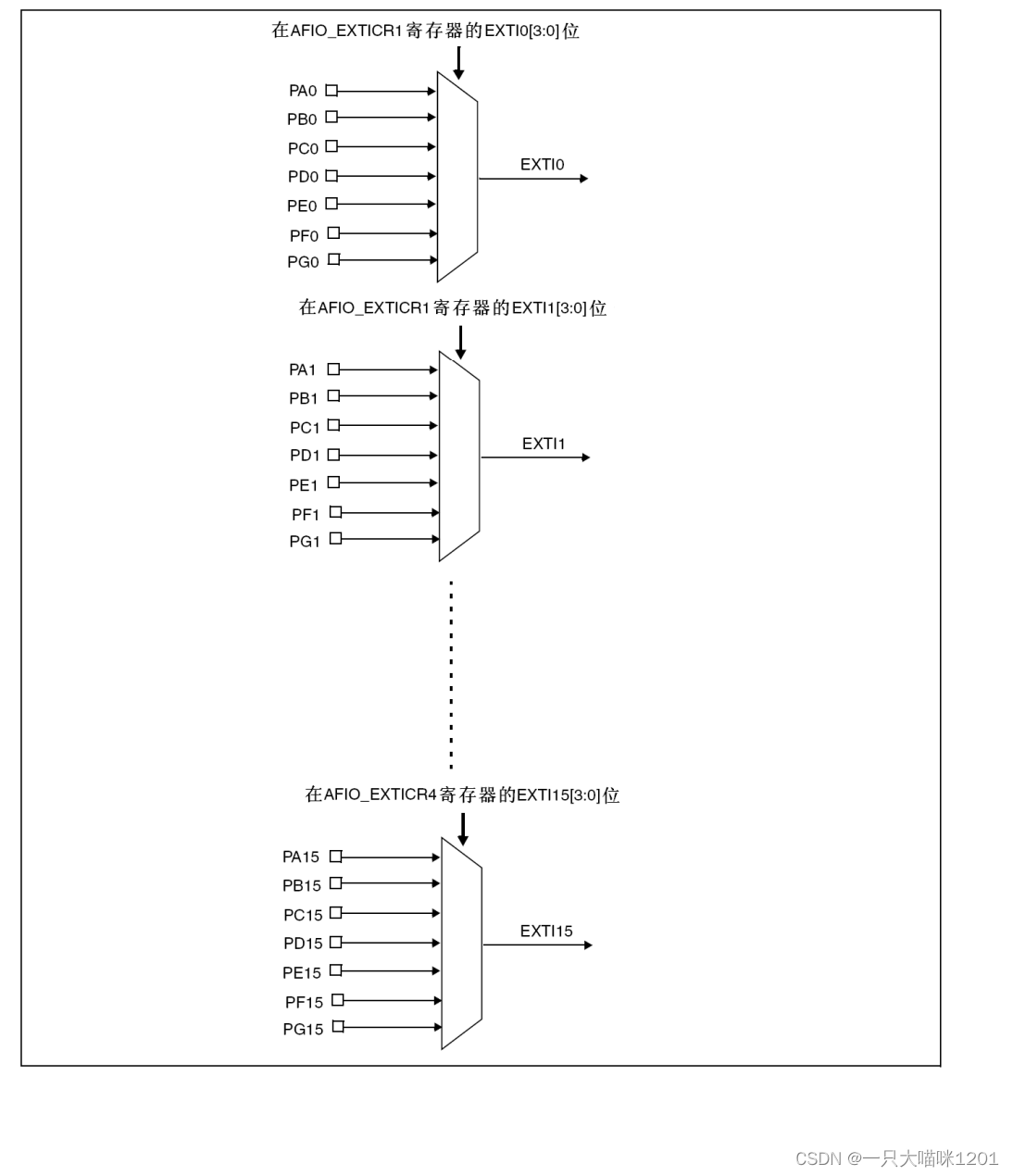
You can see , External interrupt line and GPIO The mapping relationship between is :
- EXIT0 Can be mapped to PA0,PB0,PC0,PD0,PE0,PF0,PG0
- EXIT1 Can be mapped to PA1,PB1,PC1,PD1,PE1,PF1,PG1
- EXIT2 Can be mapped to PA2,PB2,PC2,PD2,PE2,PF2,PG2
- EXIT3 Can be mapped to PA3,PB0,PC3,PD3,PE3,PF3,PG3
…- EXIT14 Can be mapped to PA14,PB14,PC14,PD14,PE14,PF14,PG14
- EXIT15 Can be mapped to PA15,PB15,PC15,PD15,PE15,PF15,PG15
That is to say IO The number of subscript corresponding to the port can be used as the mapping port corresponding to the external interrupt line .
Be careful :
- An external break line can only be mapped to one IO On the mouth , such as EXIT0 Mapped to PA0 On the mouth , here PB0 Can no longer act EXIT0 Mapping port of .
- IO After the port is used as the mapping port , It does not affect reading the IO Port data .
We know , Interrupts have interrupt service functions , Then when the interruption occurs , yes CPU How to execute the corresponding interrupt function ?

The above figure is a table of interrupt vectors , After different external interrupt lines generate interrupt requests and are responded, they will behave like the corresponding interrupt program , The entry of the program is at the corresponding vector address .
- EXIT0 To EXIT4 this 5 Corresponding to external interrupts 5 Two interrupt service functions . After an interrupt occurs and is responded to, it will execute the corresponding interrupt service function .
- EXIT5 To EXIT9 Share an interrupt service function . this 5 After an external interrupt occurs and is responded to, it will enter the same external interrupt service function , So you need to write the judgment code of the response in the function , Determine which interrupt .
- EXIT10 To EXIT15 It also shares an interrupt service function . this 5 After an interrupt occurs and is responded to, it will also enter an interrupt service function .
External interrupt configuration register
External interrupt line and GPIO The mapping relationship of is realized by configuring the external interrupt configuration register , stay AFIO( Auxiliary function register ) The registers in which external interrupts are configured are 3 individual .
- AFIO_EXTICR1
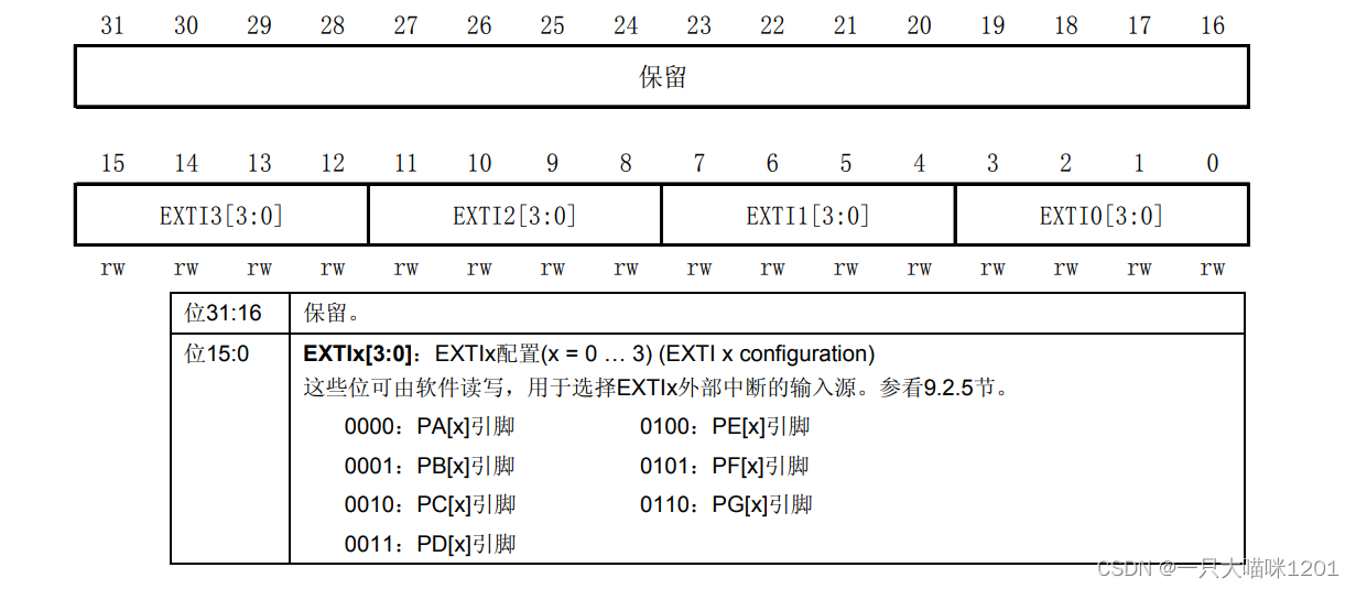
The above figure shows the distribution and specific control of each bit .
- AFIO_EXTICR2
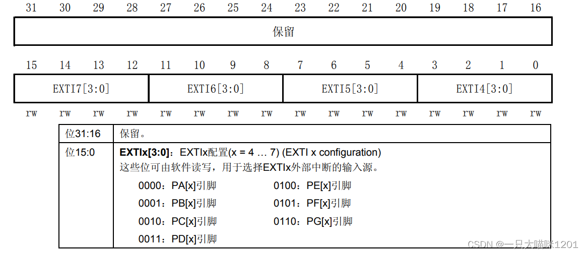
The above figure shows the distribution and specific control of each bit .
- AFIO_EXTICR3
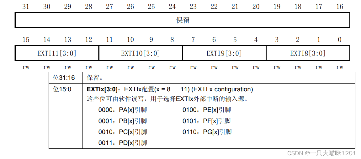
The above figure shows the distribution and specific control of each bit .
ST The official also provides corresponding library functions to configure external interrupt lines and GPIO The mapping relation of
void GPIO_EXTILineConfig(uint8_t GPIO_PortSource, uint8_t GPIO_PinSource);
Using library functions, we don't have to configure each register one by one , The specific use of this function is demonstrated in the code process later in this article .
Experimental code
Since the external interrupt is used to realize the key , Then interrupt service function is essential , And because of the use of LED The lamp , Buzzer , Key , And serial port , Therefore, we also need the initialization functions of these hardware and serial port peripherals .
LED initialization


Through the schematic diagram, we can see LED0 Is with the PB5 Connected ,LED1 Is with the PE5 Connected .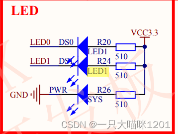
LED0 and LED1 It is the common anode connection method , That is to say PB5 Mouth and PE5 When the port is low LED0 and LED1 bright .
The code is as follows
led.h The code in :
#ifndef __LED_H
#define __LED_H

#include "sys.h"// Bit operation header file reference
#define LED0 PBout(5)
#define LED1 PEout(5)

// For ease of use , Directly use the hardware name to control the state of the lamp

void LED_Init(void);// Function declaration

#endif
led.c The code in :
#include "stm32f10x.h"// Reference top-level header file
#include "led.h"// quote led Initialize header file


void LED_Init()
{

	GPIO_InitTypeDef GPIO_InitStructe;
	RCC_APB2PeriphClockCmd(RCC_APB2Periph_GPIOB|RCC_APB2Periph_GPIOE,ENABLE);// take GPIOB and GPIOE Clock enable

	//PB5 initialization
	GPIO_InitStructe.GPIO_Mode=GPIO_Mode_Out_PP;// Push pull output mode
	GPIO_InitStructe.GPIO_Pin=GPIO_Pin_5;
	GPIO_InitStructe.GPIO_Speed=GPIO_Speed_50MHz;
	GPIO_Init(GPIOB,&GPIO_InitStructe);
	//PE5 initialization
	GPIO_InitStructe.GPIO_Mode=GPIO_Mode_Out_PP;// Push pull output mode
	GPIO_InitStructe.GPIO_Pin=GPIO_Pin_5;
	GPIO_InitStructe.GPIO_Speed=GPIO_Speed_50MHz;
	GPIO_Init(GPIOE,&GPIO_InitStructe);

	// The initial state is that the lights are all off
	LED0=1;
	LED1=1;
}
Buzzer initialization

You can see , The buzzer is connected with PB8 Connected .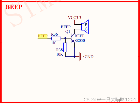
When PB8 When it's high , The buzzer makes a sound .
beep.h The code in :
#ifndef __BEEP_H
#define __BEEP_H

#include "sys.h"
#define beep PBout(8)

void BEEP_Init(void);

#endif
beep.c The code in :
#include "stm32f10x.h"
#include "beep.h"

void BEEP_Init()
{

	GPIO_InitTypeDef GPIO_InitStructe;
	RCC_APB2PeriphClockCmd(RCC_APB2Periph_GPIOB,ENABLE);// take GPIOB and GPIOE Clock enable

	//PB5 initialization
	GPIO_InitStructe.GPIO_Mode=GPIO_Mode_Out_PP;// Push pull output mode
	GPIO_InitStructe.GPIO_Pin=GPIO_Pin_8;
	GPIO_InitStructe.GPIO_Speed=GPIO_Speed_50MHz;
	GPIO_Init(GPIOB,&GPIO_InitStructe);
	// The buzzer is initialized not to sound
	beep=0;
}
Key initialization

You can see ,KEY0 And PE4 Connected to a ,KEY1 And PE3 Connected to a ,KEY2 And PE2 Connected to a .

WK_UP Keys and PA0 Connected to a .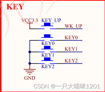
- KEY0 To KEY2 The other end of the is connected to the ground , When the key is pressed, it is low , So this 3 Keys should be set to pull-up input mode .
- WK_UP Connected to high level , When the key is pressed, it is high , So this button should be set to the pull-down input mode .
key.h The code in :
#ifndef __KEY_H

#define __KEY_H
#include "stm32f10x.h"
#define KEY0 GPIO_ReadInputDataBit(GPIOE,GPIO_Pin_4)
#define KEY1 GPIO_ReadInputDataBit(GPIOE,GPIO_Pin_3)
#define KEY2 GPIO_ReadInputDataBit(GPIOE,GPIO_Pin_2)
#define WK_UP GPIO_ReadInputDataBit(GPIOA,GPIO_Pin_0)

#define KEY0_PRES 1
#define KEY1_PRES 2
#define KEY2_PRES 3
#define WK_UP_PRES 4

void KEY_Init(void);


#endif
key.c The code in :
#include "stm32f10x.h"
#include "key.h"
#include "delay.h"


void KEY_Init(void)
{

	GPIO_InitTypeDef GPIO_InitStructe;
	RCC_APB2PeriphClockCmd(RCC_APB2Periph_GPIOA|RCC_APB2Periph_GPIOE,ENABLE);// take GPIOA and GPIOE Clock enable

	//KEY0 To KEY2 Set to pull-up input mode
	GPIO_InitStructe.GPIO_Mode=GPIO_Mode_IPU;
	GPIO_InitStructe.GPIO_Pin=GPIO_Pin_4|GPIO_Pin_3|GPIO_Pin_2;
	GPIO_Init(GPIOE,&GPIO_InitStructe);

	//WK_UP Set it to the pull-down input mode
	GPIO_InitStructe.GPIO_Mode=GPIO_Mode_IPD;
	GPIO_InitStructe.GPIO_Pin=GPIO_Pin_0;
	GPIO_Init(GPIOA,&GPIO_InitStructe);


}
Serial initialization

We can see ,USART1_TX The port multiplexing pin is PA9,USART1_RX The port multiplexing pin is PA10.
as for PB6 and PB7 Is the port remapping pin , Generally, it cannot be used , Interested friends can read this article Port reuse and remapping .
After knowing which pin the serial port is, we need to configure the serial port , Give Way CPU Know that this pin is used as a serial port .
- Pictured above , We use full duplex mode , Need to be aligned PA9 The port is configured as push-pull multiplex output . Yes PA10 Configure as floating or pull-up input .
- Conduct GPIOA and USART1 Clock enable
- Serial port initialization configuration
- Interrupt priority configuration
- Enable receive interrupt
- Open the serial port
After configuring the serial port, you need to write the serial port interrupt service function .
See benmew's article for the agreement of serial communication Serial port experiment —— Simple data sending and receiving .
Ben meow won't explain how to write in detail here , Go straight to the code :
usart.h The code in :
#include "sys.h"
#include "usart.h"
#if SYSTEM_SUPPORT_OS
#include "includes.h" //ucos  Use
#endif
#ifndef __USART_H
#define __USART_H

#include "stdio.h"
#include "sys.h"

#define USART_REC_LEN 200 // Define the maximum number of bytes received  200
#define EN_USART1_RX 1 // Can make (1)/ prohibit (0) A serial port 1 receive
extern u8  USART_RX_BUF[USART_REC_LEN]; // Receive buffer , Maximum USART_REC_LEN Bytes . The last byte is a newline character
extern u16 USART_RX_STA;         		// Receive status flag
void uart_init(u32 bound);


#endif
usart.c The code in :
#if 1
#pragma import(__use_no_semihosting)
// Support functions required by the standard library
struct __FILE
{

	int handle;

};

FILE __stdout;
// Definition _sys_exit() To avoid using semi host mode
void _sys_exit(int x)
{

	x = x;
}
// redefinition fputc function
int fputc(int ch, FILE *f)
{

	while((USART1->SR&0X40)==0);// Cycle to send , Until it's sent
    USART1->DR = (u8) ch;
	return ch;
}
#endif

/* Use microLib Methods */
 /* int fputc(int ch, FILE *f) { USART_SendData(USART1, (uint8_t) ch); while (USART_GetFlagStatus(USART1, USART_FLAG_TC) == RESET) {} return ch; } int GetKey (void) { while (!(USART1->SR & USART_FLAG_RXNE)); return ((int)(USART1->DR & 0x1FF)); } */

#if EN_USART1_RX // If enabled, receive
// A serial port 1 Interrupt service routine
// Be careful , Read USARTx->SR Can avoid inexplicable mistakes
u8 USART_RX_BUF[USART_REC_LEN];     // Receive buffer , Maximum USART_REC_LEN Bytes .
// Reception status
//bit15,  Receive completion flag
//bit14,  Received 0x0d
//bit13~0,  Number of valid bytes received
u16 USART_RX_STA=0;       // Receive status flag

void uart_init(u32 bound)
{

	GPIO_InitTypeDef GPIO_InitStructe;
	USART_InitTypeDef USART_InitStructe;
	NVIC_InitTypeDef NVIC_InitStructe;
	RCC_APB2PeriphClockCmd(RCC_APB2Periph_GPIOA|RCC_APB2Periph_USART1,ENABLE);

	//PA9 Initialize to multiplex push-pull output , Reuse as USART1_TX
	GPIO_InitStructe.GPIO_Pin=GPIO_Pin_9;
	GPIO_InitStructe.GPIO_Speed=GPIO_Speed_50MHz;
	GPIO_InitStructe.GPIO_Mode=GPIO_Mode_AF_PP;
	GPIO_Init(GPIOA,&GPIO_InitStructe);

	//PA10 Initialize as floating input , Reuse as USART1_RX
	GPIO_InitStructe.GPIO_Pin=GPIO_Pin_10;
	GPIO_InitStructe.GPIO_Mode=GPIO_Mode_IN_FLOATING;
	GPIO_Init(GPIOA,&GPIO_InitStructe);

	//USART1 initialization
	USART_InitStructe.USART_BaudRate=bound;// Baud rate
	USART_InitStructe.USART_WordLength=USART_WordLength_8b;// The word is 8 Bytes
	USART_InitStructe.USART_StopBits=USART_StopBits_1;// Stop bit 1 position
	USART_InitStructe.USART_Parity=USART_Parity_No;// No parity bit
	USART_InitStructe.USART_Mode=USART_Mode_Rx|USART_Mode_Tx;// Receive and send
	USART_InitStructe.USART_HardwareFlowControl=USART_HardwareFlowControl_None;// V. hardware flow control
	USART_Init(USART1,&USART_InitStructe);

	// Interrupt priority initialization
	NVIC_InitStructe.NVIC_IRQChannel=USART1_IRQn;//USART1 Channel interrupt
	NVIC_InitStructe.NVIC_IRQChannelPreemptionPriority=3;// Preemption priority is 3
	NVIC_InitStructe.NVIC_IRQChannelSubPriority=3;// The response priority is 3
	NVIC_InitStructe.NVIC_IRQChannelCmd=ENABLE;// Channel enable
	NVIC_Init(&NVIC_InitStructe);

	// Receive interrupt enable
	USART_ITConfig(USART1,USART_IT_RXNE,ENABLE);

	// Can make USART1
	USART_Cmd(USART1,ENABLE);
}

void USART1_IRQHandler(void)
{

	u8 res=0;
#if SYSTEM_SUPPORT_OS // If SYSTEM_SUPPORT_OS It's true , Support is needed OS.
	OSIntEnter();
#endif
	// Judge whether the reception interrupt occurs
	if(USART_GetITStatus(USART1,USART_IT_RXNE)!=RESET)
	{

		res=USART_ReceiveData(USART1);// Receive the read data
		if((USART_RX_STA&0x8000)==0)// Whether the reception is incomplete
		{

			if(USART_RX_STA&0x4000)// Did you receive it 0x0d
			{

				// If you receive 0x0a
				if(res!=0x0a)
					USART_RX_STA=0;// If not , Description receive error , The whole sign is clear 0
				else
					USART_RX_STA|=0x8000;// The reception is complete
			}
			else// I haven't received 0x0d
			{

				// If you receive 0x0d
				if(res==0x0d)
					USART_RX_STA|=0x0400;// receive 0x0d Logo location 1
				else// Received is not 0x0d
				{

					// Store the received data in the array
					USART_RX_BUF[USART_RX_STA&0x3FFF]=res;
					USART_RX_STA++;
					// If the number of data is greater than the maximum receiving length
					if(USART_RX_STA>(USART_REC_LEN-1))
						USART_RX_STA=0;// Receive error , The flag is clear 0
				}
			}
		}
	}
#if SYSTEM_SUPPORT_OS // If SYSTEM_SUPPORT_OS It's true , Support is needed OS.
	OSIntExit();
#endif
}
#endif
External interrupt initialization
Next is the most important step , Initialization of external interrupt
- Make it usable GPIO mouth
Here we use the PE4,PE3,PE2,PA0 four GPIO mouth
What will be used GPIO Set to input mode
Can make AFIO Register clock
This register controls the mapping of interrupt lines , So it must be enabled
- Set the mapping relationship of the external break line
- EXIT4 Mapping to PE4
- EXIT3 Mapping to PE3
- EXIT2 Mapping to PE2
- EXIT0 Mapping to PA0
- External interrupt initialization
- PE4,PE3,PE2 this 3 individual IO The port adopts the pull-up input mode , When a key is pressed , The IO The port is low
- therefore 3 individual IO The port should be set as the falling edge to trigger the interrupt .
- PA0 It adopts the pull-down input mode , When a key is pressed , The IO The port is high
- therefore PA0 To set the rising edge to trigger interrupt .
- Interrupt priority initialization
- The interrupt channel is EXIT0,EXIT4,EXIT3,EXIT2, altogether 4 Channels
- The preemption priority is set to 2
- The response priority is set to 2
- Enable interrupt channel
- Write interrupt service function
- External interrupt line 0 The corresponding is WK_UP Key interrupt , When the key is pressed, the state of the buzzer reverses .
- External interrupt line 4 The corresponding is KEY0 Key interrupt , When the last two keys are pressed LED The state of is reversed at the same time .
- External interrupt line 3 The corresponding is KEY1 Key interrupt , When the key is pressed LED0 The state of is reversed .
- External interrupt line 2 The corresponding is KEY2 Key interrupt , When the key is pressed LED1 The state of is reversed .
- Clears the interrupt flag bit
The interrupt flag bit of the external interrupt will be set by the hardware after the interrupt occurs 1, However, the hardware will not be reset automatically after the interrupt service function is executed , So we need to manually clear the flag at the end of the interrupt service function 0.
exit.h The code in :
#ifndef __EXIT_H
#define __EXIT_H

void EXIT_Init(void);

#endif
exit.c The code in :
#include "exit.h"
#include "stm32f10x.h"
#include "led.h"
#include "beep.h"
#include "delay.h"
#include "key.h"

void EXIT_Init(void)
{

	EXTI_InitTypeDef EXTI_InitStructe;
	NVIC_InitTypeDef NVIC_InitStructe;
	RCC_APB2PeriphClockCmd(RCC_APB2Periph_GPIOE|RCC_APB2Periph_GPIOA,ENABLE);// Can make GPIOA and GPIOE Group clock
	RCC_APB2PeriphClockCmd(RCC_APB2Periph_AFIO,ENABLE);// Can make AFIO The clock

	KEY_Init();

	// External interrupt line 4 initialization
	GPIO_EXTILineConfig(GPIO_PortSourceGPIOE,GPIO_PinSource4);//exit4
	EXTI_InitStructe.EXTI_Line=EXTI_Line4;// trunk 4
	EXTI_InitStructe.EXTI_LineCmd=ENABLE;
	EXTI_InitStructe.EXTI_Mode=EXTI_Mode_Interrupt;// The mode is interrupt
	EXTI_InitStructe.EXTI_Trigger=EXTI_Trigger_Falling;// Falling edge trigger mode
	EXTI_Init(&EXTI_InitStructe);

	// External interrupt line 3 initialization
	GPIO_EXTILineConfig(GPIO_PortSourceGPIOE,GPIO_PinSource3);//exit3
	EXTI_InitStructe.EXTI_Line=EXTI_Line3;// trunk 3
	EXTI_Init(&EXTI_InitStructe);

	// External interrupt line 2 initialization
	GPIO_EXTILineConfig(GPIO_PortSourceGPIOE,GPIO_PinSource2);//exit2
	EXTI_InitStructe.EXTI_Line=EXTI_Line2;// trunk 2
	EXTI_Init(&EXTI_InitStructe);

	// External interrupt line 0 initialization
	GPIO_EXTILineConfig(GPIO_PortSourceGPIOA,GPIO_PinSource0);//exit0
	EXTI_InitStructe.EXTI_Line=EXTI_Line0;// trunk 0
	EXTI_InitStructe.EXTI_Trigger=EXTI_Trigger_Rising;// Rising edge trigger mode
	EXTI_Init(&EXTI_InitStructe);

	// Interrupt initialization
	NVIC_InitStructe.NVIC_IRQChannel=EXTI0_IRQn;// Channel external channel 0
	NVIC_InitStructe.NVIC_IRQChannelCmd=ENABLE;
	NVIC_InitStructe.NVIC_IRQChannelPreemptionPriority=0x02;// The preemption priority is set to 2
	NVIC_InitStructe.NVIC_IRQChannelSubPriority=0x00;// The response priority is set to 2

	NVIC_Init(&NVIC_InitStructe);
	NVIC_InitStructe.NVIC_IRQChannel=EXTI4_IRQn;// Channel external channel 4
	NVIC_InitStructe.NVIC_IRQChannelCmd=ENABLE;
	NVIC_InitStructe.NVIC_IRQChannelPreemptionPriority=0x02;// The preemption priority is set to 2
	NVIC_InitStructe.NVIC_IRQChannelSubPriority=0x01;// The response priority is set to 2
	NVIC_Init(&NVIC_InitStructe);
	NVIC_InitStructe.NVIC_IRQChannel=EXTI3_IRQn;// Channel external channel 3
	NVIC_InitStructe.NVIC_IRQChannelCmd=ENABLE;
	NVIC_InitStructe.NVIC_IRQChannelPreemptionPriority=0x02;// The preemption priority is set to 2
	NVIC_InitStructe.NVIC_IRQChannelSubPriority=0x02;// The response priority is set to 2
	NVIC_Init(&NVIC_InitStructe);
	NVIC_InitStructe.NVIC_IRQChannel=EXTI2_IRQn;// Channel external channel 2
	NVIC_InitStructe.NVIC_IRQChannelCmd=ENABLE;
	NVIC_InitStructe.NVIC_IRQChannelPreemptionPriority=0x02;// The preemption priority is set to 2
	NVIC_InitStructe.NVIC_IRQChannelSubPriority=0x03;// The response priority is set to 2
	NVIC_Init(&NVIC_InitStructe);
}

void EXTI0_IRQHandler(void)
{

	delay_ms(10);// Delay chattering
	// Determine if it is WK_UP Key pressed
	if(WK_UP==1)
	{

		beep=!beep;// The buzzer state is reversed
	}
	EXTI_ClearITPendingBit(EXTI_Line0);
}

void EXTI4_IRQHandler(void)
{

	delay_ms(10);// Delay chattering
	// Determine if it is KEY0 Key pressed
	if(KEY0==0)
	{

		LED0=!LED0;
		LED1=!LED1;// Two LED The light state is reversed at the same time
	}
	EXTI_ClearITPendingBit(EXTI_Line4);
}

void EXTI3_IRQHandler(void)
{

	delay_ms(10);// Delay chattering
	// Determine if it is KEY1 Key pressed
	if(KEY1==0)
	{

		LED0=!LED0;//LED0 The state is reversed
	}
	EXTI_ClearITPendingBit(EXTI_Line3);
}

void EXTI2_IRQHandler(void)
{

	delay_ms(10);// Delay chattering
	// Determine if it is KEY2 Key pressed
	if(KEY2==0)
	{

		LED1=!LED1;//LED1 The state is reversed
	}
	EXTI_ClearITPendingBit(EXTI_Line2);
}
Effect display
It takes a long time to upload videos , The effect of this experiment is similar to control LED Lamp and buzzer experiment The effect is the same , The serial port part of the experiment has the same effect as Serial port experiment —— Simple data sending and receiving The effect is the same .
If you want to see the experimental results, you can move to the two articles mentioned above .
边栏推荐
- Screen automatically generates database documents
- Why choose cloud native database
- Simple use of Xray
- 测试人一定要会的技能:selenium的三种等待方式解读,清晰明了
- 最长上升子序列模型 AcWing 1017. 怪盗基德的滑翔翼
- Calf problem
- Vagrant failed to mount directory mount: unknown filesystem type 'vboxsf'
- Opencv converts 16 bit image data to 8 bits and 8 to 16
- 数字三角形模型 AcWing 1027. 方格取数
- Mountaineering team (DFS)
猜你喜欢

On December 8th, 2020, the memory of marketing MRC application suddenly increased, resulting in system oom
LeetCode 715. Range 模块

Esp32-ulp coprocessor low power mode RTC GPIO interrupt wake up

外部中断实现按键实验

最长上升子序列模型 AcWing 1017. 怪盗基德的滑翔翼
![[Nanjing University] - [software analysis] course learning notes (I) -introduction](/img/57/bf652b36389d2bf95388d2eb4772a1.png)
[Nanjing University] - [software analysis] course learning notes (I) -introduction
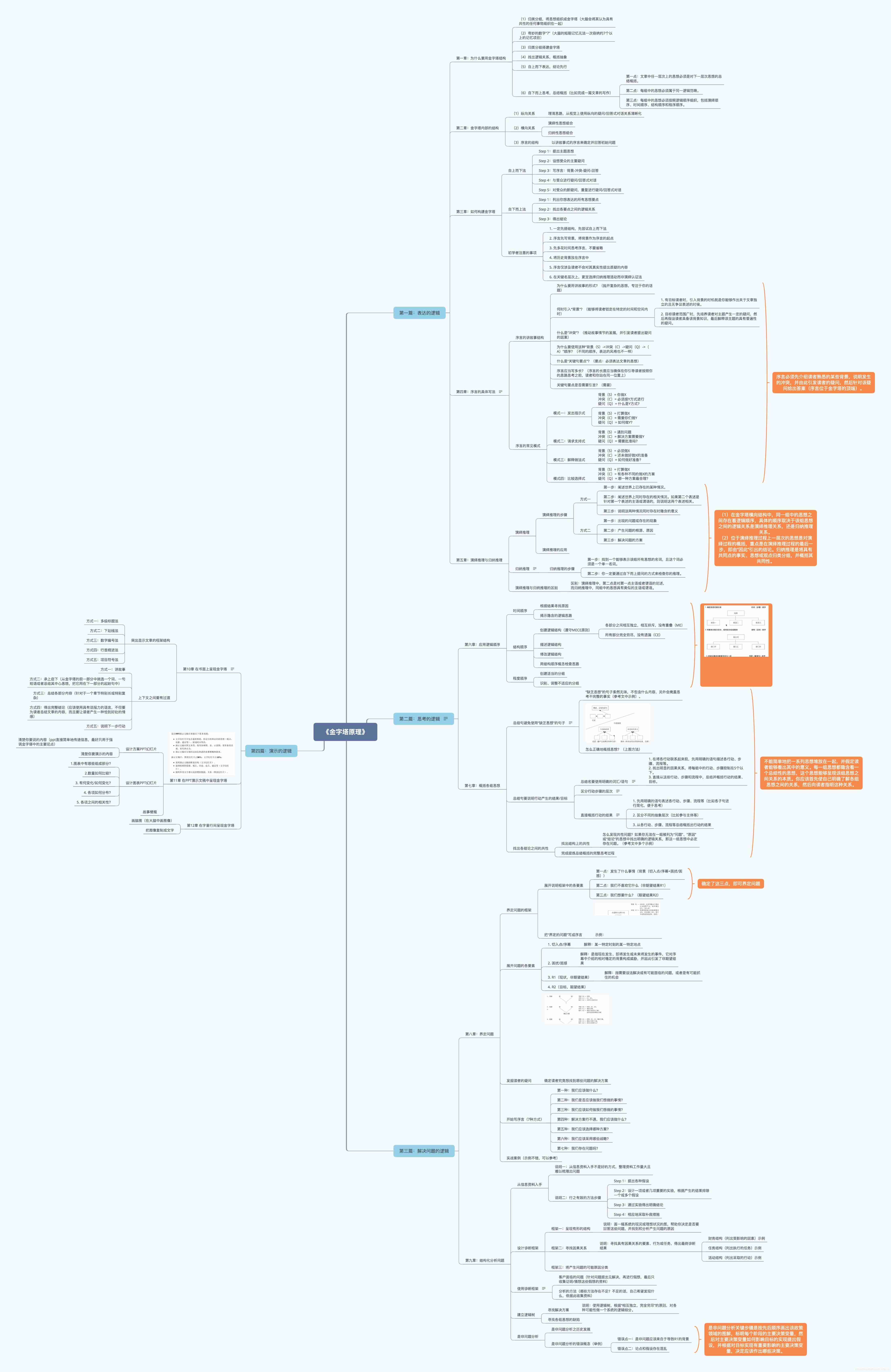
Reading notes of pyramid principle
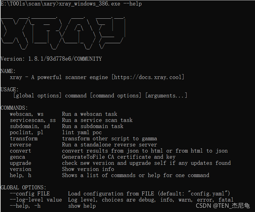
Simple use of Xray
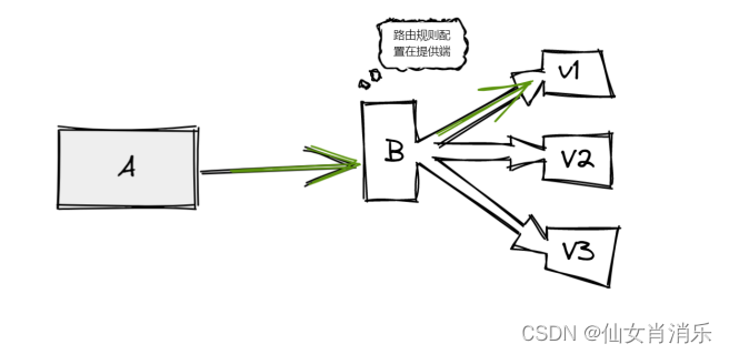
【Istio Network CRD VirtualService、Envoyfilter】

数字三角形模型 AcWing 1027. 方格取数
随机推荐
Mountaineering team (DFS)
Simulation volume leetcode [general] 1705 The maximum number of apples to eat
Shell script for changing the current folder and the file date under the folder
Sign and authenticate API interface or H5 interface
Three updates to build applications for different types of devices | 2022 i/o key review
With an annual salary of 50W, Alibaba P8 will come out in person to teach you how to advance from testing
Several common database connection methods
How to add a mask of a target in a picture
NVIC中断优先级管理
【ChaosBlade:根据标签删除POD、Pod 域名访问异常场景、Pod 文件系统 I/O 故障场景】
Digital triangle model acwing 1027 Grid access
Enterprise manager cannot connect to the database instance
Greenplum 6.x common statements
模拟卷Leetcode【普通】1706. 球会落何处
Reflections on the way of enterprise IT architecture transformation (Alibaba's China Taiwan strategic thought and architecture practice)
Alibaba P8 teaches you how to realize multithreading in automated testing? Hurry up and stop
GoLand set goproxy
年薪50w阿裏P8親自下場,教你如何從測試進階
Find the original code, inverse code and complement of signed numbers [C language]
Routing information protocol rip
