当前位置:网站首页>Verilog timing control
Verilog timing control
2022-07-02 03:08:00 【Da Xi】
Verilog Timing control
key word : Time delay control , Events trigger , edge-triggered , Level trigger
Verilog Provides 2 A large class of timing control methods : Time delay control and event control . Event control is mainly divided into edge triggered event control and level sensitive event control .
Time delay control
Time delay based timing control appears in the expression , It specifies the time interval between the beginning of execution and the end of execution of the statement .
The delay can be digital 、 Identifier or expression .
According to the position difference in the expression , Time delay control can be divided into conventional time delay and embedded time delay .
Conventional delay
In case of conventional delay , This statement needs to wait for a certain time , Then assign the calculation result to the target signal .
The format is :#delay procedural_statement, for example :
reg  value_test ;
reg  value_general ;
#10  value_general    = value_test ;
Another way to write this time delay method is to directly put the well number # Separate into a delay execution statement , for example :
#10 ;
value_ single         = value_test ;
Embedded delay
In case of embedded delay , This statement first saves the calculation results , Then wait for a certain time and assign a value to the target signal .
Embedded time delay control is added after the assignment number . for example :
reg  value_test ;
reg  value_embed ;
value_embed        = #10 value_test ;
It should be noted that , this 2 The effect of two time-delay control methods is different .
When the right end of the assignment symbol of the delay statement is a constant ,2 All kinds of delay control can achieve the same delay assignment effect .
When the right end of the assignment symbol of the delay statement is a variable ,2 This kind of delay control may produce different delay assignment effects .
For example, the following simulation code :
example
`timescale 1ns/1ns
module test ;
reg value_test ;
reg value_general, value_embed, value_single ;
//signal source
initial begin
value_test = 0 ;
#25 ; value_test = 1 ;
#35 ; value_test = 0 ; //absolute 60ns
#40 ; value_test = 1 ; //absolute 100ns
#10 ; value_test = 0 ; //absolute 110ns
end
//(1)general delay control
initial begin
value_general = 1;
#10 value_general = value_test ; //10ns, value_test=0
#45 value_general = value_test ; //55ns, value_test=1
#30 value_general = value_test ; //85ns, value_test=0
#20 value_general = value_test ; //105ns, value_test=1
end
//(2)embedded delay control
initial begin
value_embed = 1;
value_embed = #10 value_test ; //0ns, value_test=0
value_embed = #45 value_test ; //10ns, value_test=0
value_embed = #30 value_test ; //55ns, value_test=1
value_embed = #20 value_test ; //85ns, value_test=0
end
//(3)single delay control
initial begin
value_single = 1;
#10 ;
value_single = value_test ; //10ns, value_test=0
#45 ;
value_single = value_test ; //55ns, value_test=1
#30 ;
value_single = value_test ; //85ns, value_test=0
#20 ;
value_single = value_test ; //105ns, value_test=1
end
always begin
#10;
if ($time >= 150) begin
$finish ;
end
end
endmodule
The simulation results are as follows , It can be seen from the picture that :
- (1) Generally, the results of the two expressions of delay are consistent .
- (2) General time delay assignment : Delay for a certain time after encountering a delayed statement , Then assign the current operand to the target signal , did not " Inertia delay " Characteristics , Relatively narrow pulses will not be missed .
- (3) Embedded delay assignment : After encountering deferred statements , First calculate the result at the right end of the expression , Then delay for a certain time , Assign a value to the target signal .

Next, the assignment process of embedded delay is analyzed :
value_embed = #10 value_test ; //0ns, value_test=0
0ns when , Execute this delay statement .
First the 0 Assign to signal value_embed, Delay 10ns Output is 0;
value_embed = #45 value_test ; //10ns, value_test=0
10ns when , Execute this delay statement .
Because of this time value_test Still for 0, therefore value_embed The value remains the same .
That is to 55ns when ,value_embed The value remains 0.
value_embed = #30 value_test ; //55ns, value_test=1
Empathy ,55ns when ,value_test The value is 1, Assign it to value_embed And delay 30ns Output .
therefore 85ns when ,value_embed Output is 1.
value_embed = #20 value_test ; //85ns, value_test=0
Empathy ,105ns when ,value_embed Output is 0.
Edge trigger event control
stay Verilog in , An event is an event reg or wire The value of type variable has changed .
The timing control based on event triggering is mainly divided into the following types .
General event control
Symbols for event control @ Express .
The condition for statement execution is that the value of the signal changes specifically .
keyword posedge It refers to the edge forward jump of the signal ,negedge It refers to the negative edge jump of the signal , When the jump direction is not specified , be 2 Edge changes in both cases trigger related events . for example :
example
// The signal clk As long as it changes , Is executed q<=d, On both sides D Trigger model
always @(clk) q <= d ;
// On the signal clk Rising edge moment , perform q<=d, Positive edge D Trigger model
always @(posedge clk) q <= d ;
// On the signal clk Falling edge moment , perform q<=d, Negative edge D Trigger model
always @(negedge clk) q <= d ;
// Calculate immediately d Value , And in clk The rising edge time is assigned to q, This style of writing is not recommended
q = @(posedge clk) d ;
Named event control
Users can declare event( event ) Variable of type , And trigger the variable to identify whether the event occurs . Name events with keywords event To declare , Trigger signal is used -> Express . for example :
example
event start_receiving ;
always @( posedge clk_samp) begin
-> start_receiving ; // The rising edge of the sampling clock is used as the time trigger time
end
always @(start_receiving) begin
data_buf = {data_if[0], data_if[1]} ; // Trigger time , Integration of multidimensional data
end
Sensitive list
When a change in any one of multiple signals or events can trigger the execution of a statement ,Verilog Use in " or " Expression to describe this situation , With keywords or Connect multiple events or signals . The list of these events or signals is called " Sensitive list ". Of course ,or You can also use commas , Instead of . for example :
example
// With low effective reset end D Trigger model
always @(posedge clk or negedge rstn) begin
//always @(posedge clk , negedge rstn) begin
// You can also use commas to display multiple event triggers
if(! rstn)begin
q <= 1'b ;
end
else begin
q <= d ;
end
end
When there are many input variables in combinatorial logic , Then writing sensitive lists can be cumbersome . here , A more concise way of writing is @* or @(*), Indicates that it is sensitive to changes in all input variables in the statement block . for example :
example
always @(*) begin
//always @(a, b, c, d, e, f, g, h, i, j, k, l, m) begin
// The two expressions are equivalent
assign s = a? b+c : d ? e+f : g ? h+i : j ? k+l : m ;
end
Level sensitive event control
The event control discussed above all needs to wait for the change of signal value or the triggering of events , Use @+ Sensitive list The way to express .
Verilog It also supports the use of level as a sensitive signal to control timing , That is, the execution of the following statement needs to wait for a condition to be true .Verilog Use keywords in wait To represent this level sensitivity . for example :
example
initial begin
wait (start_enable) ; // wait for start The signal
forever begin
//start After the signal is enabled , stay clk_samp Rising edge , Integrating data
@(posedge clk_samp) ;
data_buf = {data_if[0], data_if[1]} ;
end
end
边栏推荐
- [road of system analyst] collection of wrong topics in enterprise informatization chapter
- 2022-2028 global nano abrasive industry research and trend analysis report
- After marriage
- 2022-2028 global human internal visualization system industry research and trend analysis report
- ORA-01547、ORA-01194、ORA-01110
- West digital decided to raise the price of flash memory products immediately after the factory was polluted by materials
- Unit · elementary C # learning notes
- Baohong industry | 6 financial management models at different stages of life
- Baohong industry | four basic knowledge necessary for personal finance
- Mathematical calculation in real mode addressing
猜你喜欢

2022-2028 global military computer industry research and trend analysis report
![[staff] the direction of the symbol stem and the connecting line (the symbol stem faces | the symbol stem below the third line faces upward | the symbol stem above the third line faces downward | the](/img/fe/d97b25f702bbc05f941d08147259e0.jpg)
[staff] the direction of the symbol stem and the connecting line (the symbol stem faces | the symbol stem below the third line faces upward | the symbol stem above the third line faces downward | the
Formatting logic of SAP ui5 currency amount display

Après le mariage
el-table的render-header用法
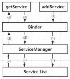
Systemserver service and servicemanager service analysis
![寻找重复数[抽象二分/快慢指针/二进制枚举]](/img/9b/3c001c3b86ca3f8622daa7f7687cdb.png)
寻找重复数[抽象二分/快慢指针/二进制枚举]
After marriage
![[road of system analyst] collection of wrong topics in enterprise informatization chapter](/img/c4/0bb4823ca85c440b4e0587a91b2585.jpg)
[road of system analyst] collection of wrong topics in enterprise informatization chapter
2022-2028 global encryption software industry research and trend analysis report
随机推荐
2022 hoisting machinery command examination paper and summary of hoisting machinery command examination
Redis cluster
PMP personal sprint preparation experience
ZABBIX API creates hosts in batches according to the host information in Excel files
West digital decided to raise the price of flash memory products immediately after the factory was polluted by materials
Calculation of page table size of level 2, level 3 and level 4 in protection mode (4k=4*2^10)
A list of job levels and salaries in common Internet companies. Those who have conditions must enter big factories. The salary is really high
使用 useDeferredValue 进行异步渲染
C shallow copy and deep copy
寻找重复数[抽象二分/快慢指针/二进制枚举]
MongoDB非關系型數據庫
[road of system analyst] collection of wrong topics in enterprise informatization chapter
2022-2028 global nano abrasive industry research and trend analysis report
[staff] pitch representation (bass clef | C1 36 note pitch representation | C2 48 note pitch representation | C3 60 note pitch representation)
流线线使用阻塞还是非阻塞
高并发场景下缓存处理方案
【JVM】创建对象的流程详解
Pychart creates new projects & loads faster & fonts larger & changes appearance
How does proxy IP participate in the direct battle between web crawlers and anti crawlers
3124. Word list