当前位置:网站首页>20 kinds of hardware engineers must be aware of basic components | the latest update to 8.13
20 kinds of hardware engineers must be aware of basic components | the latest update to 8.13
2022-07-04 10:56:00 【Eric%258436】
** If there is a mistake , Thank you for correcting **
If there is a mistake , Thank you for correcting , Please send a private message to the blogger , There is a red envelope for hard work , Worship “ one-word teacher ”.
Please find the paragraphs you need according to the table of contents
The knowledge in this chapter is part of the basic course of hardware engineer Basic components
First of all, we need to know why we should learn hardware ?
The answer is, of course, for the romance of iron man ! Which engineer doesn't like sexy armor ?
The learning order is : resistance 、 capacitance 、 inductance ( transformer )、 insurance 、 diode ( Rectifier bridge )、 triode 、 Connector 、 Buzzer 、IGBT、 Power converter 、 Crystal oscillator 、 Relay 、 Optocoupler 、 Buffer 、 trigger 、 Counter 、 Isolation amplifier 、 Operational release 、 Voltage reference source 、555 Timer .
From basic to advanced , Layers of depth . Kung Fu is out of the question , There are many deficiencies in this chapter , The explanation is not deep enough , Welcome to the comment area or private letter to discuss .
Click to open it , Sorting is not easy to , White whoring is not very good . Ask for a little praise !!!
resistance
Classification of resistance
Common are : Chip resistance ( Most commonly used )、 Varistor 、 Power resistance
Besides , And carbon film resistors , Metal film resistance , Cylindrical patch resistor , Resistance bar , Photosensitive resistor , Cement resistance , Wound ceramic resistor
What is resistance :. The obstruction of conductors to the passage of current . The resistance of a conductor varies with its length 、 Section size 、 Temperature and conductor composition change . The unit is Ohm .( Volt ampere characteristics ) Resistance is a description of the conductive characteristics of a conductor !( Usually speaking, it refers to resistor )
Volt ampere characteristics : Volt ampere characteristic curve , The ordinate represents the current , The abscissa represents the voltage , Drawn with this I-U The image is called the volt ampere characteristic curve of the conductor , It is often used to study the change law of conductor resistance
linear R=U/I
Nonlinear resistance : Such as varistor , Thermistor
Basic parameters of resistance :resistance ,
Rated power (P=I^2*R In general use 1/4w and 1/8w Of , Indicates a current withstand capability ),
Permissible error
Common expressions of resistance are : Color ring resistance identification method ( Color code method ) And direct method
Common resistance measurement methods are : Universal meter and digital bridge
The representation of resistance in schematic diagram :
PCB Schematic representation :
R1 Varistor ,R3 Ordinary resistance ,R4 Sliding resistance
The function of resistance :
partial pressure
Current limiting
Thermometry
Anti surgeHow to choose resistance :
1. function ;
2. main parameter ( resistance , power , precision );
3. voltage
Varistor
Varistor is an element with transient voltage suppression function , It can be used to replace the transient suppression diode 、 Combination of Zener diode and capacitor . Varistors can be used for IC And circuits of other equipment , Prevent electrostatic discharge 、 Surge and other transient currents ( Such as lightning ) And cause damage to them . When in use, it is only necessary to connect the varistor in parallel with the protected IC Or equipment circuit , When the voltage is momentarily higher than a - Numerical time , The resistance of varistor drops rapidly , Turn on a large current , To protect IC Or electrical equipment ; When the voltage is lower than the working voltage of the varistor , The resistance value of varistor is very high , Almost open , Therefore, it will not affect the normal operation of devices or electrical equipment .
principle : Varistors are widely used in household appliances and other electronic products , Overvoltage protection 、 lightning protection 、 Suppress surge current 、 Absorb spikes 、 Limiting 、 High voltage arc extinguishing 、 Denoising 、 Protect semiconductor components and other functions .
Circuit connection diagram for circuit surge and transient protection with pressure-sensitive voltage device . For the application of varistor connection , It can be roughly divided into four types :The first type is the connection between power lines or between power lines and the earth . As a varistor , The most representative application occasion is to protect electronic products when the power line and long-distance transmission signal line encounter lightning strike and there are surge pulses in the conductor . Generally, the varistor connected between lines can be effective for the induction pulse between lines , And the varistor connected between the line and the ground is effective for the induction pulse between the transmission line and the earth . If we further combine the two forms of line to line connection and line to ground connection , It can better absorb surge pulses .
The second type is the connection in the load . It is mainly used for sudden opening and closing of pantograph under inductive load | Start the induction pulse to absorb , To prevent components from being damaged .- In general , As long as it is connected in parallel to the inductive load , But according to the type of current and the size of energy , You can consider working with R - C The series absorption circuit is used .
The third type is the connection between contacts . This connection is mainly to prevent the contact of the inductive charge switch from being burnt out by the arc ,- Generally, connect the varistor in parallel with the contact .
The fourth type is mainly used for the protective connection of semiconductor devices . This connection mode is mainly used for SCR 、 High power triode and other semiconductor devices , Generally, it is connected in parallel with protective devices , To limit the voltage lower than the withstand voltage level of the protected device , This pair of semiconductor devices is - An effective protection .
Thermocouple
working principle : If two homogeneous conductors with different components form a circuit , The direct temperature measuring end is called the measuring end , The terminal is called the reference terminal , When there is a temperature difference at both ends , Current will be generated in the circuit , Then there will be Seebeck Thermal potential , The Seebeck effect . The magnitude of thermoelectric potential is only related to the material of thermocouple conductor and the temperature difference at both ends , Length with thermocouple conductor 、 Diameter independent .
characteristic : Simple construction 、 Applicable to a wide range of temperatures 、 Easy to use 、 Withstand heat 、 Strong mechanical impact ability and fast response , Commonly used in high temperature areas 、 Harsh environment such as large vibration and impact and suitable for temperature measurement of micro structures ; But its signal output sensitivity is relatively low , Vulnerable to environmental interference signals and preamplifier temperature drift , Therefore, it is not suitable for measuring small temperature changes .
Thermistor
Thermistor , Including positive temperature coefficient (PTC) And negative temperature coefficient (NTC) Thermistor . The main features of thermistors are :① High sensitivity , Its resistance temperature coefficient is larger than that of metal 10~ 100 More than times ;② Wide operating temperature range , Normal temperature devices are suitable for -55C~ 315C, High temperature devices are suitable for temperatures higher than 315C ( At present, the maximum can reach 2000C) Low temperature devices are suitable for -273C~55C; ③ Small volume , Be able to measure gaps that cannot be measured by other thermometers 、 The temperature of blood vessels in cavities and organisms ;④ Easy to use , The resistance value can be in 0.1~ 100k Any choice between ;⑤ Easy to process into complex shapes , Can mass produce ;⑥ Good stability 、 Strong overload capacity .
Because semiconductor thermistor has unique performance , Therefore, in application, it can not only be used as a measuring element ( Like measuring temperature 、 Traffic 、 Liquid level, etc ), It can also be used as a control element ( Such as thermal switch 、 Current limiter ) And circuit compensation elements . Thermistors are widely used in household appliances 、 power industry 、 Communications 、 Military Science 、 Aerospace and other fields , The development prospect is extremely broad .
tips:
Thermocouples are a pair of materials with different textures - block , When the temperature changes, different electromotive forces will be generated between them ( Thermoelectric effect ), The temperature can be calculated to make a temperature sensor .
The thermistor is a thermistor , Conductivity varies with temperature , It is also used to make temperature sensors .
Capacitor
Definition of capacitance : Generally speaking, it's : Capacitance refers to the ability to hold charge . Scientifically speaking, it refers to the storage of free charge under a given potential difference , Write it down as C, The international unit is farad (F). General , The electric charge will be moved by force in the electric field , When there is a medium between the conductors , It prevents the charge from moving and causes the charge to accumulate on the conductor , Cause the accumulated storage of electric charge , The amount of stored charge is called capacitance .
The amount charged by the capacitor Q And the potential difference between the two plates of the capacitor U The ratio of the , It's called the capacitance of a capacitor .
form : Two conductors close to each other , A dielectric interlayer that is not conductive , This makes up the capacitor . When a voltage is applied between the two plates of the capacitor , The capacitor will store charge .
The basic parameters :
Nominal capacitance and tolerance 、
Rated voltage 、
Insulation resistance 、
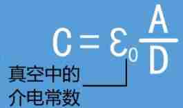
Loss rateCalculation formula :C=Q/U ( Company F/uF/nF/pF)// Q Is the charge of the monopole ,U Is the potential difference between the two plates .
Decisive :
A It's the area ,D It's distance . High school formula ,S And A It's the same .
Dielectric constant : The dielectric constant of the material makes the capacitance very small , The capacity value is quite large . ( The capacitor plate must be made of insulator )
Dielectric strength : Withstand voltage , Voltage required for breakdown .
Dielectric loss : Displacement current of polarized molecules , High frequency circuits need special attention .
Representation : The direct labeling method , Color code method
Capacitance detection : Electric bridge method , Multimeter capacitor block ;
Detection of capacitance : Turn the digital multimeter to buzzer , Use two probes to connect with the measured capacitor C The two pins of contact , A short beep should be heard , Then the sound stops , The overflow symbol is also displayed “1”. next , Adjust the two probes and measure again , The buzzer should sound again , The overflow symbol is finally displayed “1”, This situation shows that the measured electrolytic capacitor is basically normal . here , You can dial to ”20M“ or “200M” Measure the leakage resistance of the capacitor with the high resistance gear , You can judge whether it is good or bad .
Schematic representation :
Characteristics of capacitance :1) Every other day 2) The voltage on the capacitor must not jump .
The function of capacitance : Energy storage , wave filtering , Push coupling , bypass ,LC resonance .
How to choose capacitance :1. function ;2. texture of material ;3. Capacitance value , Voltage value .
inductance
What is inductance : Inductance is an attribute of closed loop , It's a physical quantity . When the current passes through the coil , Magnetic field induction is formed in the coil , The induced magnetic field will generate induced current to resist the current passing through the coil . This current is related to the coil name . It describes the change of coil current , Circuit parameters causing induced electromotive force effect in this coil or in another coil . Inductance is the general term of self inductance and mutual inductance . The device that provides inductance is called inductor .
The inductance value is the inherent attribute that leads you to dry , It has nothing to do with the frequency and current in the circuit . Only related to its composition , Similar to the concept of resistance , Independent of voltage and current , Related to material .
Generally speaking, inductance refers to inductor .
Inductor :(Inductor) It is an element that can convert electric energy into magnetic energy and store it . The structure of the inductor is similar to that of a transformer , But only one winding . Letters for inductance L Express
Characteristics of inductance : The inductor has a certain inductance , It only blocks the change of current . If the inductor is in a state where no current passes , When the circuit is connected, it will try to block the current flowing through it ; If the inductor is in a state with current passing through , When the circuit is disconnected, it will try to keep the current constant . The ideal inductance has no loss . Through DC resistance AC
Composition of inductance : Enameled wire or yarn wrapped wire Skeleton or magnetic core or iron core
The unit of inductance is H(mH uH nH) Usually, it directly indicates that the inductance is 3R3(3.3uH R The decimal point , It has nothing to do with resistance )
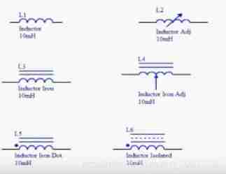
Circuit diagram representation :
Classification of inductors :Classify according to the packaging form : Chip inductors 、 Plug in inductance
By frequency : High frequency inductance 、 Intermediate frequency inductance and low frequency inductance
Classified by use : Oscillating inductance 、 Isolation inductance 、 Filter inductanceThe role of inductance :
wave filtering
The difference between inductance and capacitance
The electric induction connects the DC resistance to the AC , The current does not change suddenly ( Suitable for high current , Low voltage circuit ); Capacitance is separated by direct current , The voltage does not change suddenly ( Suitable for high voltage , A circuit with low current )
The impedance of the inductor is proportional to the frequency , The impedance of the capacitor is inversely proportional to the frequency , So inductance can suppress high-frequency passage , Capacitors can suppress low-frequency passage . A proper combination of the two , You can filter various frequency signals .
Capacitive filtering belongs to voltage filtering , It directly stores the pulsating voltage to smooth the output voltage , High output voltage , Close to AC voltage peak ; Suitable for small current , electric current The smaller the filter, the better .
Inductive filtering belongs to current filtering , By generating electromagnetic induction through current to smooth the output current , Usually the output voltage is low , Lower than the effective value of AC ; Suitable for high current , The greater the current , The better the filtering effect . Many characteristics of inductance and capacitance are exactly the opposite .Shock
The current that can produce a change in size and direction with the periodic transmission is called oscillating current , The circuit that can produce oscillating current is called oscillating circuit . The simplest oscillation circuit is called LC loopDelay
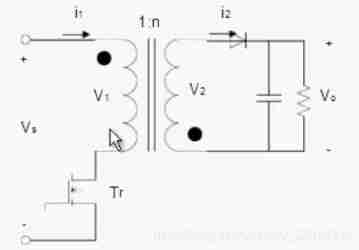
transformer : A device that uses the principle of electromagnetic induction to change AC
The main components of the transformer : Primary coil 、 Secondary coil 、 Magnetic core
Transformer principle : Turn Baidu 、 High school physics book
Applications in life : Electric welding , uhv
Classification of transformers :By use :
1、 Power transformer : It is used for power transmission and distribution system 、 Voltage drop .
2、 Instrument transformer : Such as voltage transformer 、 Current transformer 、 Used for measuring instruments and relay protection devices .
3、 Test transformer : Can produce high pressure , Conduct high voltage test on electrical equipment .
4、 Special transformer : Such as electric furnace transformer 、 Rectifier transformer 、 Adjust the transformer 、 Capacitive transformer 、 Phase shift transformer, etc .Divide according to the number of phases :
1、 Single phase transformer : For single-phase load and three-phase transformer group .
2、 Three phase transformer : Used for three-phase system 、 Voltage drop .Divide according to winding :
1、 Double winding transformer : Used to connect two voltage levels in the power system .
2、 Three winding transformer : It is generally used in regional substations of power system , Connect three voltage levels .
3、 Autotransformer : Used to connect power systems with different voltages . It can also be used as a common step-up or step-down transformer .What is high frequency transformer : The operating frequency exceeds the intermediate frequency (10kHz) Power transformer , It is mainly used in high-frequency switching power supply as high-frequency switching power transformer , It is also used in high-frequency inverter power supply and high-frequency inverter welding machine as high-frequency inverter power transformer
Flyback circuit
working principle
Several precautions and steps for winding
1) Determine the input voltage range , Calculate according to the minimum input voltage
2) Determine the output power 、 The efficiency of the circuit 、 Duty cycle 、 Switching frequency
3) Selection manual of magnetic core and enameled wire
4) The main calculation formula : Calculate the window area , Select the magnetic core ; Calculate the number of turns on the primary side ; Calculate the primary inductance ; Calculate the air gap ; Calculate the number of secondary side turns according to the turn ratio ; Calculate the current density of the secondary side ; Finally, it is calculated that the appropriate enameled wire is several strands and wound ( Consider skin effects )
Specific formula Baidu , It is not easy to knock out .
The fuse ( Fuse )
The function and working principle of Insurance : It mainly plays the role of overload protection . Place the fuse correctly in the circuit , When the current of the fuse rises abnormally to a certain height and heat , Self Fusing cut off current , It protects the safe operation of the circuit .
Classification of insuranceSort by form : Over current protection and overheat protection
Classification according to fusing speed : Very slow 、 Slow down 、 Medium speed 、 Fast 、 Very fast
According to whether to restore : Irrecoverable Insurance 、 Self recovery Insurance
Self recovery fuse : An overcurrent electronic protection component , A special material , When sending overload or short circuit , The resistance will be particularly high , Similar to open circuit .Parameters and selection of Insurance
Parameters :Voltage rating : The maximum voltage that can be borne by both ends of the disconnect fuse .
Current rating : The maximum current that the fuse can work in the working circuit .
Fusing characteristics : The fuse The time range of fusing under different overload current loads .
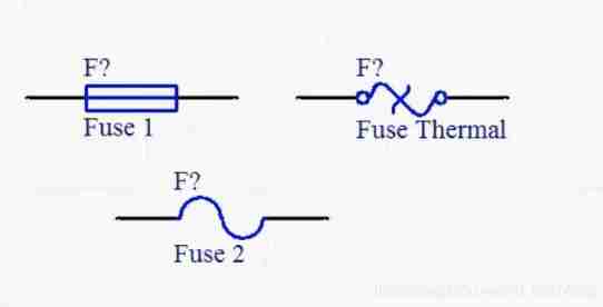
Breaking capacity : The most important indicator , Under the specified voltage , It can safely cut off the maximum current .Circuit diagram representation :
diode
Principle and characteristics of diode
Diode composition
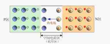
The diode is made of PN The junction is composed of a shell and leads . from p Type a semiconductors and n Type a semiconductor p-n junction , A space charge layer is formed on both sides of the interface , And build a self built electric field
working principle
When there is no applied voltage , because p-n The diffusion current caused by the carrier concentration difference on both sides of the junction is equal to the drift current caused by the self built electric field and is in the electric equilibrium state . When there is a positive voltage bias outside , The mutual suppression and elimination of external electric field and self built electric field make the diffusion current of carrier increase and cause positive current . When there is reverse voltage bias outside , The external electric field and self built electric field are further strengthened , A reverse saturation current independent of the reverse bias voltage value is formed within a certain reverse voltage range I0.
Personal understanding of diode ( Need high school physics and Structural Chemistry Foundation ):n There are free electrons in the region ,p There are holes in the area ( Empty orbit ). When it is connected , Free electrons from N==》P, It can conduct , because ,N The free electrons of the region arrive P There are holes in the region to hold these electrons . But when reverse connection ,P The free electrons of the region arrive N District ,N The free electron resistance of the region P The addition of free electrons in the region , Free electrons grab holes here , Great internal friction , It is difficult to form access .
Schematic diagram
characteristic :
Volt ampere characteristics : Analog resistance volt ampere characteristic curve . It is divided into four areas : Conduction area , dead zone , Inverse cut-off area , Reverse breakdown region ( Drive voltage : Voltage that allows the diode to work ; Reverse breakdown voltage : Let the diode lose the voltage of single continuity ;PS: Temporary , Reducing the voltage can restore .)
Temperature curve
Classification and application of diodes
classification
1. Classified according to semiconductor materials : Germanium diode 、 Silicon diodes
2. Classify according to different uses : Current detection diode 、 Rectifier diode 、 Switching diodes 、 Zener diode .
3. According to the structure of the pipe core : Point contact diode 、 Surface contact diode 、 Planar diode
4. According to the reverse recovery time of diodes : Ordinary diode and fast diode ( Schottky diode and fast recovery diode )purpose :
Ordinary diodes are often used for detection
Rectifier diode is used for power rectification
Switching diode is used in the switching circuit controlled by computer pulse
Zener diode is used in the zener circuit
Light emitting diodes such as LED diode
Point contact diode is used for detection , Frequency detection and filtering . Used in low current high frequency circuit
Surface contact diode is used for low-frequency rectifier diode
Fast diodes are used in high frequency rectifier circuits , High frequency switching power supply , High frequency resistance capacitance absorption circuit , Inverter current, etc
Parameters and type selection of diode
Parameters
1. Reverse saturated leakage current Is
2. Rated rectifier current If
3. Maximum reverse operating voltage Urm
4. Maximum working frequency fm( because pn The existence of junction capacitance , When the working frequency exceeds a certain value , Unidirectional conductivity becomes poor )
5. Reverse working time trr( Refers to when the diode suddenly reverses from conduction , The reverse current decays from very large to close to Is The time taken to )The selection : Model selection according to parameters and functions , Don't say more
Diode measurement : Use an ordinary multimeter ( No diode block ): Measure the forward and reverse resistance , If the reverse resistance is much greater than the forward resistance , No problem ; If they are equal or infinite or 0, It means that the diode is broken .
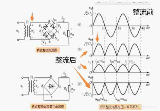
Rectifier bridge 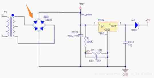
principle
Heat dissipation of rectifier bridge : Consider as appropriate
Parameters and type selection of rectifier bridge
1. Parameters of rectifier bridge : Forward current 、 Reverse withstand voltage 、 Reverse leakage current 、 Forward pressure drop
2. Selection of rectifier bridge .: voltage electric current
Application of rectifier bridge
Half-wave rectifier
Full-wave rectifier
Bridge rectifier
triode
Definition and working principle of triode
The basic definition
Semiconductor triode is also called bipolar junction transistor (BJT), It is a device with three electrodes .
Make two closely spaced on a semiconductor substrate PN junction , Two PN The junction divides the whole semiconductor into three parts , The middle part is the base area , The two sides are the launching area and the collecting area , The arrangement is PNP and NPN Two kinds of .classification
According to the structure, it can be divided into :NPN The type and PNP type
According to the material, it can be divided into : Silicon tube and germanium tube
According to the frequency, it can be divided into : High frequency tube and low frequency tube
According to the power, it can be divided into : Small power 、 Medium power 、 High Powerworking principle
myth , It can't be simply thought of as two diodes in series . You can watch this video , It's very vivid and easy to understand :B Station triode video
Triode is a very important component for weak current to control strong current , It is suggested to know more about , The author's level is limited , Dig a hole first , Update later
Characteristic curve of triode Fill the pit later
Input characteristic curve
Describe the Uce Fixed time ,Ib And Ube The functional relationship between ( Similarly, there are dead zones , Linear area , Nonlinear region )
Output characteristic curve
Describe the base current Ib Is a constant , Collector current Ic And pipe pressure will Uce Between the functions ( Divide the cut-off area , Saturation zone , Zoom in )
Parameters and packaging form of triode Fill the pit later
Parameters
1.Icm Maximum allowable collector current
2.Vceo When the base of the triode is open , Collector - Emitter reverse breakdown voltage .
3.Pcm Is the maximum allowable dissipation power of the collector
4. Characteristic frequency ftPackage form
TO-92 SOT-23 SOT-223 TO-220
Use a multimeter to judge the type and polarity of the triode
Judge collector and emitter
Still set the multimeter ohm "R X 1k" It's about , With NPN Take tube for example , Connect the red probe to the hypothetical collector c On , The black probe is connected to the hypothetical emitter e On , And hold b and c extremely ( Can't make b、c Direct contact ), Through the human body , Quite a b、c Connect the bias resistor , Read out the resistance value shown by the multimeter, and then connect the two probes reversely to retest . If the resistance value measured for the first time is smaller than that measured for the second time , Explain that the original assumption is true , because C、e The resistance between two meters indicates that the current passing through the multimeter is large , The offset is normal . The multimeter can measure the magnification of triode (Hfe) The interface of , It can be estimated that . The magnification of the lower triode .
Judge category (NPN still PNP)
Judge the base with a digital multimeter b And the type of triode : Set the multimeter ohm gear "RX 1k" It's about , Let's assume that one pole of the triode is " The base ", And connect the red lead to the hypothetical base , Connect the black probe to the other two poles successively , If the resistance value measured twice is very small ( Or about hundreds to thousands of euros ), Then the assumed base is correct , And the tested triode is NPN Type tube ; If the resistance value measured twice is very large ( About thousands of euros to tens of thousands of euros ), Then the assumed base is correct , And the tested triode is PNP Type tube . If the resistance value measured twice is one large and one small , Then the original assumed base is wrong , At this time, it must be assumed that the other electrode is " The base ", Repeat the above test .
Amplification circuit of triode
Common base circuit
Common emitter circuit
Common collector circuit
Function and application of triode
Current amplification
Control switch
Steady pressure
Connector
Connector 、 The essence of keys and dialing switches
All three belong to electronic connectors
A conductor device that connects electrical circuits
It can be used as a circuit room , Between components , Electrical between systems 、 Electronic transmission connecting parts , Make the power , The signal , Current can flow stably and reliably , It is also convenient for product assembly , Repair and replacement .
Connector
function : Connect two active devices , Transmit power and signals
Basic performanceMechanical properties : Plugging force
Electrical performance : Foundation resistance , Insulation resistance , Electrical strength ( Withstand voltage value )
Environmental performance :advantage : Easy disassembly and maintenance
Classification and selectionClassified by shape : Circular cross section and rectangular cross section
By frequency : High frequency and low frequency
It can also be used according to the purpose or PCB Classification of welding methods
Key
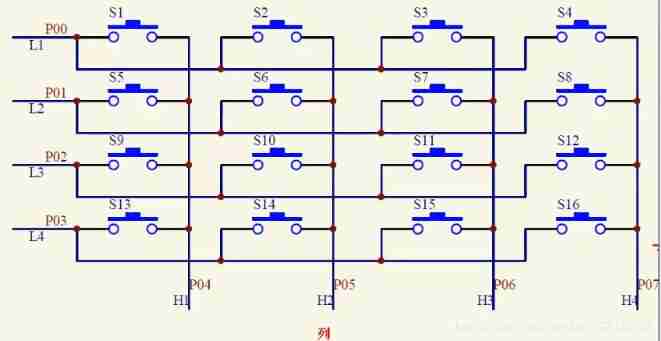
Keys are the most common input and output components in the smallest system composed of single chip computers , Especially in the realization of human-computer interaction function . Press the key circuit , One cannot be divided into two types: one-to-one direct connection and dynamic scanning matrix connection .
Independent buttons : One key occupies a separate I/O mouth . Its work is not affected by other buttons and I/O Influence . A single key can also be called an independent key . Keys with different functions can also be called independent keys
Matrix keyboard : To save I/O mouth , The keys are usually arranged in a matrix form , Each horizontal and vertical line is not directly connected at the intersection , It is linked by a button .Matrix key principle
Dial switch
Dial switch ( Also called DIP switch , Toggle switch , Overclocking switch , Address switch , Pull the switch , Digital switch , Dial switch ) It is an address switch used to operate and control , use 0/1 Binary coding principle
principle : There are two pins on the back of each key , Dial to ON One side , The next two pins are connected ; On the contrary, disconnect . This key is independent , There's no connection . Such components are mostly used for binary coding .
effect : Widely used in data processing 、 signal communication 、 On a series of products that need manual programming, such as remote control and anti-theft automatic alarm system .
classification : Evenly distributed 、 Keyboard type 、 Right angle type 、 Patch type 、IC type .
Buzzer
The buzzer is an integrated electronic sounder , It is a kind of pronunciation device that can convert audio signal into sound signal . Using DC voltage supply , It is widely used in electronic products as generating devices .
The buzzer has letters in the circuit “H” or “HA”( Old standard “FM”、“ZZG”、“LB”、“JD” etc. ) Express
classification
Buzzer can be divided into piezoelectric buzzer and electromagnetic buzzer .
It can also be divided into active buzzer and passive buzzer ( The source refers to the oscillating source , It's not the power supply )Piezoelectric buzzer : Paste the piezoelectric material on the metal sheet , When a voltage is applied to both ends of the piezoelectric material and the metal sheet , Because of the piezoelectric effect , The buzzer will produce mechanical deformation and make a sound .
Piezoelectric buzzer is mainly composed of multivibrator 、 Piezoelectric buzzer 、 Impedance matchers and resonators 、 Shell, etc . Some piezoelectric buzzer shell is also equipped with light-emitting diodes . A multivibrator consists of a transistor or an integrated circuit . When the power is on (1.5~15V DC operating voltage ) , The multivibrator starts , Output 1.5~2.5kHZ The audio signal , The impedance matching device pushes the piezoelectric buzzer to sound .
Piezoelectric buzzer has small volume 、 High sensitivity 、 Save electricity 、 Good reliability , Low cost and good frequency characteristics . The most common is music greeting card 、 digital watch 、 Pocket calculator 、 Electronic doorbells, electronic toys and other small electronic products are used as sound producing devices .Electromagnetic buzzer : Electromagnetic buzzer is an electronic buzzer that uses the effect of electromagnetic coil on buzzer to make sound. It is used to make sound devices for electronic products .
difference :
There are two types of buzzers: piezoelectric and electromagnetic :
Piezoelectric buzzer is based on the piezoelectric effect of piezoelectric ceramics , To drive the metal sheet to vibrate and make sound ;
Electromagnetic buzzer , It uses the principle of electromagnetism , When power is on, the metal vibrating film is sucked down , When it is not electrified, it will spring back according to the elastic force of the vibrating membrane ,
Therefore, the piezoelectric buzzer is driven by square wave , The electromagnetic type is 1/2 Square wave drive , Piezoelectric buzzer needs relatively high voltage to have enough sound voltage , The general suggestion is 9V above . Some specifications of piezoelectric , You can achieve 120dB With On , Larger sizes are also easy to reach 100dB.
Electromagnetic buzzer : use 1.5V You can send out 85dB The above sound pressure , Only the current consumption will be much higher than that of piezoelectric buzzer , And in the same size , Electromagnetic buzzer , The response frequency can be relatively low ; Sound pressure of electromagnetic buzzer - At most 90dB . Mechanical buzzer is a small category of electromagnetic buzzer .Active buzzer : There is an oscillation source inside , It will sound when powered on
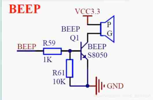
STM32 The hardware circuit of buzzer : BEEP Pick up STM32 IO, adopt R59, Power triode S8050 The base of b High level , The emitter e Grounding ,be The knot will turn on ; Collector c Connect the load, connect VCC3.3V,bc junction , It will also turn on ,NPN triode , It is in a saturated state .R59 The function of is to limit current , Reduce IO Port output current ; and R61 Is to prevent IO Floating in the air , Buzzer blaring .
Schematic diagramPassive buzzer : No internal oscillation source , If you can't make it beep with DC signal , Must use 2~5k To drive it .
Classification of buzzers
Visual measurement :
Look up the table :
Measure with a multimeterUse a multimeter to measure the resistance Rxl Gear test : Connect the black probe to the buzzer "+" Pin , Touch the red lead back and forth on the other pin , If it triggers a click 、 Click and the resistance is only 82( or 168 ) It's a passive buzzer ; If you can make a continuous sound , And the resistance is more than several hundred ohms , It's an active buzzer .
DC voltage test
commonly 12MM The general voltage of passive is 1. 5V, The general voltage of active electromagnetic buzzer is 1.5,3.0,5.0,9.0, 12V, Input the corresponding voltage with DC voltage ( From minor to major ), The frequency is about 2.7KHZ, Can ring directly for the active electromagnetic buzzer , It doesn't ring directly , It is a passive electromagnetic buzzer that needs square wave to drive .
IGBT
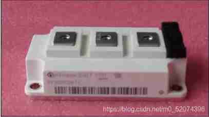
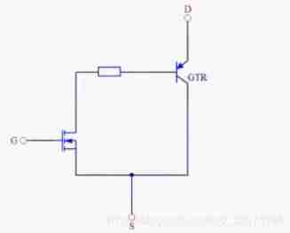
IGBT: Insulated gate bipolar transistor , It is composed of triode and MOS( Insulated gate FET ) Composite fully controlled voltage driven power semiconductor device , Both MOSFET High input impedance and triode Low conduction voltage drop .
characteristic
IGBT It combines the advantages of the above two devices :
High input impedance , Low conduction voltage drop ;
Voltage control , Low driving power , Fast switching speed ;
Work efficiency can reach 10~40KHz ( Higher than power triode ) ;
The saturation pressure decreases ( Than MOSFET Much smaller , Equivalent to power triode ) ;
voltage 、 The current capacity is large , The safe working area is wide .
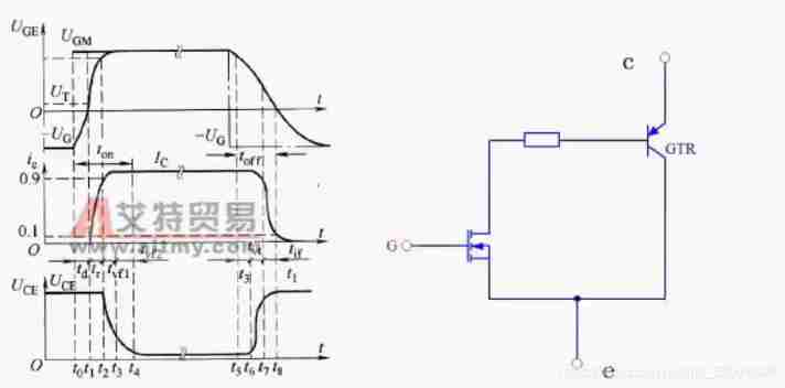
It is very suitable for applications where the DC voltage is 600V And above, such as AC motor 、 Frequency converter 、 Switching Mode Power Supply 、 Lighting circuit 、 Traction transmission and other fields .structure :IGBT In order to GTR Main guide ,MOSFET It is a composite structure of driving parts
notes :GTR It's one of the triodes - Kind of ,Giant Transistor, Giant transistors can work at high voltage 、 Under high current , Also known as power transistor .
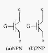
Symbol :
working principle
If in IGBT A positive driving voltage is applied between the grid and the emitter of , be MOSFET Conduction , such PNP The low resistance state between the collector and the base of the transistor makes the transistor turn on ; if IGBT The voltage between the grid and emitter of is 0V, be MOSFET end , Cut off the PNP Supply of transistor base current , Make the transistor cut off .
Safety and reliabilityIGBT Voltage between grid and emitter ;
IGBT Voltage between collector and emitter ;
Flow through IGBT Collector Emitter Current ;
IGBT Junction temperature
If IGBT Voltage between grid and emitter , That is, the driving voltage is too low , be IGBT Can't work stably and normally , If it is too high and exceeds the withstand voltage between grid and emitter IGBT Possible permanent damage ; Again , If added to IGBT The allowable voltage between collector and emitter exceeds the withstand voltage between collector and emitter , Flow through IGBT The current of Collector Emitter exceeds the maximum current allowed by Collector Emitter ,IGBT The junction temperature of exceeds its allowable value ,IGBT May be permanently damaged .
Working characteristics
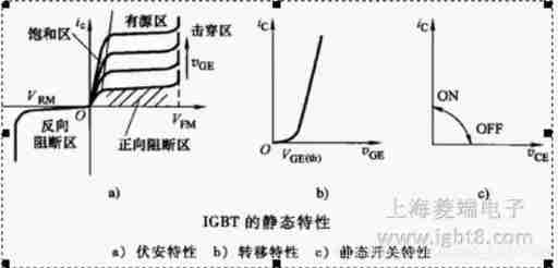
static characteristic
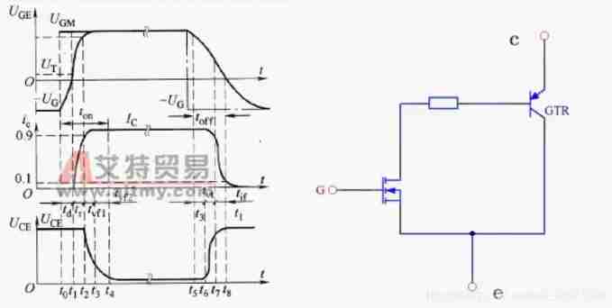
A: Volt ampere characteristics ( output characteristic ): Ic=f (Uce).IGBT The volt ampere characteristics of are shown in the figure below a) Shown , And GTR The volt ampere characteristics of are basically similar , The difference is , The control parameter is grid source voltage , Not the base shenliu .
B: Transfer characteristics : IGBT The transfer characteristics of MOS The transfer characteristics of the tubes are the same ,Ic=f (Uge)
C: Static switching characteristics : When the gate source voltage is greater than the threshold voltage ,IGBT Namely conduction . The characteristics are shown in the figure C
Dynamic characteristics :IGBT The dynamic characteristic of refers to IGBT Characteristics during switching , Including the opening process , Shutdown process and holding effect .
Opening process :
IGBT Open Communication process and power MOSFET The opening process of is similar , This is because IGBT Most of the time in the opening process is as power MOSFET Running . The opening time is from 4 Part of it is made up of : One is to apply grid pulse from outside UGM Jump from negative to positive , To grid one - The radio voltage is charged to UT Time for ( Corresponding t1-t0) The opening delay time td. The other is that the collector current starts from zero , Rise to 90% Time of steady-state value (t2-t1) , Weigh the current rise time tr. During these two periods , Collect the voltage between one emitter UCE Basically unchanged .f=t2 in the future , Set - Emitter voltage UCE Start to fall ,UCE The descending process of is divided into tvf1 and tvf2 Two paragraphs . Descent time tvf1 yes MOSFET Working alone - Emitter voltage drop time (t3-t2) ,tvf2 It's power MOSFET and PNP When transistors work at the same time - Emitter voltage drop time (t3-t4) , because UCE When it comes down ,IGBT Medium power MOSFET Grid 、 Leakage capacitance increases , and IGBT Medium PNP It also takes a process for transistors to change from amplified state to saturated state , therefore tvf2 The voltage drop process of the section slows down . Only in tvf At the end of the paragraph ,IGBT Before it fully enters the saturation state . therefore , Always open Time ton=td+tr+tvf1+fvf2.
Parameters haveOpening delay time td (on);
Current rise time tr;
Opening time ton;
tfv1 MOSFET Voltage drop process when working alone ;
tfv2 MOSFET And PNP crystal Voltage drop process when the body tube works at the same time ;
Turn off the process
Apply a reverse pulse voltage to the grid -UGM, Under the action of this reverse voltage , Internal equivalence MOSFET Input capacitor discharge , Internal equivalence GTR Still on ,t5~t6 Within time , Collector current 、 There is no obvious change in voltage , This period of time is defined as the storage time ts.t6 After the moment ,MOSFET Start to exit saturation , The device voltage rises ,PNP The collector current of the tube has no obvious change .t7 moment UCE. Rise to near UCM, t6~t7 This period is called voltage rise time tvr. after , power MOSFET Exit saturation GTR The base current drops , The collector current decreases , From grid voltage +UGE The trailing edge of the pulse drops to its amplitude 90% From the moment of , The current to the collector drops to 90% ICM stop ( about t5^ t7), This period of time is the shutdown delay time td(off). thereafter ,UGE Continue to decay , To t8 moment ,UGE Down to UT,MOSFET Turn off , PNP The base current of the tube is zero , The collector current drops to close to zero . Collector current from 90%ICMT Down to 10%ICM This period of time is the current drop time tif. It will take some time to eliminate the stored charge inside the transistor , therefore f= t8 There is another tail time in the future tt, In this period of time , Because set - Emitter voltage has been established , There will be large losses . Definition t5~t8 This period is the off time toff, namely toff=td(I)+tif=ts+tvf+tif.IGBT Internal due to bipolar PNP The existence of transistors , The flow capacity is increased 、 The withstand voltage of the device is improved 、 Benefits such as reduced on state voltage drop of devices , However, due to the emergence of minority carrier storage , bring IGBT Switching speed specific power MOSFET The speed should be low .
Parameters haveTurn off delay time td (off)
Current up and down time tr
Off time toff
tfil MOSFET During shutdown Ic Rapid decline
tfi2 PNP The transistor is turning off Ic The decline is slow
Hold effect :IGBT A phenomenon out of control
if Ic The moment is too big , Even if you remove Uge,IGBT It will be like The thyristor is also conductive , send G Pole lost control , This effect is called the hold effect .
The selection
Voltage specifications
Current specification
Circuit structure
encapsulation
Circuit design considerations
Drive circuit
Grid protection circuit
Overload protection :1.2~1.5 Times overload protection
For overload protection, there is no need to respond quickly , Centralized protection can be adopted , That is to detect the total current of the input terminal or DC link , At this point, the current exceeds the set value The rear comparator flips , Block all IGBT Input pulse of the driver , Make the output current drop to 0. Once this kind of action, it can resume normal work through reset .
Short circuit protection :(8~ 10 times ) Short circuit protection
Over voltage protection : Drive circuit and control circuit shall be electrically isolated , Consider the electrical clearance according to the voltage level , Isolation with insufficient design margin will damage the drive circuit .
Temperature protection :IGBT The maximum working temperature of depends on the maximum allowed junction temperature , Heat dissipation design must be done at this temperature
Electrostatic protection
because IGBT The module is MOS structure , Pay great attention to static electricity .IGBT Of Vge The guaranteed value of is plus or minus 20V, Apply a voltage that exceeds the guaranteed value to the module , Danger of damage . So at the grid - The voltage between emitters shall not exceed the guaranteed value .1) When using modules , When holding sub assemblies , Do not touch the drive terminal .
2) When connecting the module of the drive terminal with conductive material , Before wiring is laid , Please do not connect the module
Try to operate when the base plate is well grounded .
When it is necessary to touch the module terminals , First discharge the static electricity on the human body or clothes , Touch again .
When welding , Leakage between welding machine and welding groove is easy to cause static voltage , In order to prevent the generation of static electricity , Please keep the welding machine in a good grounding state .
Containers for parts , Please choose containers without static electricity .PS: Attention should be paid to parallel connection
It is used in large capacity inverter and other occasions to control large current IGBT When the module , Multiple devices can be used in parallel
In parallel , It is very important to make every device flow an equal current , Once the current balance is broken , Then the device with too much electricity may be damaged . In order to balance the current in parallel , Properly change the characteristics and wiring method of the device . for example : Select the device VCE(sat) The same parallel connection is very important .
Application field
GBT At the beginning of development, it was mainly used in motor 、 converter ( inverter )、 Frequency converter 、UPS、EPS Power Supply 、 Wind power generation equipment and other industrial control fields .IGBT With voltage control 、 The drive is simple , High switching frequency 、 Low switching loss , Short circuit protection and other advantages can be realized in 600V And above, the competitiveness in the medium voltage application field gradually appears , stay UPS、 Switching Mode Power Supply 、 Tram 、 AC motor control has been gradually replaced GTO、GTR.
IGBT The application in automobile mainly focuses on automobile igniter , It has successfully replaced Darlington tube as the first choice of automotive igniters . Flying omen 、 Ying Feiling 、ST It has strong competitiveness in this market .
The development of China's railway cannot be separated from a large number of electric locomotives and high-speed multiple units , Electric locomotives need 500 individual IGBT, Multiple units need more than 100 individual IGBT, A subway needs 50~80 individual IGBT modular . It is roughly estimated that the above rail transit market is beneficial to IGBT The demand for modules will exceed 3 Million , It is conceivable that rail transit will give IGBT Unprecedented opportunities and development space brought by the market .
Development trend : IGBTModule development trend is high voltage 、 High current 、 high velocity 、 Low pressure drop 、 Highly reliable 、 Low cost oriented , In particular, the development of high-voltage inverter applications , Simplify its main circuit , Reduce the use of devices , Improve reliability , Reduce manufacturing costs , Simplify debugging work , Both with IGBT There is a close internal connection .
market
At present, it is popular in the market IGBT The main brands of the module are Infineon ( Siemens 、 OPEC )、 Ximenkang 、 Mitsubishi 、 Fuji 、SPN、ON、 Fairy boy 、 Dongyi 、 Sanken 、 Third commune 、IR、ABB、DW、KEC etc.
Power converter
purpose
Used to convert voltage value , Convert high voltage to low voltage or convert low voltage to high voltage .
For voltage stabilization , Make the output voltage value stable , Suitable for SCM or PCB Use elsewhere on the board .
Used to isolate , In some circuits that need isolation , Play the role of isolation .
Convert positive and negative voltage , Convert the positive voltage into negative voltage to supply power to the circuit board .
Power converter
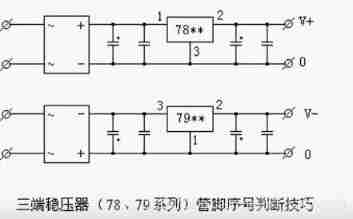
Here we mainly introduce 78XX/79XX Series of three terminal regulators
effect : Change the voltage 、 Steady pressure
The three terminal voltage stabilizing integrated circuit often seen in electronic products has positive voltage output 78Xx Series and negative voltage output 79X X series . It's called Siyi , Three ends IC It means that the integrated circuit used for voltage stabilization has only three bows | Foot output , They are inputs 、 Ground terminal and output terminal .
use 78/79 Series three terminal voltage stabilization IC There are few peripheral components needed to form a regulated power supply , There is also a protection circuit inside the circuit that flows through the heat and regulating tube , Reliable to use 、 convenient , And it's cheap . This series integrates voltage stabilization IC In the model 78 or 79 The following numbers represent the output voltage of the three terminal integrated voltage stabilizing circuit , Such as 7806 Express ; The output voltage is positive 6V,7909 Indicates that the output voltage is negative 9V.
Pay attention to the input of the three terminal integrated voltage stabilizing circuit 、 The output and grounding terminals must not be connected incorrectly , Otherwise, it is easy to burn . The minimum input of general three terminal integrated voltage stabilizing circuit 、 The output voltage difference is about 2V, Otherwise, stable voltage cannot be output , Generally, the voltage difference should be kept at 4- 5V, That is, the transformer transforms the voltage , Diode rectifier , The filtered voltage of the capacitor should be higher than the stabilized voltage
in application , Voltage stabilization shall be integrated at three ends Install a large enough radiator on the circuit ( Of course, under the condition of low power, there is no need ). When the temperature of the stabilizer tube is too high , The voltage stabilization performance will become worse , Even damage .
tips: The radiator is always with the lowest potential bow | Feet connected . In this way 78 In the series , The heat sink is connected with the ground , And in the 79 In the series , The heat sink is connected with the input end. When the production requires an output 1.5A Regulated power supply for above current , Usually, several three terminal voltage stabilizing circuits are connected in parallel , The maximum output current is N individual 1.5A.
Isolated power conversion
effect : Isolation 、 Voltage conversion 、 Steady pressure
give an example : Commonly used are Jinsheng power module 、 Zhou Ligong power module
advantage : Packaging diversity , Easy to use , Efficient , Small volume , High reliability , Good isolation effect , It has multiple protection functions , Wide application
example
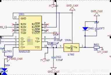
78 series
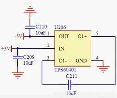
Negative voltage conversion chip
Crystal oscillator
What is Jingzhen
Crystal oscillator uses a kind of crystal which can transform electric energy and mechanical energy to work in resonance state , To provide stability , Precise single frequency oscillation . Under normal working conditions , The absolute accuracy of ordinary crystal frequency can reach 50 parts per million . Higher precision . Some crystal oscillators can also be adjusted by the applied voltage in a certain range , It's called a VCO (VCO).
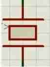
Circuit identification
application
Universal crystal oscillator , Used in various circuits , Generate oscillation frequency .
Quartz crystal resonator for clock pulse , Cooperate with other components to generate standard pulse signals , Widely used in digital circuits .
Quartz crystal resonator for microprocessor .
Quartz crystal oscillator for clocks .
The role of crystal oscillator in MCU
The function of crystal oscillator is to provide basic clock signal for the system . Usually - One system shares one crystal oscillator , To keep the parts in sync . Some communication systems use different crystal oscillators for their fundamental and RF frequencies , And keep it in sync by electronically adjusting the frequency .
Crystal oscillator is usually used with PLL circuit , To provide the clock frequency required by the system . If different subsystems need different frequency clock signals , It can be provided by different PLLs connected to the same crystal oscillator .
The difference between active and passive crystal oscillator
Passive crystal
Passive crystals need Use the oscillator in the MCU [ stay datasheet There are suggested connection methods on . Passive crystals have no voltage problem , The signal level is variable , In other words, it is determined according to the starting circuit , The same crystal can be applied to a variety of voltages , It can be used for a variety of microcontrollers with different clock signal voltage requirements, and the price is usually low , So for - For general applications, if conditions permit, it is recommended to use crystals , This is especially suitable for producers with rich product lines and large quantities . Compared with crystal oscillator, the defect of passive crystal is poor signal quality , It is usually necessary to match the peripheral circuits precisely ( Capacitors for signal matching 、 inductance 、 Resistance, etc ), When replacing crystals with different frequencies, the peripheral configuration circuit needs to be adjusted accordingly . It is suggested to use quartz crystal with high precision , Try not to use ceramics with low precision .
Active crystal oscillator
The active crystal oscillator does not need the internal oscillator of the MCU , Good signal quality , More stable , And the connection method is relatively simple ( Mainly do a good job in power filtering , Usually one by one Capacitance and inductance PI Type filter network , Output with a small resistance filter signal can be ), There is no need for complex configuration circuits . Common usage of active crystal oscillator : One foot in the air , Two feet grounded , Tripod output , Four pin voltage . Compared with passive crystal, the defect of active crystal oscillator is that its signal level is fixed , You need to choose the appropriate output level , Poor flexibility , And the price is high . For timing sensitive applications , Personally, I think active crystal oscillator is better , Because you can choose a more precise crystal oscillator , Even high-end temperature compensated crystal oscillator . Some microcontrollers have no internal vibration circuit , Only active crystal oscillators can be used , Such as TI Of 6000 Series etc. . The active crystal oscillator is usually larger than the passive crystal , But now many active crystal oscillators are surface mounted , The volume is equivalent to that of crystal , Some are even smaller than many crystals .
Precautions for crystal oscillator circuit design
1、 The singlechip that needs frequency doubling needs to be configured PLL Peripheral configuration circuit , Mainly isolation and filtering ;
2、20MHz The following crystal oscillators are basically devices with fundamental frequency , Good stability ,20MHz Most of the above are harmonic ( Such as 3 Subharmonic quilt 、5 Subharmonic, etc ), Poor stability , Therefore, it is strongly recommended to use low-frequency devices , After all, frequency doubling is used PLL The peripheral configuration required by the circuit is mainly capacitance 、 resistance 、 inductance , Its stability and price are far better than crystal oscillator devices ;
3、 The clock signal routing length should be as short as possible , The line width should be as large as possible , The distance from other printed lines shall be as large as possible , Layout and wiring close to the device , If necessary, you can use the inner layer , And surround with ground wire ; When a very low current passes through IC Crystal oscillator , If the line is too long , Will make it right EMC、ESD Very sensitive to crosstalk . Moreover, the long line will add parasitic capacitance to the oscillator .
How to judge the quality of crystal oscillator
1、 Use a digital capacitance meter ( Or the capacitance of a digital multimeter ) Measure its capacitance , Generally, the capacity of damaged crystal oscillator is significantly reduced ( The normal capacity of different crystal oscillators has a certain range , It can be measured to get , Generally in dozens to hundreds PF.
2、 Close to your ear and gently shake , If there is a sound, it must be bad ( The crystal inside has broken , If you can still use it, the frequency also changes ).
3、 Test the output pin voltage . Normally , About half of the power supply voltage . Because the output is a sine wave ( The peak to peak value is close to the source voltage ), When testing with a multimeter , It's almost half .
The crystal oscillator can't vibrate and troubleshoot
1. PCB Whether the wiring is wrong ( Eliminate the problem of MCU )
2. Whether the load capacitance and matching capacitance match the crystal oscillator , Is there a problem with the capacitance , Try changing the capacitor
3. Is the wiring too long , There is interference . Or whether there is wiring between the two pins of the crystal oscillator . The routing should be as short as possible , Avoid wiring between two pins
4. There is no interference from peripheral circuits
Relay
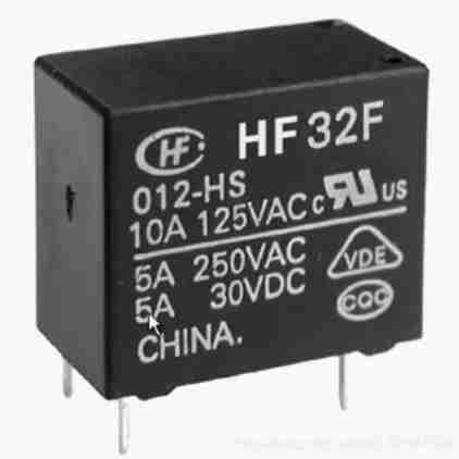
Working principle and function of relay
A relay is an electrical control device , It's when the input is ( Incentive quantity ) When the change of the system meets the specified requirements , An electrical device in an electrical output circuit that causes a predetermined step change in the controlled quantity . It has a control system ( Also called input loop ) And the controlled system ( Also called output loop ) The interaction between . It is usually used in automatic control circuits , In fact, it uses small current to control the operation of large current - Kind of “ Automatic switch ”. So in the circuit plays an automatic adjustment 、 safeguard 、 Conversion circuit, etc .
Working principle of electromagnetic relay
Working principle analysis link
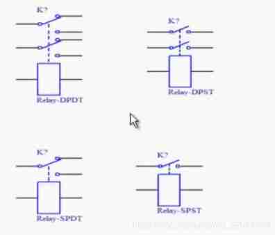
Representation
Contact form : Normally open , Normally closed , Transformational
effect
The relay has the following functions :
1) Expand the scope of control : for example , When the control signal of multi contact relay reaches a certain value , It can be in different forms of contact groups , Simultaneous connection 、 Disconnect 、 Turn on the multiplex circuit .
2) Zoom in : for example , Sensitive relay 、 Intermediate relay, etc , With a very small amount of control , A circuit that can control a large amount of power .
3) Integrated signal : for example , When multiple control signals are input to the multi winding relay in the specified form , After comparison and synthesis , Achieve the predetermined control effect .
4) Automatically 、 remote control 、 monitoring : for example , The relay on the automatic device works with other electrical appliances , It can form a program control circuit , So as to realize automatic operation .
Relay classification
According to the action principle , Relays can be divided into : Electromagnetic 、 Inductive 、 Electronic type 、 Thermal effect 、 Pneumatic type and electric motor type . The most commonly used is electromagnetic relay , It is based on the suction bow | The action depends on the amount of current in the coil .
Relays are divided into AC and DC ; The DC controlled suction coil is called DC relay : The suction coil adopts AC control, which is called AC relay .
There are many kinds of relays used in the control system , Voltage and current relays are often used , Time relay and intermediate relay .
Introduction to common relays
Voltage and current relay
Current relay is a relay that reflects the change of current , Its suction coil turns less , The wire diameter is thick . Can pass through a large current , When in use, it is connected in series with the load .
Voltage relay is a relay that reflects the change of voltage , Its suction coil has many turns , Fine wire diameter . When in use, it is connected in parallel with the power supply .
The input signal of the voltage relay coil is a relatively constant voltage value , Generally, the power supply voltage is directly added to the coil or distributed to it through the network with a constant voltage value . therefore , The loop current mainly depends on the coil impedance , Generally, other circuit elements are not involved . In order to minimize its shunting effect on other branches , Generally, the conductor is thin , More turns , Both inductance and resistance are large , The coil current is not large .
In terms of working principle , Both belong to electromagnetic relay , It doesn't make any difference . But in terms of relay design , There is a difference between them .
The magnetic circuit system of current relay is designed according to IW=C To consider , That is, when the coil inductance changes due to the action of armature during the action of relay , It will not affect the loop current value . The current is determined by the larger impedance of other circuit elements in the circuit , The influence of coil impedance of current relay on the impedance of the whole loop can be ignored . therefore , Generally, the coil wire turns of current relay are less , Inductance and resistance are small , Therefore, the coil current is large . The current supplied to the coil of the current relay is a constant current value .
The input signal of the voltage relay coil is a relatively constant voltage value , Generally, the power supply voltage is directly added to the coil or distributed to it through the network with a constant voltage value . therefore , The loop current mainly depends on the coil impedance , Generally, other circuit elements are not involved . In order to minimize its shunting effect on other branches , Generally, the conductor is thin , More turns , Both inductance and resistance are large , The coil current is not large .
Current relay is a kind of electrical device used to protect electrical equipment or motor from over-current and under current . Connect the current relay coil in series in the main circuit , Sense the working current of the main circuit , The setting value of overcurrent parameters of current relay is generally... Of the rated current of the protected line 1.1——4 times . When the current in the protected line is normal , The armature does not act , The current in the protected line is higher than the rated value , When the setting value of overcurrent relay is reached , The armature is engaged , The contact mechanism acts , Normally open and normally closed contacts output corresponding control signals , So as to achieve the role of protection .
The setting value of under current parameter of current relay is generally that the attracting current is... Of the rated current of coil 30%——65%, The release current is... Of the rated current 10%——20%, therefore , When the circuit is working normally , The armature is engaged , Only when the current decreases to a certain setting value , Armature release , The contact mechanism acts , Normally open and normally closed contacts output corresponding control signals , So as to achieve the role of protection . Voltage relay is a kind of electrical device used to protect electrical equipment or motor from overvoltage and undervoltage . Connect the voltage relay coil in parallel in the main circuit , Sense the line voltage of the main circuit , The overvoltage parameter setting value of voltage relay is generally... Of the rated voltage of the protected line 1.05——1.2 times . When the voltage of the protected line is normal , The armature does not act , The voltage of the protected line is higher than the rated value , When the setting value of overvoltage relay is reached , The armature is engaged , The contact mechanism acts , Normally open and normally closed contacts output corresponding control signals , So as to achieve the role of protection .
The undervoltage parameter setting value of voltage relay is generally... Of the rated voltage of the protected line 0.1——0.6 times . When the voltage of the protected line is normal , The armature is reliably engaged , When the voltage of the protected line drops to the release setting value of the undervoltage relay , Armature release , Reset the contact mechanism , Normally open and normally closed contacts reset , So as to achieve the role of protection .
Time relay
In the control line , In order to achieve the order of control , Improve the purpose of protection , It needs to be that the action of some devices has a certain delay .
The characteristic of time relay is that when the control signal is received , For example, the relay coil turns on or off the power , Its contact state does not change immediately , But after a time delay , Electric shock will make or break , Therefore, it is also called time delay relay .
Intermediate relay
Intermediate relay has cross 、 DC two , The intermediate relay is characterized by a large number of contacts , Generally in 3-3 To the above , Bridge type contacts are often used in the form of electric shock ( Same as auxiliary contact of contactor ). The structure of the intermediate relay with large action power is the same as that of the small contactor .
Logic circuit can be realized by relay " And "、” or “、" Not ”
And: And operation . It is true only when both are true , Similar to multiplication .
Or: Or operations . It is false only when both are false , Similar to addition .
Xor: Exclusive or operation . Same as false , Different is true .
Optocoupler
Optical coupler (opticalcoupler, The abbreviation is OC) Also known as photoelectric isolator or photoelectric coupler , Optocoupler for short . It is a device that uses light as the medium to transmit electrical signals , Usually put the illuminator ( Infrared light emitting diode LED) And light receiver ( Photosensitive semiconductor tube ) Encapsulated in the same shell . When an electrical signal is applied to the input, the light emitter emits light , After receiving light, the light receiver generates photocurrent , From the output , So that “ electric - light - electric ” transformation . The output end of the optocoupler is used as the input end of the optocoupler , Because of its small size 、 Long life 、 Contactless , Strong anti-interference ability , Insulation between output and input , Unidirectional signal transmission and other advantages , In digital circuits . Has been widely used .
Circuit model diagram
There are two types of optocouplers : One is nonlinear optocoupler , The other is linear optocoupler .
frequently-used 4N Series optocoupler belongs to nonlinear optocoupler , The commonly used linear optocoupler is PC817A-C series .
The current transmission characteristic curve of nonlinear optocoupler is nonlinear , This kind of optocoupler is suitable for switching signal transmission , It is not suitable for transmitting analog quantity .
The current transmission characteristic curve of the linear optocoupler is connected into a straight line , And the performance is better when the signal is small , It can perform isolation control with linear characteristics . The commonly used optocoupler in switching power supply is linear optocoupler . If a nonlinear optocoupler is used , It is possible to deteriorate the oscillation waveform , Parasitic oscillation occurs in severe cases .
Optocoupler parameters
Forward current IF: The current flowing through the diode when a certain forward voltage is applied at both ends of the tube under test .
Reverse current IR: Apply the specified reverse working voltage at both ends of the tested tube VR when , The current flowing through the diode .
Reverse breakdown voltage VBR: The reverse current passed by the tested tube IR When it is the specified value , The voltage drop between the two poles .
Junction capacitance CJ: Under the specified bias voltage , Capacitance value at both ends of the tested tube .
Reverse breakdown voltage V(BR)CEO: Light emitting diode The pole tube is open , Collector current IC Is the specified value , Voltage drop between collector and emitter .
Output saturation voltage drop VCE(sat): Working current of LED IF And collector current IC When it is the specified value , And keep IC/IF≤CTRmin when (CTRmin When the value is specified in the technical conditions of the tested pipe , The current flowing through the collector is the reverse cut-off current .
Current transfer ratio CTR: When the working voltage of the output tube is the specified value , The ratio of the output current to the forward current of the LED is the current transmission ratio CTR ( Gain of optocoupler ).
Besides , When transmitting digital signals, it is also necessary to consider the rise time 、 Descent time 、 Parameters such as delay time and storage time .
tips: Current transfer ratio is an important parameter of optocoupler , Usually expressed by DC current transmission ratio . When the output voltage remains constant , It is equal to the DC output current IC And DC input current IF Percent of . Optocoupler using a photosensitive triode ,CTR The scope of is mostly 20% ~ 300%( Such as 4N35), and pc817 Then for 80%~ 160%, Such as EL817 Can be up to 50%~ 600%. This indicates that you want to obtain the same output current , The latter requires only a small input current . therefore ,CTR The parameters are the same as those of the transistor hFE There is a certain similarity .
Selection principle of linear optocoupler
In the isolation of switching power supply , And when designing optocoupler feedback switching power supply, we must correctly select the model and parameters of linear optocoupler , In addition to following the selection principle of ordinary optocoupler , The following principles must also be followed :
1、 Linear optical coupler is recommended , Its characteristics are CTR The value can be in one - Make linear adjustment within a certain range
2、 Current transmission ratio of optocoupler (CTR) The allowable range of is 50%~ 200%. This is because when CTR<50% when , In optocoupler LED Large working current is required (IF> 5.0mA), In order to normally control the single-chip switching power supply IC Duty cycle of , This will increase the power consumption of the optocoupler . if CTR> 200%, When starting the circuit or when the load changes , It is possible to trigger the monolithic switching power supply by mistake , Affect normal output .
3、 If amplifier circuit is used to Drive Optocoupler , Must be carefully designed , Ensure that it can compensate the temperature instability and drift of the coupler .
Tips for using optocoupler
Optocoupler takes optical signal as the medium to realize the coupling and transmission of electrical signal , Input and output are completely electrically isolated , It has strong anti-interference performance . For both weak current control part , It also includes the industrial application measurement and control system of the strong current control part , Using optocoupler isolation can well realize the isolation of weak current and strong current , Achieve the purpose of anti-interference . however , The following issues need to be considered when using optocoupler isolation :
① When the optocoupler is directly used to isolate and transmit analog quantity , Consider the nonlinearity of the optocoupler ;
② When the optocoupler transmits digital quantity in isolation , Consider the response speed of the optocoupler ;
③ If the output has power requirements , The power interface design of the optocoupler must also be considered .
Overcoming nonlinearity of optocoupler
The input end of the optocoupler is a light-emitting diode , therefore , Its input characteristics can be expressed by the volt ampere characteristics of light-emitting diodes , Pictured b Shown ; The output end is a photosensitive triode , Therefore, the volt ampere characteristic of photosensitive triode is its output characteristic , Pictured c Shown . The figure is visible , There is a nonlinear working region in the optocoupler , When it is directly used to transmit analog quantity, the accuracy is poor .
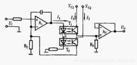
utilize 2 Optocouplers with the same nonlinear transmission characteristics ,T1 and T2, as well as 2 Emitter follower A1 and A2 form , As shown in the figure below . If T1 and T2 They are optocouplers of the same model and batch , It can be considered that their nonlinear transmission characteristics are completely consistent , namely K1(I1)=K2(I1), Then the voltage gain of the amplifier G=Uo/U1=I3R3/I2R2= (R3/R2)[K1(I1 )/K2(I1)]=R3/R2. thus it can be seen , utilize T1 and T2 Symmetry of current transmission characteristics , Using the feedback principle , It can well compensate for their original nonlinearity .
Improve the transmission speed of optocoupler
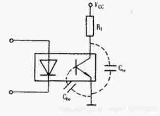
Due to the distributed capacitance of the optocoupler itself , Affect the transmission speed , There is a distributed capacitance inside the photosensitive triode Cbe and Cce, As shown in the figure . Because the current transmission of the optocoupler is relatively low , The collector load resistance should not be too small , Otherwise, the swing of the output voltage will be limited . however , The load resistance should not be too large , Load resistance RL The bigger it is , Due to the existence of distributed capacitance , The worse the frequency characteristic of the optocoupler , The longer the transmission delay .
Design of optocoupler power interface
In microcomputer measurement and control system , Power interface circuit is often used , In order to drive various types of loads , Such as DC servo motor 、 Stepper motor 、 Various solenoid valves . This kind of interface circuit generally has strong load carrying capacity 、 High output current 、 High working voltage .
The following figure is a typical circuit that uses optocouplers to isolate and drive DC loads . Because the current transmission ratio of ordinary optocoupler CRT A very small , Therefore, it is generally necessary to use a triode to amplify the output current , Darlington optocoupler can also be directly used to replace ordinary optocoupler T1.> For AC loads , Photoelectric thyristor driver can be used for isolation drive design , for example TLP541G,4N39. Photoelectric thyristor driver , It is characterized by high pressure resistance , The driving current is not large , When the AC load current is small , It can be directly used to drive .
When the load current is large , It can be externally connected with power bidirectional thyristor .
Buffer
Definition : Buffer is one of digital components , It does not perform any operation on the input value , The output value is the same as the input value , But it plays an important role in computer design .
classification : There are two types of buffers , Common buffers ( Conventional buffer ) And tristate buffer . Buffer can be divided into input buffer and output buffer .
frequently-used 74 series74HC34 Six buffers
74HC35 Six buffers (oc)
74HCO6 Six high voltage output inverted buffer / Driver (oc,30v)
74HC07 Six high voltage output buffers / Driver (oc,30v)
working principle
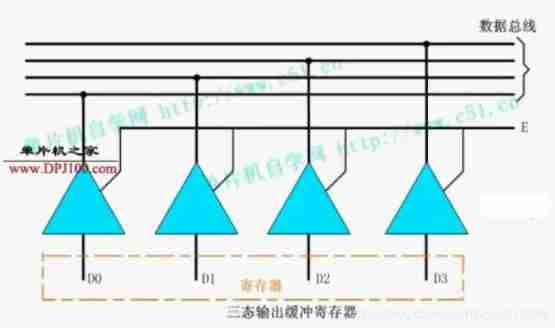
To reduce the number of information transmission lines , The information transmission lines in most computers are in the form of bus , That is to say, all the similar information to be transmitted will go through the same set of transmission lines , And the information is transmitted in time . There are generally three groups of buses in a computer , Data bus 、 Address bus and control bus . To prevent information from interfering with each other , It is required that any register or memory hung on the bus , Its transport side can not only present 0、1 Two message states , And it should also be able to present the third state - high impedance state ( Also known as high resistance state ), That is, at this time, it seems that their output is disconnected , No effect on bus status , At this time, the bus can be occupied by other devices . Three state gate can realize the above functions , It has input and output terminals , There is also a control end .
When control ends E=1 when , Output = Input , At this time, the bus is driven by the device , The data on the bus is determined by the input data ;
When control ends E=O when , The output is in high impedance state , The device doesn't work on the bus . When the register output terminal is connected to the tristate gate , The output terminal of the three state gate is connected with the bus , It constitutes the buffer register of three state output . As shown in the picture is a 4 Bit three state output buffer register . Because the one-way three state gate is used here , So data can only be output from register to data bus . If you want to achieve two-way transmission , Two way three state gate .
trigger
There are two kinds of bistable devices : One is trigger , One is latch . Latches are the original form of triggers .
trigger
Trigger has memory function , A basic logic unit that can store digital signals . The trigger has two steady states ,1 State and 0 state . Under the action of input trigger signal , The two stable states can be converted to each other , And it can keep the steady state of the signal after the trigger signal disappears .
Flip flops have monostable 、, Bistable and nonsteady triggers ( Multivibrator ) Several kinds .
.
Latch
Latch is a logic element with memory function in digital circuit . Latch , It is to store the signal temporarily to maintain a certain level state , Binary digital signals can be recorded in digital circuits “0” and “1”.
Only when there is a latch signal, the input state is saved to the output , Until the next latch signal . Usually only 0 and 1 Two values .
classification
Classified by structure : basic RS trigger 、 Sync RS Trigger 、 Master-slave RS trigger 、 Maintain blocking and edge triggers
By function :RS、JK、D、T and T` Type trigger
Divide according to the triggering method : Rising edge 、 Falling edge trigger and high level 、 Low level trigger
Counter
logic function
The basic function of the counter is to count the input clock pulses . It can also be used for frequency division 、 timing 、 Generate beat pulse and pulse sequence and carry out digital operation, etc .
classification
According to the pulse input mode , Divided into synchronous and asynchronous counters ;
According to the carry system , Divided into binary 、 Decimal and arbitrary base technology ; According to the logical function , It is divided into addition 、 Subtraction and reversible counters .
At the end of
Sorting is not easy to , If it helps you , Please like it , Collection , Focus on .
People are never immutable , Life will catch up with you again and again . As long as willing , You will always have a chance to be a person who keeps moving forward , Be the one you like !
边栏推荐
- Day7 list and dictionary jobs
- Iterator generators and modules
- 2022 ape circle recruitment project (software development)
- Appscan installation steps
- Locust learning record I
- Canoe: distinguish VT, VN and vteststudio from their development history
- 183 sets of free resume templates to help everyone find a good job
- Huge number (C language)
- On binary tree (C language)
- Function introduction of canbedded component
猜你喜欢
Canoe - the second simulation engineering - xvehicle - 2panel design (principle, idea)
Using SA token to solve websocket handshake authentication
Virtual machine configuration network
Function introduction of canbedded component
Canoe - the third simulation project - bus simulation-1 overview
Canoe - the third simulation project - bus simulation - 3-2 project implementation
Canoe - the third simulation project - bus simulation - 2 function introduction, network topology

Recursion and divide and conquer strategy
![[Galaxy Kirin V10] [desktop] cannot add printer](/img/a6/28e4aa31e805a018e6db2b32ca1be0.jpg)
[Galaxy Kirin V10] [desktop] cannot add printer
Postman interface test
随机推荐
[test theory] test process management
Performance test method
MFC document view framework (relationship between classes)
When I forget how to write SQL, I
Jemeter plug-in technology
For and while loops
Write a program to judge whether the elements contained in a vector < int> container are 9.20: exactly the same as those in a list < int> container.
[advantages and disadvantages of outsourcing software development in 2022]
Locust installation
JMeter correlation technology
MBG combat zero basis
The most ideal automated testing model, how to achieve layering of automated testing
Appscan installation error: unable to install from Net runtime security policy logout appscan solution
Using Lua to realize 99 multiplication table
[Galaxy Kirin V10] [desktop and server] FRP intranet penetration
Advanced order of function
Learning XML DOM -- a typical model for parsing XML documents
Iterator generators and modules
Dichotomy search (C language)
Canoe test: two ways to create CAPL test module
