当前位置:网站首页>Communication between different VLANs
Communication between different VLANs
2022-06-11 06:19:00 【chunxque】
Single arm routing
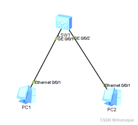
Topology

1. Switch configuration
1.1 establish vlan
establish vlan10 and 20:
[Huawei]vlan batch 10 201.2 Port configuration
take GE 0/0/1 Transfer in vlan10, GE 0/0/2 Transfer in vlan20, With GE 0/0/2 For example
GE 0/0/1
[Huawei]interfvace GigabitEthernet 0/0/1

[Huawei-GigabitEthernet0/0/1]port link-type access

[Huawei-GigabitEthernet0/0/1]port default vlan 10
GE 0/0/2
[Huawei]interfvace GigabitEthernet 0/0/2

[Huawei-GigabitEthernet0/0/2]port link-type access

[Huawei-GigabitEthernet0/0/2]port default vlan 20
see VLAN
display vlan

....

10 common UT:GE0/0/1(U) GE0/0/4(U)

20 common UT:GE0/0/2(U) GE0/0/5(U)
Put the port GE 0/0/3 Change the type to trunk, And allow vlan2 3 adopt :
[Huawei]interface GigabitEthernet 0/0/3

[Huawei-GigabitEthernet0/0/3]port link-type trunk

[Huawei-GigabitEthernet0/0/3]port trunk allow-pass vlan 10 20
see vlan
[Huawei]display vlan

.....

10 common UT:GE0/0/1(U) GE0/0/4(U) TG:GE0/0/3(U)

20 common UT:GE0/0/2(U) GE0/0/5(U) TG:GE0/0/3(U)
Exit and save the configuration , Pay attention to use save And select Y Press enter to save
2. Router configuration
Be careful : As shown in the figure above 0/0/0.1 For physics 0/0/0 The logical interface of , By configuring the logical interface , And this logic interface ip Address set to pc Gateway address for , At this point it can be guaranteed that vlan Communication between
0/0/0.1 To configure
[Huawei]interface Ethernet 0/0/0.1

[Huawei-Ethernet0/0/0.1]dot1q termination vid 10

[Huawei-Ethernet0/0/0.1]ip address 192.168.10.254 24
Turn on ARP radio broadcast
Description if the terminal sub interface is not configured arp broadcast enable, I can't take the initiative to send arp Broadcast message , The Second Committee will directly IP The message is discarded without forwarding .
[Huawei-Ethernet0/0/0.1]arp broadcast enableCheck the configuration
[Huawei-Ethernet0/0/0.1]

display this

# interface Ethernet0/0/0.1

dot1q termination vid 10

ip address 192.168.10.254 255.255.255.0
0/0/0.2 To configure
[Huawei]interface Ethernet 0/0/0.2

[Huawei-Ethernet0/0/0.2]dot1q termination vid 20

[Huawei-Ethernet0/0/0.2]ip address 192.168.20.254 24
Turn on ARP radio broadcast
[Huawei-Ethernet0/0/0.2]arp broadcast enableCheck the configuration
[Huawei-Ethernet0/0/0.2]display this

# interface Ethernet0/0/0.2

dot1q termination vid 20

ip address 192.168.20.254 255.255.255.0
dotlq termination vid 10 The meaning of this command : Because the router cannot handle the tape vlan The data frame of the tag , With this command, the data frame entering this interface can be removed vlan label , At the same time, the data frame sent from this interface will be marked with vlan10 label , Again dotlq termination vid 20 It's the same thing .
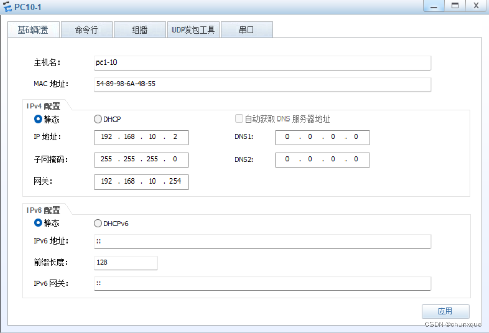
3.PC The network configuration
PC1 To configure
PC2 To configure

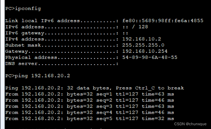
4. Experimental verification
stay PC1 On ping PC2
Router routing table
Three layer switch realizes VLAN Inter communication
GigabitEthernet 0/0/1 Configure to vlan10 A port vlanif 192.168.10.254/24
GigabitEthernet 0/0/2 Configure to vlan20 A port vlanif 192.168.20.254/24
- Switch configuration
Put... In the picture above PC1 Transfer in vlan10, take PC2 Transfer in vlan20
GigabitEthernet 0/0/1 Configure to vlan10 A port
[Huawei]interface GigabitEthernet 0/0/1

[Huawei-GigabitEthernet0/0/1]port link-type access

[Huawei]vlan 10 [Huawei-vlan10]port GigabitEthernet 0/0/1
GigabitEthernet 0/0/2 Configure to vlan20 A port
[Huawei]interface GigabitEthernet 0/0/2

[Huawei-GigabitEthernet0/0/2]port link-type access

[Huawei]vlan 20

[Huawei-vlan20]port GigabitEthernet 0/0/2
see vlan
[Huawei]display vlan
The total number of vlans is : 3
--------------------------------------------------------------------------------
...

10   common  UT:GE0/0/1(U)

20   common  UT:GE0/0/2(U)
To configure vlanif:
vlanif Introduce :
vlanif It is equivalent to changing the physical address of the switch to the logical address , To configure ip After the address, the layer 3 switch has the routing function , Every vlan Of vlanif amount to vlan Gateway for , Different at this time vlan Data can be forwarded in different network segments
vlan10 Interface configuration
[Huawei]interface Vlanif 10

[Huawei-Vlanif10]ip address 192.168.10.254 24
vlan20 Interface configuration
[Huawei]interface Vlanif 20

[Huawei-Vlanif20]ip address 192.168.20.254 24
Check the configuration ip
[Huawei-Vlanif20]display this

# interface Vlanif20

ip address 192.168.20.254 255.255.255.0
View routing table
[Huawei]display ip routing-tablePC1 To configure

PC2 To configure

2. experimental result

Make a difference VLAN Mutual access and access to the Internet
Purpose : Make a difference VLAN They can access each other and access the Internet
Three layer switch + Router + Broadband
Network topology

This experiment uses a PC Simulate as an external network host
PC host
Extranet PC host :192.168.2.2/24 gateway :192.168.2.1
PC1-V10:192.168.10.2/24 gateway :192.168.10.1
PC2-V20:192.168.20.2/24 gateway :192.168.20.1
R1 Router
Ethernet 0/0/0: 192.168.1.1/24
Ethernet 0/0/1: 192.168.1.2/24
Static routing
ip route-static 192.168.10.0 255.255.255.0 192.168.1.254
ip route-static 192.168.20.0 255.255.255.0 192.168.1.254
LSW3 Switch
GE 0/0/1 Vlan10 Vlanif:192.168.10.254/24
GE 0/0/2 Vlan20 Vlanif:192.168.20.254/24
GE 0/0/3 Vlan1 Vlanif:192.168.1.254/24
Static routing :
[Huawei]ip route-static 0.0.0.0 0.0.0.0 192.168.1.1
1. Switch configuration
1.1 establish vlan
establish vlan10 and 20:
[Huawei]vlan batch 10 201.2 Port configuration
take GE 0/0/1 Transfer in vlan10, GE 0/0/2 Transfer in vlan20, With GE 0/0/2 For example
GE 0/0/1
[Huawei]interfvace GigabitEthernet 0/0/1

[Huawei-GigabitEthernet0/0/1]port link-type access

[Huawei-GigabitEthernet0/0/1]port default vlan 10
GE 0/0/2
[Huawei]interfvace GigabitEthernet 0/0/2

[Huawei-GigabitEthernet0/0/2]port link-type access

[Huawei-GigabitEthernet0/0/2]port default vlan 20
see VLAN
display vlan
....
10   common  UT:GE0/0/1(U)      GE0/0/4(U)

20   common  UT:GE0/0/2(U)      GE0/0/5(U)
To configure vlanif1 Of ip by 192.168.1.254
[Huawei]interface Vlanif 1

[Huawei-Vlanif1]ip address 192.168.1.254 24
see vlanif ip
[Huawei-Vlanif1]display this
#
interface Vlanif1
 ip address 192.168.1.254 255.255.255.0
#
return
To configure vlanif10 Of ip by 192.168.10.254
[Huawei]interface Vlanif 10

[Huawei-Vlanif1]ip address 192.168.10.254 24
To configure vlanif20 Of ip by 192.168.20.254
[Huawei]interface Vlanif 20

[Huawei-Vlanif1]ip address 192.168.20.254 24
Static routing configuration
[Huawei]ip route-static 0.0.0.0 0.0.0.0 192.168.1.1View routing table
[Huawei]display ip routing-table
2. Router configuration
Be careful : As shown in the figure above 0/0/0.1 For physics 0/0/0 The logical interface of , By configuring the logical interface , And this logic interface ip Address set to pc Gateway address for , At this point it can be guaranteed that vlan Communication between
0/0/0 To configure
[Huawei]interface Ethernet 0/0/1

[Huawei-Ethernet0/0/1]ip address 192.168.1.1 24
Check the configuration
[Huawei-Ethernet0/0/0]display this
#
interface Ethernet0/0/1
 ip address 192.168.1.1 255.255.255.0
0/0/1 To configure
[Huawei]interface Ethernet 0/0/1

[Huawei-Ethernet0/0/1]ip address 192.168.2.1 24
Check the configuration
[Huawei-Ethernet0/0/1]display this
#
interface Ethernet0/0/1
 ip address 192.168.2.1 255.255.255.0
Static routing configuration
ip route-static 192.168.10.0 255.255.255.0 192.168.1.254

ip route-static 192.168.20.0 255.255.255.0 192.168.1.254
Save configuration
3.PC The network configuration
PC1 To configure
PC2 To configure
4. verification
PC1 visit PC2
PC1 Access the Internet host

PC2 Visit the Internet

Extranet access PC1

边栏推荐
- Use of constructors
- FPGA interview notes (II) -- synchronous asynchronous D flip-flop, static and dynamic timing analysis, frequency division design, retiming
- Chapter 2 of machine learning [series] logistic regression model
- Which company is better in JIRA organizational structure management?
- FPGA面试题目笔记(一)——FPGA开发流程、亚稳态和竞争冒险、建立保持时间、异步FIFO深度等
- Simple knapsack problem
- Goodbye 2021 Hello 2022
- Sign for this "plug-in" before returning home for the new year
- [usual practice] explore the insertion position
- go的fmt包使用和字符串的格式化
猜你喜欢

Review Servlet

ERROR 1215 (HY000): Cannot add foreign key constraint

Sqli-labs less-01

FPGA面试题目笔记(一)——FPGA开发流程、亚稳态和竞争冒险、建立保持时间、异步FIFO深度等

Matlab实现均值滤波与FPGA进行对比,并采用modelsim波形仿真

Convert multiple pictures into one NPY file storage
![[IOS development interview] operating system learning notes](/img/1d/2ec6857c833de00923d791f3a34f53.jpg)
[IOS development interview] operating system learning notes

Sqoop installation tutorial

Yonghong Bi product experience (I) data source module
![Experimental report on information management and information system [information security and confidentiality] of Huazhong Agricultural University](/img/f6/e58196aeac85178f6603cea1962a6e.jpg)
Experimental report on information management and information system [information security and confidentiality] of Huazhong Agricultural University
随机推荐
jenkins-凭证管理
Review XML and JSON
Yonghong Bi product experience (I) data source module
Use of constructors
Jenkins voucher management
Sqli-labs less-01
Record the first data preprocessing process
This point of arrow function
FPGA interview notes (IV) -- sequence detector, gray code in cross clock domain, ping-pong operation, static and dynamic loss reduction, fixed-point lossless error, recovery time and removal time
[usual practice] explore the insertion position
亚马逊、速卖通、Lazada、虾皮平台在用911+VM的环境可以进行产号、养号、补单等操作吗?
Which company is better in JIRA organizational structure management?
Using idea to add, delete, modify and query database
Wechat applet (authorized login) (not recommended, click the home page to view the updated authorized login)
Twitter data collection (content, fans, keywords, etc.)
What should the cross-border e-commerce evaluation team do?
This is probably the most comprehensive project about Twitter information crawler search on the Chinese Internet
Chapter 2 of machine learning [series] logistic regression model
Shandong University machine learning experiment 7 pca+ SVM face recognition
Stock K-line drawing