当前位置:网站首页>Getting started stm32--gpio (running lantern) (nanny level)
Getting started stm32--gpio (running lantern) (nanny level)
2022-07-05 22:55:00 【CSJ_ HYL】
Catalog
3、 ... and 、 How to use GPIO Light up a LED The lamp
Preface
This is also a relatively simple part , Let's officially start our 32 The way .
These are the basics , If you want to understand the program , Understanding can .
One 、GPIO What is it? ?
All embedded processors have integrated general input and output (General Purpose Input Output,GPIO) Interface , Generally speaking , In fact, it is the pin on your development version , That thing is on your SCM IO mouth (GPIO) It's connected ( It's easy to connect , Easy to develop ). STM32 Of IO The mouth is divided into several groups ,PA、PB、PC etc. , Each group has 16 A pin ,PA0、PA1、PA2、PA3 wait .
Two 、GPIO What for?
from Output Input These two words can also be seen , He does input and output .
Our single-chip microcomputer is generally the main control , To control other circuits or motors , Since it is control, it must output control signals , So we need IO mouth , To do the output . Again , SCM certainly also needs external information , So input function is also required .
The most basic output function is made up of STM32 Control pin output high 、 Low level , Switch control is realized , If you put GPIO Pin into LED The lamp , Then you can control LED The light goes on and off , Pin into relay or triode , Then you can control the on-off of external high-power circuits through relays or triodes .
3、 ... and 、GPIO How to do it
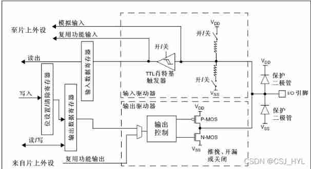
To put it simply , This diagram can be divided into two parts , It's the input , Here is the output .
Look from right to left , First the pin, then the protective diode ( The function is to protect your pin from being compared 3V3 It could be 5V Higher , Or 0V Lower voltage damage , But remember one thing ), Let's move on to two parts .
The input part is , After entering, pull up or pull down the resistance , And then there was TTL Schottky trigger (TTL Schottky trigger can be understood as Schmidt trigger composed of Schottky tube , The function is simply to turn the relatively slow changing analog signal into a rectangular signal , Easy to read later .) Then it can be read .
Output part , Is a MOS The conduction and disconnection of the tube control the output level . You can see , When the highest level is output VDD( Working voltage of single chip microcomputer ,2.0~3.6V, It's usually 3.3V), The lowest level is Vss( SCM power supply ground ,0V).
3、 ... and 、 How to use GPIO Light up a LED The lamp
without doubt , We definitely need to write code , Through the code we wrote , Tell SCM what we want to do .
If the function we choose is input , Then what we need is to read the relevant registers ( It can be understood as a memory , We can write numbers inside , You can control SCM . Again , Some data of the single chip microcomputer is also stored here .) Value , You can get relevant IO The level of the port , If we choose output , What we need to do is control MOS Turn on and off the tube .
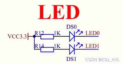
The first thing we need to do is determine what we want to use IO mouth , We should look for the schematic , And then find LED The pin corresponding to the lamp .
![]()
We can see ,LED0 The corresponding is PB5 This pin , The next thing to do is to write a program .
1. GPIO_InitTypeDef
First , We're going to define a structure , It's mentioned above , We control the SCM by writing numbers into the register , Registers are converted into programs and divided into many structures , We need to write numbers in it , Also through the way of structure .
GPIO_InitTypeDef GPIO_InitStructure;This GPIO_InitTypeDef It's through typedef Get a macro definition , It is convenient to use it to define variables and GPIO The register type structure conforms to the structure . The one in the back GPIO_InitStructure Is the structure we define ( Random names , This is what I call it when I study ).
typedef struct
{
  uint16_t GPIO_Pin;             /*!< Specifies the GPIO pins to be configured.
                                      This parameter can be any value of @ref GPIO_pins_define */

  GPIOSpeed_TypeDef GPIO_Speed;  /*!< Specifies the speed for the selected pins.
                                      This parameter can be a value of @ref GPIOSpeed_TypeDef */

  GPIOMode_TypeDef GPIO_Mode;    /*!< Specifies the operating mode for the selected pins.
                                      This parameter can be a value of @ref GPIOMode_TypeDef */
}GPIO_InitTypeDef;
Now let's analyze the members in this structure ,
1. GPIO_Pin It means Which pin , for example GPIO_Pin_5, It stands for PX5 This pin , among X=A、B、C、D etc. .
GPIO_InitStructure.GPIO_Pin = GPIO_Pin_5;
2.GPIOSpeed_TypeDef GPIO_Speed, Here is an enumeration definition , The preceding is the type of enumeration , Followed by the name of the enumeration .
GPIO Pin speed : GPIO_Speed_2MHz (10MHz, 50MHz) ;
Also known as the response speed of the output drive circuit :( Inside the chip is I/O The output part of the port is arranged with a number of output driving circuits with different response speed , Users can choose the right driving circuit according to their own needs , Select different output driver modules by selecting speed , Achieve the best noise control and reduce power consumption .)
The simple understanding is ,IO Response speed of mouth .
GPIO_InitStructure.GPIO_Speed = GPIO_Speed_50MHz;
typedef enum
{
  GPIO_Speed_10MHz = 1,
  GPIO_Speed_2MHz,
  GPIO_Speed_50MHz
}GPIOSpeed_TypeDef;3.GPIOMode_TypeDef GPIO_Mode Obvious , Here is another definition of enumeration , The front is the type , Followed by the name .
typedef enum
{ GPIO_Mode_AIN = 0x0,
  GPIO_Mode_IN_FLOATING = 0x04,
  GPIO_Mode_IPD = 0x28,
  GPIO_Mode_IPU = 0x48,
  GPIO_Mode_Out_OD = 0x14,
  GPIO_Mode_Out_PP = 0x10,
  GPIO_Mode_AF_OD = 0x1C,
  GPIO_Mode_AF_PP = 0x18
}GPIOMode_TypeDef;
There are different modes , If we choose output ,GPIO_Mode_Out_PP That's what we want , It is called push-pull output , There are many other ways , I won't go into details , You can refer to other articles .
GPIO_InitStructure.GPIO_Mode = GPIO_Mode_Out_PP;
2.GPIO_Init
After we configure the above structure members , We have finished most of , But it's not over , You'll find that , We just determine the value in the structure of our definition , It is not put into the register of the single chip microcomputer , Certainly not at this time .
How to put it in , Others thought of this in , Call the function directly .

GPIO_Init(GPIOB, &GPIO_InitStructure);
You can see , This function needs to input two parameters , One is A、B、C、D etc. , Determine which set of pins we want to control .
Another parameter is the address of the structure we define .
For example , The structure we define is better than a package , This function is the courier , What we want to tell you is which express we send , To where .
You may feel almost here , In fact, there is no . Are we going to tell the person who receives the express , You have express delivery , How to tell , A function is OK 了 .
3.RCC_APB2PeriphClockCmd
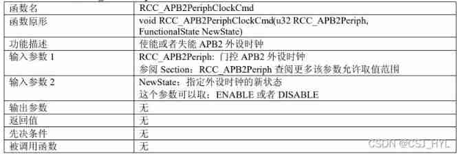
RCC_APB2PeriphClockCmd(RCC_APB2Periph_GPIOB, ENABLE);
You can see , This function also has two arguments , The first parameter is the clock of which group of pins is enabled , The second pin is enable (ENABLE).
The reason why the peripheral clock is enabled  https://blog.csdn.net/weixin_43217963/article/details/97792677 Be careful : Be sure to enable PB The clock of the port is then configured GPIO
void GPIO_Init(void)
{
GPIO_InitTypeDef GPIO_InitStructure;
RCC_APB2PeriphClockCmd(RCC_APB2Periph_GPIOB, ENABLE); // Can make PB Port clock
GPIO_InitStructure.GPIO_Pin = GPIO_Pin_5; //PB.5 port configuration
GPIO_InitStructure.GPIO_Mode = GPIO_Mode_Out_PP; // Push pull output
GPIO_InitStructure.GPIO_Speed = GPIO_Speed_50MHz; //IO The mouth speed is 50MHz
GPIO_Init(GPIOB, &GPIO_InitStructure); // Initialize according to the set parameters GPIOB.5
GPIO_SetBits(GPIOB,GPIO_Pin_5); //PB.5 High output
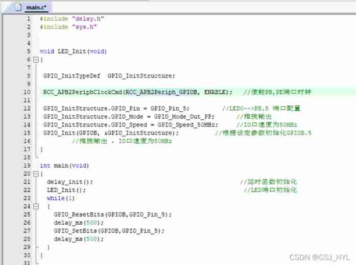
}Four 、 initialization
Initialization is an important problem , Many novices have written the function after experiencing all kinds of difficulties and dangers , Get the program in , I found the light doesn't work .BBQ 了 , Most of the reasons are initialization .
Maybe many novices have created a new file LED, There are led.c and led.h These two documents , Put the function written by yourself into led.c Inside the , It's ok , But there is no need , I still suggest writing directly main.c In this document , After all, we're just lighting a light .
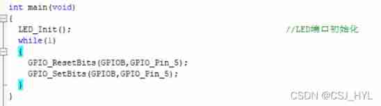
Just like this
Although not written led.c It's simple inside , But initialization will be much more convenient ( Avoid many pits ).
If you have to create a file , Be sure to remember in led.h It says ,main.c The file should include relevant header files .
5、 ... and 、 synthesis
Put together what we wrote before , Like this
But you will find , The light is always on , This is because the execution speed of MCU is very fast , The setting of high and low levels is completed in an instant , Human eyes can't react .
So you need a delay function , Just let the light come on later , Also wait for a while .
Time delay
There are two ways to delay , The first is that we can call the delay function directly ( Functions written by others ), You can also write a cycle to delay .
Let's just use the first one , All you need to do is include the corresponding header file , And initialization delay function .
The header file
Just include it directly in the main function
![]()
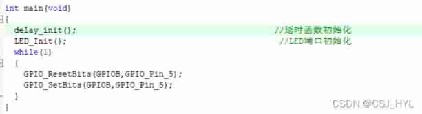
initialization
add a sentence delay_init(); that will do
delay_ms(200); It's a delay 200 millisecond
delay_ms(500); It's a delay 500 millisecond
Be careful : The single delay time cannot exceed 1864ms
Add the delay function
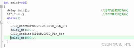
The light flashed ~~~
6、 ... and 、 Two lights
Just like this.
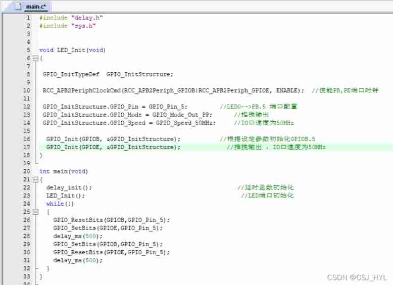
Give a brief explanation , First, there is one more port clock PE Of , You can use a function directly , But notice one or Steps for .
The second place is , In the configuration PE5 when , The last structure is still used . Because the second lamp is also pin 5 , No other changes are required .
The third place is the main function , It's easy here, too , Just two more sentences .
边栏推荐
- Binary tree (III) -- heap sort optimization, top k problem
- Global and Chinese market of diesel fire pump 2022-2028: Research Report on technology, participants, trends, market size and share
- Thoroughly understand JVM class loading subsystem
- QT creator 7-cmake update
- Arduino measures AC current
- 利用LNMP实现wordpress站点搭建
- [speech processing] speech signal denoising and denoising based on Matlab GUI low-pass filter [including Matlab source code 1708]
- Evolution of APK reinforcement technology, APK reinforcement technology and shortcomings
- Ultrasonic sensor flash | LEGO eV3 Teaching
- Leetcode weekly The 280 game of the week is still difficult for the special game of the week's beauty team ~ simple simulation + hash parity count + sorting simulation traversal
猜你喜欢
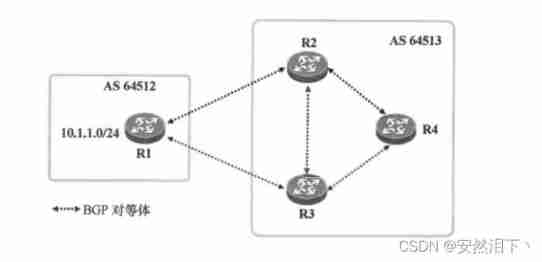
Hcip day 12 (BGP black hole, anti ring, configuration)
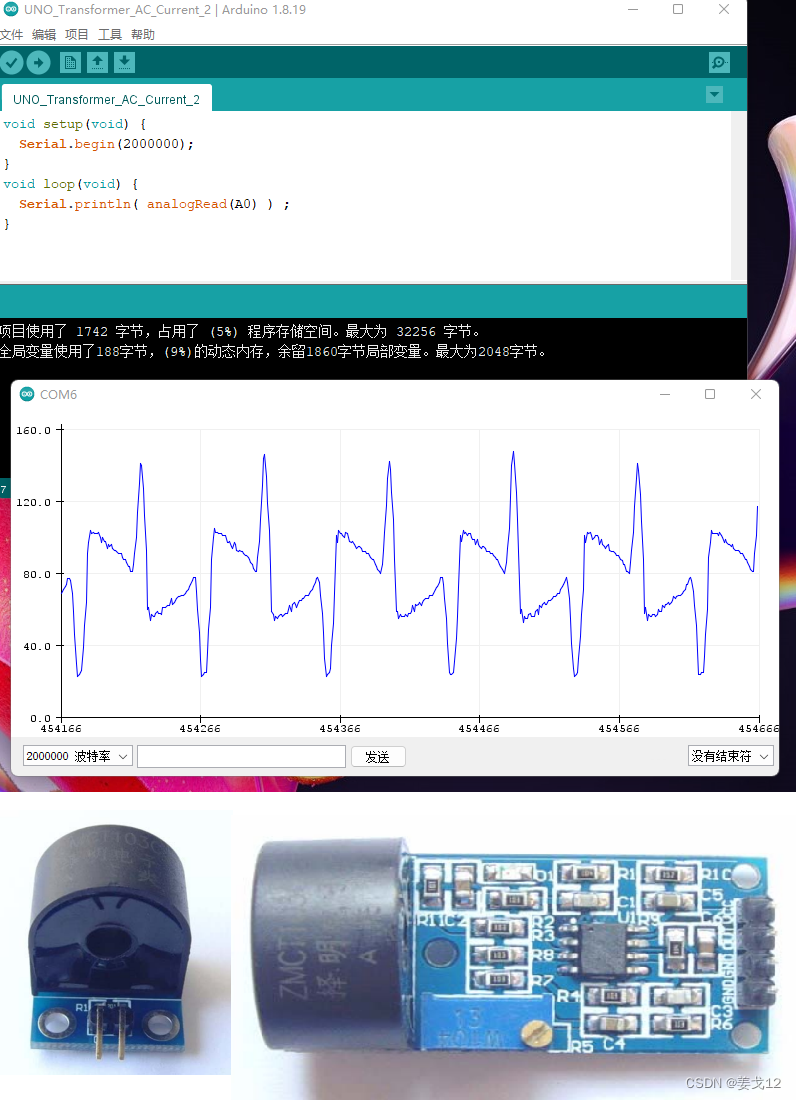
Arduino 测量交流电流
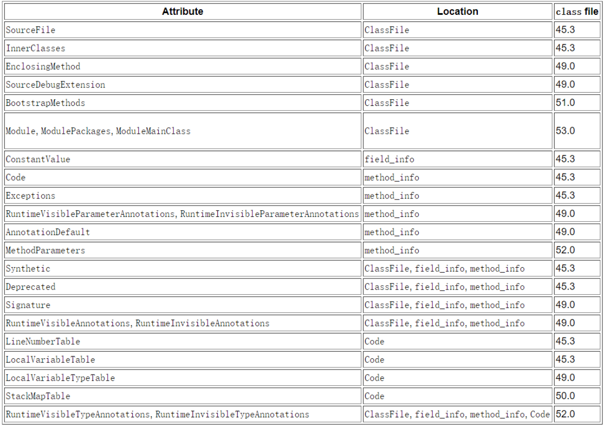
一文搞定class的微观结构和指令
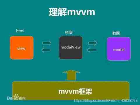
The difference between MVVM and MVC
The method and principle of viewing the last modification time of the web page
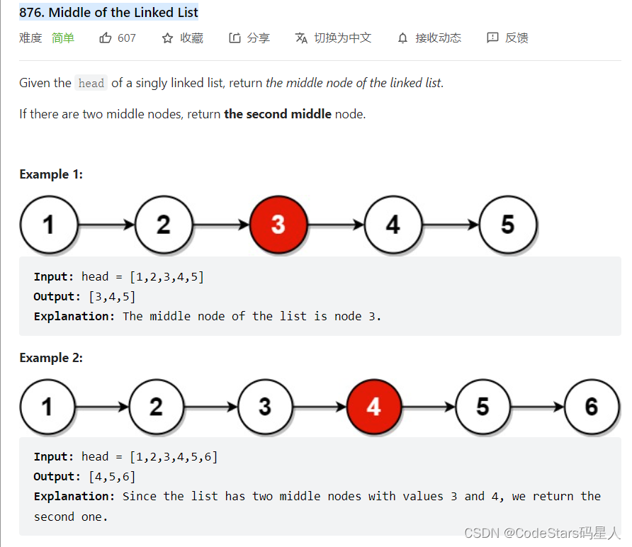
鏈錶之雙指針(快慢指針,先後指針,首尾指針)

Matlab smooth curve connection scatter diagram
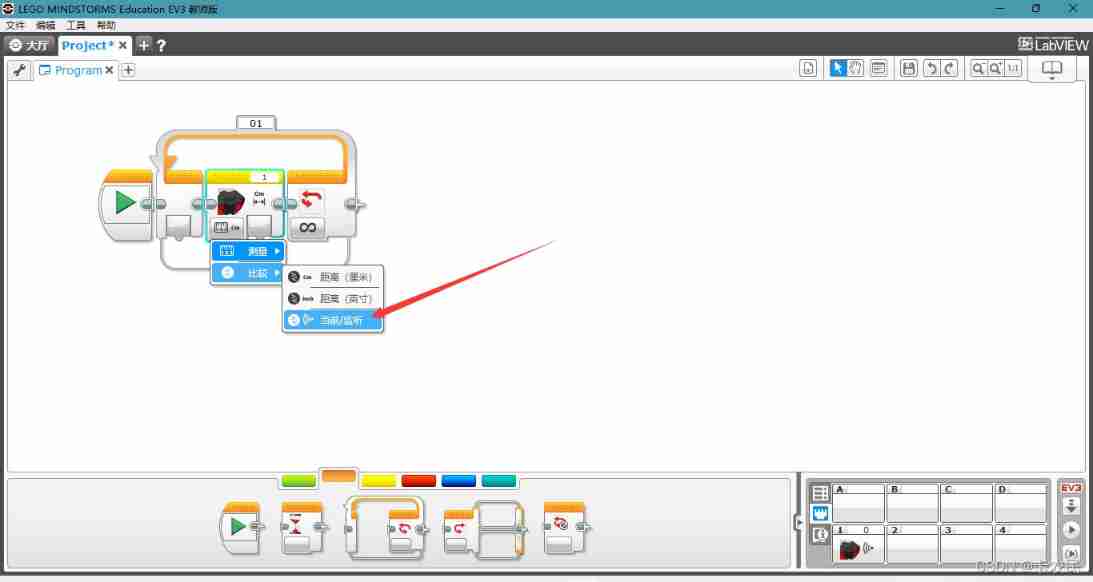
Ultrasonic sensor flash | LEGO eV3 Teaching
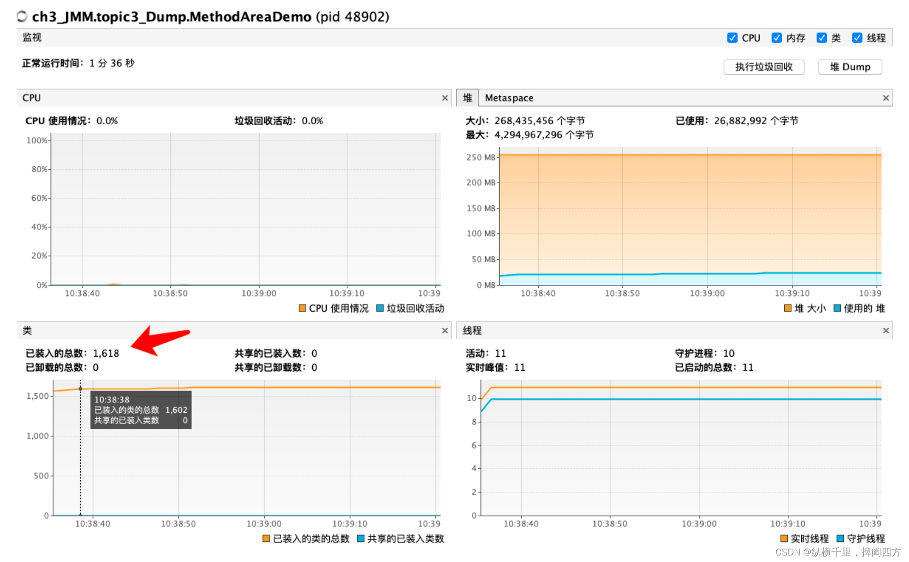
一文搞定JVM的内存结构
點到直線的距離直線的交點及夾角
随机推荐
Vision Transformer (ViT)
TOPSIS code part of good and bad solution distance method
Finally understand what dynamic planning is
Global and Chinese markets of industrial pH meters 2022-2028: Research Report on technology, participants, trends, market size and share
Tiktok__ ac_ signature
VIM tail head intercept file import
Composition of interface
Paddy serving v0.9.0 heavy release multi machine multi card distributed reasoning framework
Postman core function analysis - parameterization and test report
Usage Summary of scriptable object in unity
Error when LabVIEW opens Ni instance finder
How to create a thread
[untitled]
Arduino 测量交流电流
请求二进制数据和base64格式数据的预览显示
Business introduction of Zhengda international futures company
Google Maps case
Simple and beautiful method of PPT color matching
Request preview display of binary data and Base64 format data
The countdown to the launch of metaverse ape is hot