当前位置:网站首页>ESP Arduino (IV) PWM waveform control output
ESP Arduino (IV) PWM waveform control output
2022-07-07 01:02:00 【pocean2012】
PWM As an important IO Output function , Widely applied , Common applications include :
1. Motor control ( adjust speed , Torque adjustment , Constant voltage / constant current / Constant torque control and so on )
2. Control the buzzer output tone
3. Play the sound file
4. Breathing lights
In a simple and crude way , It can be simulated directly with software
/*
gen the PMW pulse via software
*/

#define PULSE 18
#define LED 22
// the setup function runs once when you press reset or power the board
void setup() {
  // initialize digital pin LED_BUILTIN as an output.
  pinMode(PULSE, OUTPUT);
  Serial.begin(115200);
}
int loop_count=0;
// the loop function runs over and over again forever
void loop() {

  digitalWrite(PULSE, HIGH);   // turn the LED on (HIGH is the voltage level)
  delayMicroseconds(20);                       // wait for a second
  digitalWrite(PULSE, LOW);    // turn the LED off by making the voltage LOW
  delayMicroseconds(10);                       // wait for a second


}
Can be controlled LED The brightness of , If you use Logic Grab waveform , Like this :
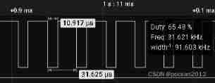
Low level 10us, The whole cycle 30us( Of course , It's about the same , Generally, add the time of software code execution ,us level ), It is basically consistent with the program setting .
But such examples are not practical , because CPU It's all occupied , Nothing else can be done .
So we need to have a way of background execution , Can be combined with other applications .
ESP32 stay arduino There is no PWM routine , Didn't like Arduino Official boards and so on analogWrite Method , So you can use it LEDC Control interface to output PWM wave , For the convenience of study , It can cooperate with logic analyzer software to capture and analyze waveforms .
Download link on official website :
Logic analyzer software from Saleae
Plug in can be customized , You can also use python To call API, Very powerful ! The page is also much more beautiful than the old version .
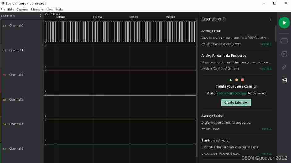
ESP32 Of LEDC Interface is used to generate PWM Very convenient , See the article below
ESP32 Learning notes (15)——LEDC(PWM) Interface to use - Simple books
LEDC Interface function method
ESP32 There is one LEDC, Originally designed to control LED, You can do simple PWM Output , You can specify output to any GPIO.
LEDC All in all 16 Three way passage (0 ~ 15), Divided into high and low speed groups , High speed channel (0 ~ 7) from 80MHz Clock driven , Low speed channel (8 ~ 15) from 1MHz Clock driven .
Method function :
double ledcSetup(uint8_t channel, double freq, uint8_t resolution_bits)
channel Is the channel number , Value 0 ~ 15;
freq, Set the frequency ;
resolution_bits Count digits , Value 0 ~ 20( This value determines the following ledcWrite The maximum value of the duty cycle in the method , If this value is written 10, Then the maximum duty cycle can be written 2^10-1=1023 ;
Channel final frequency = clock frequency / ( Division coefficient * ( 2^ Count digits ) );( The maximum division coefficient is 1024)
Case a , Output PWM square wave
#include <Arduino.h>

int freq = 2000;    //  frequency
int channel = 0;    //  passageway
int resolution = 8;   //  The resolution of the
int dutyCycle=100;    //

const int led = 18; // define the pin

void setup()
{

  ledcSetup(channel, freq, resolution); //  Set up channels
  ledcAttachPin(led, channel);  //  Connect the channel to the corresponding pin

  ledcWrite(channel, dutyCycle);  //  Output PWM
}

void loop()
{

}
Output waveform
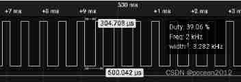
From the measured data, we can see the frequency 2K, The duty cycle is close to 40%(100/255 Also almost )
Case 2 . Changing PWM wave -- Breathing lights
#include <Arduino.h>

int freq = 1000;    //  frequency
int channel = 0;    //  passageway
int resolution = 8;   //  The resolution of the

const int led = 18;
void setup()
{

  ledcSetup(channel, freq, resolution); //  Set up channels
  ledcAttachPin(led, channel);  //  Connect the channel to the corresponding pin
}

void loop()
{
  //  Gradually brighten
  for (int dutyCycle = 0; dutyCycle <= 255; dutyCycle = dutyCycle + 5)
  {
    ledcWrite(channel, dutyCycle);  //  Output PWM
    delay(20);
  }

  //  Gradually darken
  for (int dutyCycle = 255; dutyCycle >= 0; dutyCycle = dutyCycle - 5)
  {
    ledcWrite(channel, dutyCycle);  //  Output PWM
    delay(20);
  }
}
Observe the effect of breathing lamp
Case three . Play sounds of different tones , It must be matched with a buzzer with drive or a horn with power amplifier , Unfortunately, there is no
边栏推荐
- C9 colleges and universities, doctoral students make a statement of nature!
- Build your own website (17)
- Return to blowing marshland -- travel notes of zhailidong, founder of duanzhitang
- Stm32f407 ------- SPI communication
- ZABBIX 5.0: automatically monitor Alibaba cloud RDS through LLD
- mongodb客户端操作(MongoRepository)
- There is an error in the paddehub application
- 在jupyter中实现实时协同是一种什么体验
- paddlehub应用出现paddle包报错的问题
- Part IV: STM32 interrupt control programming
猜你喜欢

C9高校,博士生一作发Nature!
「精致店主理人」青年创业孵化营·首期顺德场圆满结束!
![Explain in detail the matrix normalization function normalize() of OpenCV [norm or value range of the scoped matrix (normalization)], and attach norm_ Example code in the case of minmax](/img/87/3fee9e6f687b0c3efe7208a25f07f1.png)
Explain in detail the matrix normalization function normalize() of OpenCV [norm or value range of the scoped matrix (normalization)], and attach norm_ Example code in the case of minmax
Distributed cache
学习光线跟踪一样的自3D表征Ego3RT
【JVM调优实战100例】05——方法区调优实战(下)
Activereportsjs 3.1 Chinese version | | | activereportsjs 3.1 English version
Set (generic & list & Set & custom sort)
城联优品入股浩柏国际进军国际资本市场,已完成第一步

Windows installation mysql8 (5 minutes)
随机推荐
fastDFS数据迁移操作记录
学习光线跟踪一样的自3D表征Ego3RT
Anfulai embedded weekly report no. 272: 2022.06.27--2022.07.03
Zabbix 5.0:通过LLD方式自动化监控阿里云RDS
Explain in detail the matrix normalization function normalize() of OpenCV [norm or value range of the scoped matrix (normalization)], and attach norm_ Example code in the case of minmax
「精致店主理人」青年创业孵化营·首期顺德场圆满结束!
Dell筆記本周期性閃屏故障
Building a dream in the digital era, the Xi'an station of the city chain science and Technology Strategy Summit ended smoothly
Advanced learning of MySQL -- basics -- multi table query -- subquery
from .cv2 import * ImportError: libGL.so.1: cannot open shared object file: No such file or direc
ActiveReportsJS 3.1中文版|||ActiveReportsJS 3.1英文版
Cause of handler memory leak
新手如何入门学习PostgreSQL?
build. How to configure the dependent version number in the gradle file
Slow database query optimization
第七篇,STM32串口通信编程
pyflink的安装和测试
Installation and testing of pyflink
.class文件的字节码结构
Return to blowing marshland -- travel notes of zhailidong, founder of duanzhitang