当前位置:网站首页>Questions and answers of "basic experiment" in the first semester of the 22nd academic year of Xi'an University of Electronic Science and technology
Questions and answers of "basic experiment" in the first semester of the 22nd academic year of Xi'an University of Electronic Science and technology
2022-07-06 13:20:00 【fantiantianL】
Answer private chat ...


边栏推荐
- MySQL Database Constraints
- 167. Sum of two numbers II - input ordered array - Double pointers
- arduino+DS18B20温度传感器(蜂鸣器报警)+LCD1602显示(IIC驱动)
- 阿里云微服务(一)服务注册中心Nacos以及REST Template和Feign Client
- 13 power map
- Error: sorting and subscript out of bounds
- TYUT太原理工大学2022“mao gai”必背
- 十分鐘徹底掌握緩存擊穿、緩存穿透、緩存雪崩
- Inheritance and polymorphism (I)
- Arduino+ water level sensor +led display + buzzer alarm
猜你喜欢

Differences and application scenarios between MySQL index clock B-tree, b+tree and hash indexes
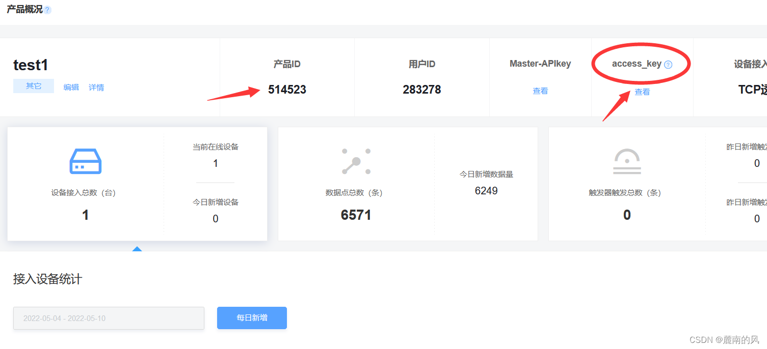
(超详细二)onenet数据可视化详解,如何用截取数据流绘图
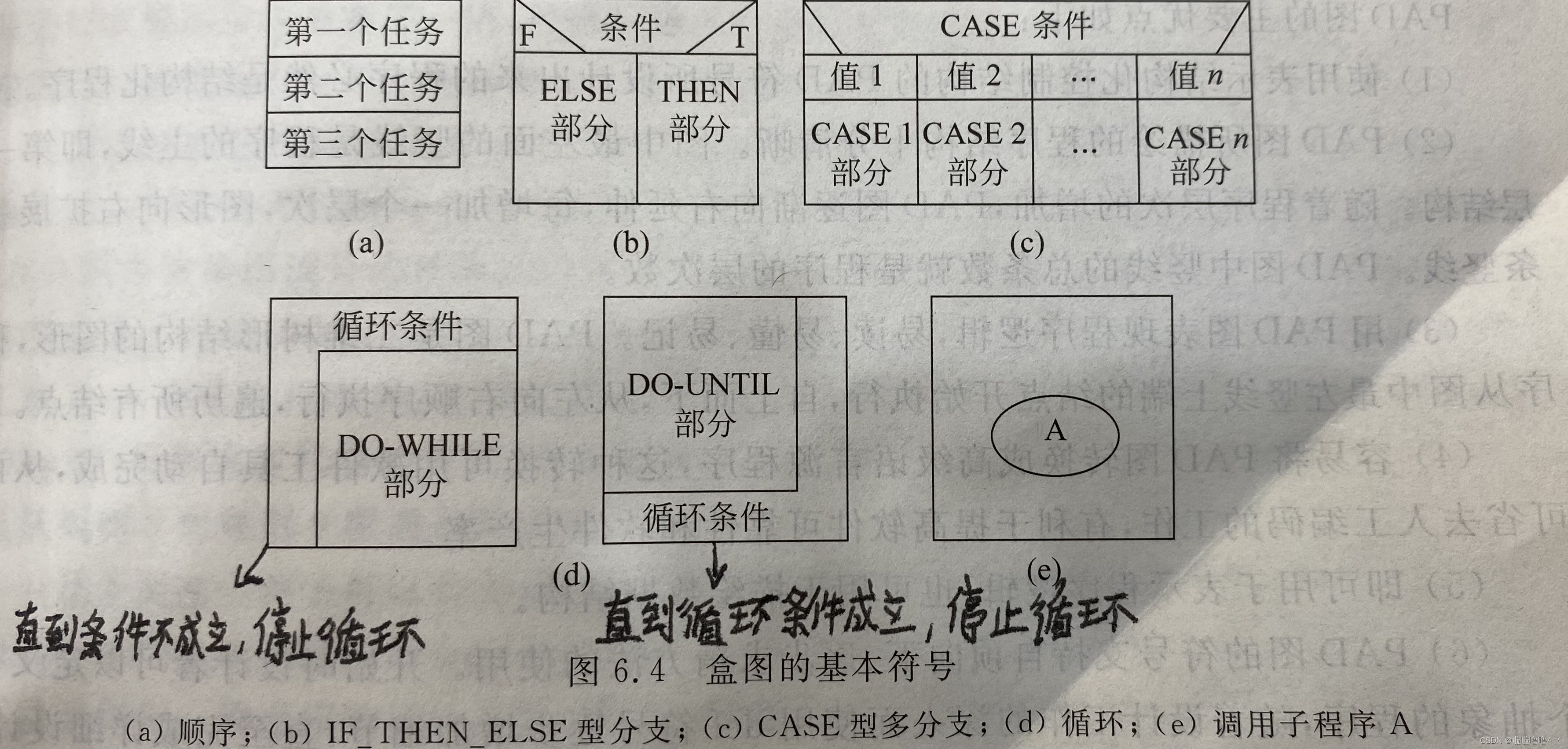
TYUT太原理工大学2022软工导论大题汇总

2-year experience summary, tell you how to do a good job in project management
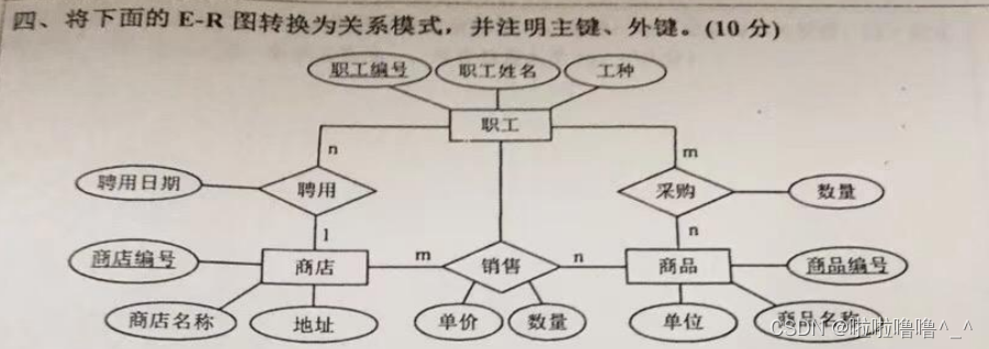
E-R graph to relational model of the 2022 database of tyut Taiyuan University of Technology
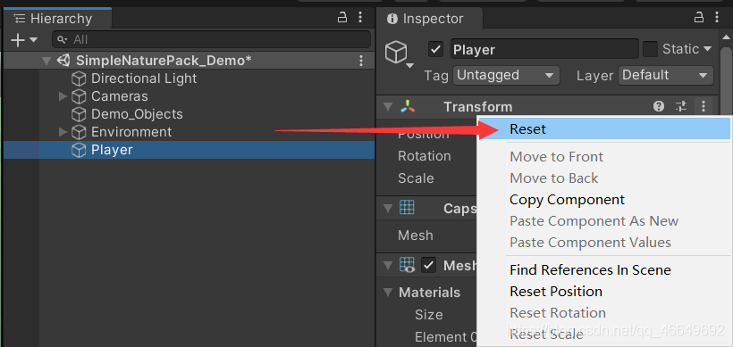
Role movement in the first person perspective

TYUT太原理工大学2022数据库大题之E-R图转关系模式
架构师怎样绘制系统架构蓝图?

View UI Plus 发布 1.3.0 版本,新增 Space、$ImagePreview 组件
Redis介绍与使用
随机推荐
【快趁你舍友打游戏,来看道题吧】
如何保障 MySQL 和 Redis 的数据一致性?
TYUT太原理工大学2022软工导论大题汇总
TYUT太原理工大学2022数据库大题之E-R图转关系模式
CorelDRAW plug-in -- GMS plug-in development -- Introduction to VBA -- GMS plug-in installation -- Security -- macro Manager -- CDR plug-in (I)
十分鐘徹底掌握緩存擊穿、緩存穿透、緩存雪崩
初识指针笔记
系统设计学习(二)Design a key-value cache to save the results of the most recent web server queries
阿里云微服务(四) Service Mesh综述以及实例Istio
Dark chain lock (lca+ difference on tree)
六种集合的遍历方式总结(List Set Map Queue Deque Stack)
The overseas sales of Xiaomi mobile phones are nearly 140million, which may explain why Xiaomi ov doesn't need Hongmeng
Employment of cashier [differential constraint]
Application architecture of large live broadcast platform
一文搞定 UDP 和 TCP 高频面试题!
RTKLIB: demo5 b34f. 1 vs b33
分支语句和循环语句
What are the advantages of using SQL in Excel VBA
TYUT太原理工大学2022数据库大题之分解关系模式
System design learning (I) design pastebin com (or Bit.ly)