当前位置:网站首页>FOC control
FOC control
2022-07-04 08:22:00 【A record of juechen】
FOC Control basics
0. Preface
0.1 What is? FOC
FOC(Field-Oriented Control), Magnetic field oriented control , Also known as vector control (VC,Vector Control), Is the current brushless DC motor (BLDC) And permanent magnet synchronous motor (PMSM) One of the best methods of efficient control .FOC It aims at precisely controlling the magnitude and direction of the magnetic field , Make the motor movement torque stable 、 Small noise 、 Efficient , And it has high-speed dynamic response .
0.2 FOC The difference between driver and brushless electric regulator
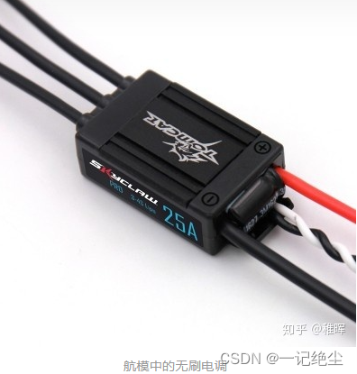
FOC The advantages of :
- Control at low speed
Due to the difference of control principle , Brushless electric regulator can only control the motor to work at high speed , It is difficult to control at low speed ; and FOC The controller has no such limitation at all , Precise control can be achieved at any speed . - Motor commutation
The same reason as above , Due to non inductive regulation, the rotor position cannot be fed back , Therefore, it is difficult to realize the forward and reverse commutation of the motor ; and FOC The commutation performance of the driver is extremely excellent , The forward and reverse switching can be very smooth at the highest speed ; Besides FOC Braking control can also be carried out in the form of energy recovery . - Torque control
Ordinary electric regulators can only control the motor speed , and FOC It can carry out current ( Moment )、 Speed 、 The position is controlled by three closed loops . - The noise
FOC The noise of the driver will be much lower than that of the electric regulator , The reason is that the ordinary electric regulator adopts square wave drive , and FOC It's a sine wave .
Advantages of electric regulation :
- Compatibility
Electrically adjustable drive different BLDC No parameter setting is required , and FOC need . - Algorithm complexity
The algorithm of electric regulation is simpler , Less computation , It is very suitable for ultra-high speed motors that need to improve bandwidth . - cost
The cost ratio of electric regulation FOC A lot lower .
Starting from the principle of motor
1.1 Some basics
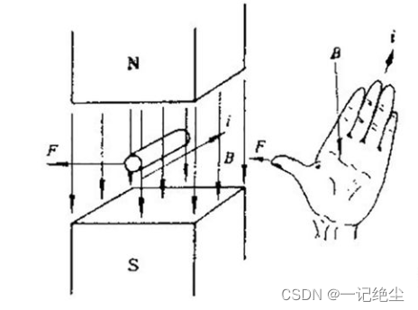
- Left hand rule
It is used to judge the direction of force on the wire in the magnetic field : Stretch out your left hand , Make the thumb perpendicular to the other four fingers and in a plane , Let the magnetic line flow from the palm of your hand , The four fingers point in the direction of the current , The thumb points in the direction of Ampere force ( That is, the stress direction of the conductor ).
- Right-hand rule
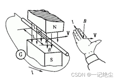
Stretch out your right hand , Make the thumb perpendicular to the other four fingers and in the same plane with the palm , Put your right hand into the magnetic field , Let the magnetic induction line penetrate into the palm vertically , Thumb points to the direction of conductor movement , Then the other four fingers point to the direction of the induced electromotive force . That is, the conductor cutting the magnetic induction line will produce back EMF , In fact, locating the rotor position by back EMF is also one of the basic principles of ordinary non inductive regulation
- Right hand spiral rule ( The ampere rule )
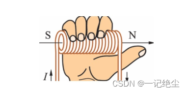
Used to judge the polarity of the energized coil : Hold the solenoid with your right hand , Bend the four fingers in the direction of the current in the solenoid , The end pointed by the thumb is the end of the solenoid N extremely . Magnetic field of linear current , Thumb points to the direction of current , The other four fingers bend in the direction of the magnetic induction line .
- PWM( Pulse width modulation )
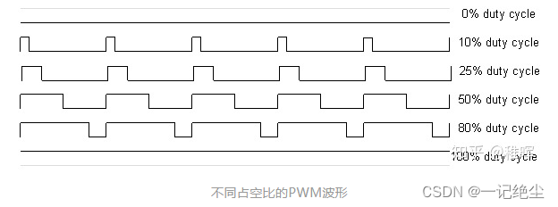
The essence is to use the principle of area equivalence to change the effective value of the waveform . for instance , An electric light has only open and Turn off Two states , So how to make it happen 50% brightness The effect of ? Just let it in half the time open , Half the time Turn off , Perform these two actions alternately as long as the frequency is high enough , In human eyes ( low pass filter ) It looks like 50% brightness What it looks like . And the proportion of high level in a switching cycle , It's called Duty cycle . utilize PWM It is possible to use discrete switching values to simulate continuous voltage values .
1.2 Principle of Brushless DC motor
Examine Basic model of DC motor , According to the principle that magnetic polarity attracts and magnetic polarity repels , The middle permanent magnet will be applied with a torque and rotate under the action of electromagnets on both sides , This is the basic principle of motor drive :
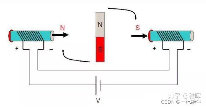
For a simplified brushless motor , With Three phase two pole inner rotor motor For example , The three-phase windings of the stator have Star connection The way and Triangular connection The way , and Two two conduction mode of three-phase star connection Most commonly used , Here is a simple analysis with this model :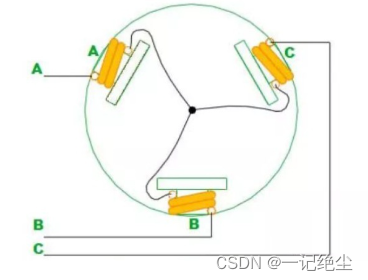
As shown in the figure above , The three-phase connection mode of brushless motor is Each phase leads out one end of the conductor , And the other end is connected with the other two . In this case, if we are right A、B Positive voltage and negative voltage are applied to the poles respectively , Then the direction of the magnetic pole of the coil can be judged by the right-hand screw rule, as shown in the figure below :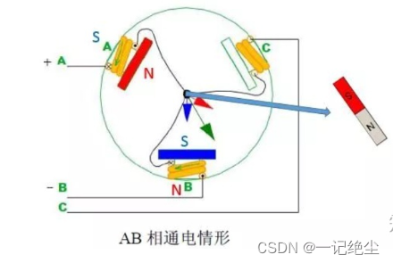
Think about the angle at which the rotor in the middle receives the maximum torque ?
Yes, it's with CO(O For the center ) When the lines are parallel , The magnet will be subjected to A、B The two magnetic poles push and pull , Until it rotates to and AB The wires are parallel and the magnet Internal magnetic lines of force Direction and AB When the direction of the magnetic lines of force is consistent , The closing moment is 0 And stable , That is, the state on the right in the above figure . let me put it another way ,AB Connecting electricity will make the rotor try to turn to the state on the right in the above figure . as for C It doesn't work for the time being .
Empathy , Let's change to AC Connect electricity , At this time, the rotor will tend to turn to the horizontal angle on the right of the figure below :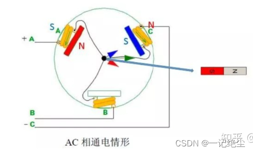
then BC Connect electricity :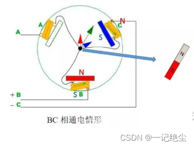
…
And so on , You can get the angle of the rotor under each power on state , It's in the picture below 6 Status , Each state is separated 60 degree ,6 The complete rotation is completed in one process , Were conducted 6 Secondary commutation :

The whole process is like riding on a donkey and hanging a carrot , The rotating magnetic field pulls the permanent magnet to rotate constantly :
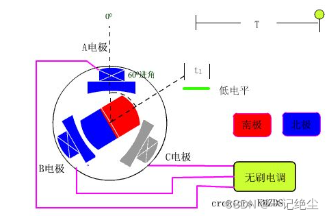
And this reversing operation , It needs a drive to complete .
This is also No brush motor and Brush motors The biggest difference , That is, unlike the mechanical commutation of a brush motor , Brushless motor drives the rotor to rotate continuously through electronic commutation , Motor voltage and KV The value determines the motor speed , The speed of the motor determines the frequency of commutation .
As for when and how to know which power supply phase to change ? How to produce smoother commutation voltage ? How to improve the utilization efficiency of power supply ? These are all FOC Problems to be discussed and solved in control methods .
1.3 About BLDC and PMSM The difference between
Brushless motor can be divided into Brushless DC motor (BLDC, We all use this on our model aircraft ) And permanent magnet synchronous motor (PMSM), The structure is similar , The main difference lies in the manufacturing method ( Coil winding mode ) Some characteristic differences caused by different ( For example, the waveform of back EMF ).
From the brushless motor model analyzed above, we can see , Because the rotor has only 6 A stable state , Therefore, the rotation process is actually not smooth , There is torque jitter ( When there is no power on, you can turn the brushless motor by hand , Will feel this “ Granular sense ”). So in order to solve this problem , from “ Hardware ” And from the “ Software ” There are two solutions for departure , And that leads to BLDC and PMSM The difference between .
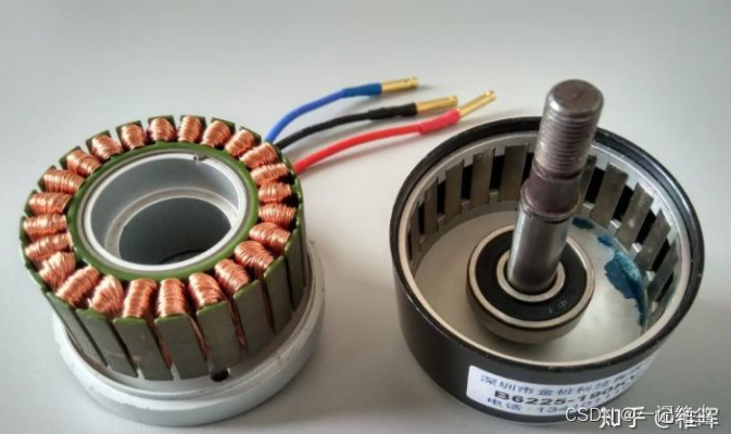
In short ,BLDC Because the back EMF is close to the trapezoidal wave , So there must be the jitter problem mentioned above , But turn around and shake 6 It's too obvious , If I add motor slots 、 Polar logarithm ( That is, the number of magnets ), That used to be 360 Du Nei trembles 6 Next , Now become 120 Du Nei trembles 6 Next , Even smaller , such “ Granular sense ” It becomes smaller ? Actually bought BLDC Motors are basically multipole ( For example, below ), The principle is the same as the previous analysis , What comes out is all three-phase signals ( The three lines in the figure ), You can analogize yourself .BLDC It can also be combined with anti cogging Algorithm FOC Carry out torque compensation to realize smooth control .
And on the other hand , Why do we have to use square wave This kind of uneven wave drives the motor , use Sine wave Doesn't it smell good ? Yes , This is it. PMSM The way to solve the problem , because PMSM The back EMF of is designed in the shape of a sine wave , We use it Software and algorithms combination PWM Technology converts square waves into equivalent SPWM Sine wave or SVPWM Ma Anbo , Then drive the motor , The result is delicious , The control effect is ideal . Of course, in order to produce better waveforms 、 Better rotating magnetic field , Driver 、 The control algorithm becomes very complex , this It's also FOC Implementation principle of , More on that later .
1.4 Drive circuit implementation
The drive circuit of brushless motor mainly uses three-phase inverter circuit , Here's the picture :
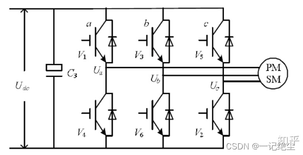
So-called Inverter circuit , Namely the Direct current Transformation for Alternating current (ac) , Or simply a circuit that can generate different current flows , We can also see from the previous motor model analysis , For brushless motor drive, it is necessary to apply voltage in different directions at different times ( electric current ) Of , Therefore, inverter circuit is needed .
The specific implementation of the inverter circuit is generally Half bridge MOS circuit To make . The prototype of half bridge circuit is as follows , It's very simple , That's the two one. MOS Composed of tubes Upper bridge arm and Lower arm , An output line is led out in the middle :
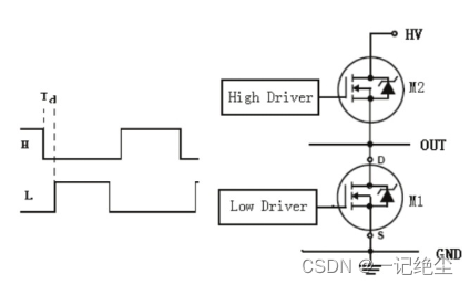
use 3 A half bridge circuit can be combined into a three-phase inverter circuit , An output line from each half bridge is connected to a phase line of the brushless motor , The most basic brushless drive circuit is completed .
In principle ,MOS The tube can be regarded as a high-speed electronic switch controlled by voltage , stay MOS The grid of the tube ( In the picture above High Drive and Low Drive) Apply high level or low level , You can control MOS Turn on or off the source and drain . For example, in the figure below , We open the upper arm of the first half bridge 、 The lower bridge arms of the second and third half bridges ( The rest are closed ), Then you can make the current Flow through the motor from the positive pole of the power supply a phase , Flow through b、c phase , Then return to the negative pole of the power supply :
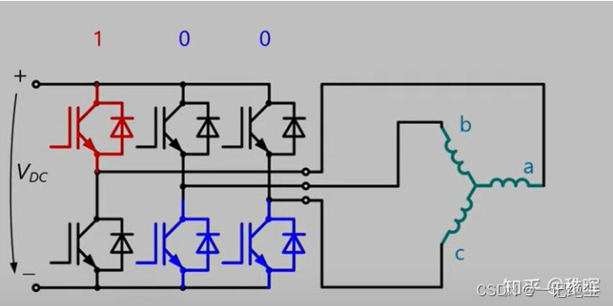
So by controlling the different switch states of the three half bridges , We can control the different flow of current in the motor .
 Be careful , In this circuit , In each state, the three-phase coil of the motor will have current ;
 In the example in the previous section, we will only make two-phase coils have current at the same time , The other phase doesn't work .
 So what is the reason for this modification ? Certainly : What a shame to waste ~
 If you waste one phase and don't use it, you will lose some torque in vain ? The driving principle through the way in the above figure is also consistent with the previous analysis ,
 But it can produce more torque , So of course it's a better choice .
Next, we will encode the state of the half bridge circuit , First, there are only two states for a half bridge :
The upper bridge is opened and the lower bridge is closed, which is defined as the state 1
The upper bridge is closed and the lower bridge is opened, which is defined as the state 0
such , There are three groups and a half bridges 8 Combination mode , The codes are :000、001、010、011、100、101、110、111, Remember that , It will be used later
 Someone might ask , Why can only one of the upper and lower bridge arms of a half bridge be connected ? It can't be closed or connected ??
 harm , Just think about it , It is obviously impossible to connect up and down , Because this is equivalent to short circuiting the power supply ...
 It's disconnected up and down ? Don't need to, , Because this brings us back to the above mentioned , At this time, one phase of the motor does not work , A waste .
 In fact, the implementation of half bridge drive circuit will be more complex than the above analysis ,
 For example, we need to consider the switching frequency of the switch 、 The opening and closing times are asymmetric 、 Dead zone problem and so on ,
 I designed it later FOC The drive uses a special half axle MOS Grid drive IC To achieve .
1.5 Waveform of rotating three-phase motor
According to the basic model of brushless motor , Suppose we get such a motor , Manually rotate its rotor at a uniform speed , Then observe its three-phase output voltage with an oscilloscope ( That is, the voltage generated by the back EMF ), What waveform will you see ?
In fact, it's natural to think , We will get 3 Root sine curve , And the phase difference between two of the three curves is 120°:
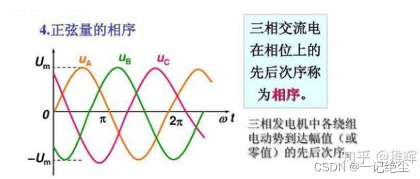
In fact, the power generation principle of three-phase generator is like this , The output is three-phase amplitude 220V The alternating current of ( The line voltage is 380V, namely [ The formula ] V).
The generator in turn is the motor , So if we input the above three-phase sinusoidal voltage on the three-phase coil of the three-phase brushless motor in reverse , Then the brushless motor can be driven to rotate smoothly and efficiently .
And this is also FOC The basic means of driving brushless motor , That is, by calculating the required voltage vector , Use SVPWM Technology generates debug signals , Drive three-phase inverter circuit , The equivalent three-phase sinusoidal voltage drive motor is synthesized .
2. FOC Control principle
Everyone is just beginning to contact FOC When consulting relevant documents , May feel a little dizzy :
Why should we do all kinds of transformations and inverse transformations ?
What exactly does space vector represent ??
Why does this state switching sequence have to be in different sectors ???
…
2.1 FOC Algorithm Pipeline
So let's see FOC The whole process of control :
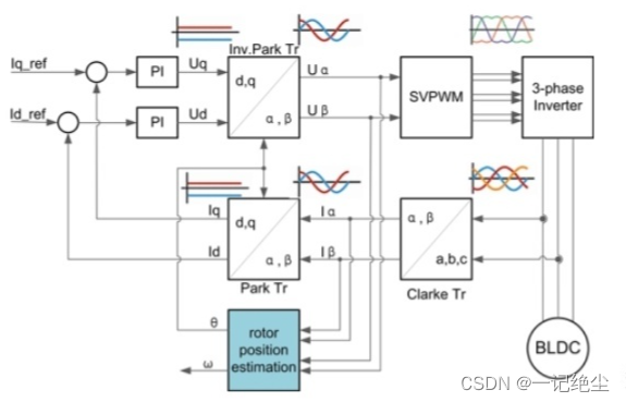
Explain a little , This figure takes current closed-loop control as an example , That is, let the motor always produce a constant torque ( That is, a constant current , Because the torque is proportional to the current ).
You can see that the input of the controller is the leftmost Iq_ref and Id_ref, Two variables pass PID The controller performs feedback adjustment , It also involves several transformation modules , Yes Park Transform sum Clark Transformation ; Finally, through the above mentioned SVPWM The module acts on the three-phase inverter to control the motor ; and PID Feedback quantity of controller , It is the sampling value of the motor output current .
It doesn't matter if the above process is not easy to understand , First, let's summarize ,FOC The whole process of control is like this :
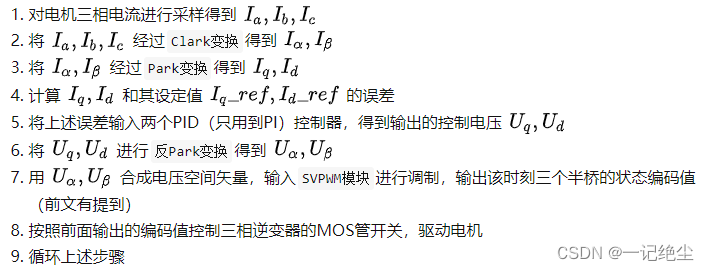
Now let's introduce the specific operation and significance of each step .
2.2 Clark Transform with Park Transformation
I analyzed it earlier , If you want to drive the three-phase motor smoothly , We need to generate three phase differences 120 Degree sine wave , But we The ultimate control object is MOS Opening and closing of tubes , Only the maximum voltage and 0 It's worth two states , How to generate continuous sine waves ?
by the way , Use the above mentioned PWM Technology can do , So-called SPWM That's what we did , Here's the picture :
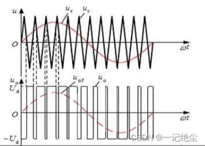
Let's observe the waveform in the figure above , We use the intersection of sine wave and triangular wave in the above coordinate system to project to the lower coordinate axis , To determine PWM The duty cycle of , Synthesized in this way PWM wave , After passing through the low-pass filter , In fact, it is equivalent to a sine wave ! therefore SPWM Is in the PWM On the basis of the sine wave, the square wave with the regular change of sine wave is modulated and synthesized .
however SPWM The debugging mode is FOC Not often used in implementations , as a result of SPWM It's more important than what I want to say later SVPWM The utilization rate of bus voltage should be low 15%.
On the other hand , From a control point of view , We don't even want to deal with three sine waves !
Because to accurately control the nonlinear signal, it is necessary to use a complex high-order controller , This is important for modeling costs 、 Processor computing power 、 Real time control is unfavorable . In a nutshell , The feedback input variables of our controller are not three current sampling values , It's too troublesome for you to ask me to track three sine waves steadily ! Can you simply track a straight line ( Constant ) ah ?
The answer is yes ~ Just apply a little math tricks
Clark Transformation
Let's go back up there FOC Control process 9 A step Of the 1 Step , That is to sample the three phase currents of the motor , In this step, the sampling resistor in series will be used (Shunt) Conduct current sampling .
Because the current of the motor is usually very large , So the resistance value of the sampling resistance is very small , Even close to the resistance of the wire , So the actual sampling circuit PCB There are also some stresses in the design , For example, use Kelvin connection (Kelvin connections).
But we can not use three samplers in actual circuit design ( There is actually a single sampling resistor 、 Double sampling resistance and three sampling resistance connection ), Only two are enough . Because the Kirchhoff's current law (KCL), At any moment , The sum of the current flowing into the node is equal to the sum of the current flowing out of the node , in other words
I a + I b + I c = 0 I_a+I_b+I_c=0 Ia+Ib+Ic=0
You only need to know two of them to calculate the third .
These three currents are basically three phase differences 120 Degree sine wave , Before inputting these signals into the controller for feedback control , Let's play some math games first :
We know the three-phase coordinate system ( I a , I b , I c ) (I_a, I_b, I_c) (Ia,Ib,Ic) as follows :
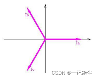
problem : This is clearly a coordinate system in a two-dimensional plane , Why want to use 3 Coordinate axes ?
And obviously ( I a , I b , I c ) (I_a, I_b, I_c) (Ia,Ib,Ic) These three basis vectors are non orthogonal , Students who have studied linear algebra may think , We can do a very simple base transformation to orthogonalize it into a rectangular coordinate system , We name the new rectangular coordinate system α , β \alpha, \beta α,β Coordinate system , The transformation formula is as follows :

In fact, it is a very simple calculation of coordinate axis projection , Written in matrix form as follows

So we return to the rectangular coordinate system , Are you very happy , The waveforms before and after transformation are as follows :

It can be seen that after transformation, it is still a sine wave … It's just that we lack a variable that needs to be controlled , Now just control I α , I β I_\alpha,I_\beta Iα,Iβ These two variables , The motor rotation can be controlled by making it meet the waveform change law below the figure above 了 , The frequency remains constant .
- Notice the I α , I β I_\alpha,I_\beta Iα,Iβ It's our virtual variable , So in calculating a group I α , I β I_\alpha,I_\beta Iα,Iβ after , We use the reverse transformation formula of the above formula to transform it back and apply it to the three phases of the motor .
Is this ?
Of course not. , If it's just to reduce a control variable, this Transformation / Reverse transformation The operation is obviously a little superfluous .
Interestingly, we can also change : although I α , I β I_\alpha,I_\beta Iα,Iβ One dimensional variables are missing in the coordinate system , But the new variable is still nonlinear ( sine ), Is there any way to linearize them ? yes , we have ,Park Transformation is the job .
Park Transformation
In this step, we continue Clark Transformation take I α − I β I_\alpha-I_\beta Iα−Iβ Coordinate system rotation θ \theta θ degree , among θ \theta θ Is the current angle of the rotor , Here's the picture :
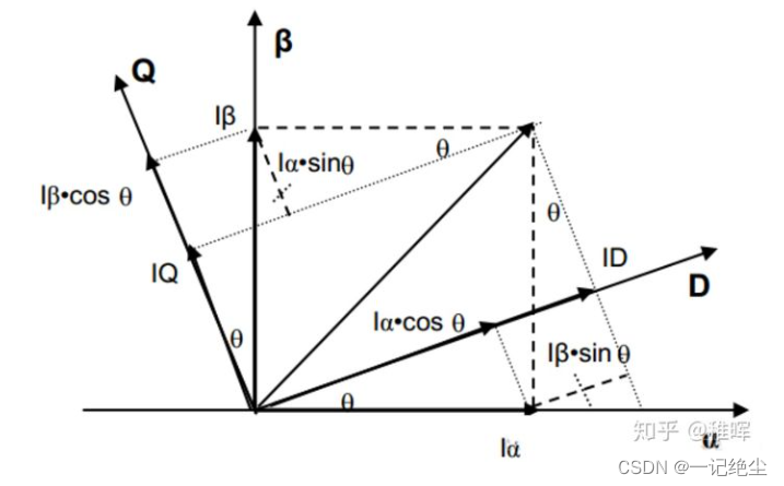
The transformation formula is as follows :

It's also very simple. , Is to act on a rotation matrix , In matrix form :

in other words , This d − q d-q d−q The coordinate system always rotates with the rotor !
This operation is feasible , Because we will input the real-time rotation angle of the rotor through the encoder , So this angle Always a known number . After this step of transformation , We will find that , A uniform rotation vector becomes a constant value in this coordinate system !( Obviously , Because the reference frame is stationary relative to the vector ), In this coordinate system, both control variables are linearized !

Next, if we take I q , I d I_q,I_d Iq,Id These two values are the object of feedback control , Then it is obvious that some linear controllers can be used for control , such as PID( Yes , Although there are many cool advanced control methods in academia , But industry still prefers PID).
So far, we have understood the above FOC Control process 9 A step Before 3 Step .
2.3 PID control
PID( The proportion 、 integral 、 differential ) What is control? This article will not explain more , The foundation in the foundation , There are also many articles to introduce , Those who are not familiar with it can search relevant information by themselves .
stay FOC Three are mainly used in control PID Ring , From the inner ring to the outer ring is : Current loop 、 Speed loop 、 Position loop .
in other words : We control the motor current through current feedback ( torque ) -> then Control the speed of the motor by controlling the torque -> Re pass Control the speed of the motor and the position of the motor .
The current exchange control block diagram of the innermost loop is as follows :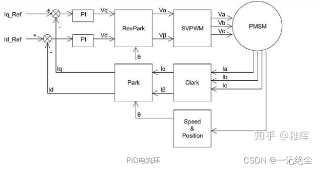
You can see it , This is what I mentioned earlier FOC control 9 The process described in step . Actually only used PI control , Differential is not introduced , Because if you deduce the transfer function of voltage and current, you will find that this is actually a first-order inertia link ( And in fact, we can simplify it by zero pole cancellation PI Parameters , You only need to control one parameter, that is, current bandwidth ).
In the picture above Speed & Position The module can be an encoder , Or Hall sensor and other sensors that can sense the rotor position .
In particular, one of them I q , I d , I q r e f , I d r e f I_q,I_d,I_qref,I_dref Iq,Id,Iqref,Idref, The first two are known through Clark Transform sum Park Transformed , The latter two are the values we expect the first two to achieve , What physical quantity does this value represent ? Refer to the figure below :
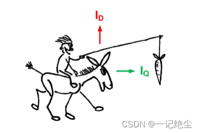
That is to say, we will realize the coupling of rotor flux linkage in one pass , It is decomposed into radial and tangential variables of rotor rotation :
- among I q I_q Iq That's what we need , Represents the desired torque output
- and I d I_d Id It's something we don't need , We hope to control it as 0
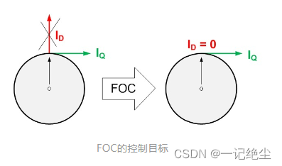
adopt PID The controller uses the above inputs ( Current sampling value 、 Encoder position ) And the output (MOS Tube switch status ) Complete the closed-loop control of motor current .
Then go to the next level of speed loop :
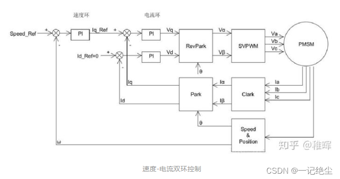
In the diagram above , S p e e d r e f Speed_{ref} Speedref Is the speed setpoint , w w w It is the speed feedback of the motor , It can be calculated by motor encoder or Hall Sensor , Still in use PI control .
The calculated motor speed w w w And speed setting S p e e d r e f Speed_{ref} Speedref Calculate the error value , Substitution speed PI Ring , The result of calculation is used as the input of current loop , Speed is achieved - Double closed loop control of current .
The outermost layer is the position ring , That is, it can control the motor to rotate to a precise angle and maintain , The control block diagram is as follows :
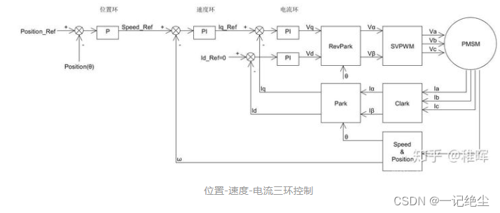
Similarly, it should be very simple and understandable , Position control in the figure above PID It only took P term ( You can also use PI).
In practical use , Because the encoder cannot directly return the motor speed w w w, Therefore, the speed of the motor can be expressed by calculating the change of the coding value within a certain period of time ( That is, the average speed represents the instantaneous speed ). When the motor speed is relatively high , This way is OK ; But in position control mode , The speed of the motor will be very slow ( Because the rotor is required to be fixed in a certain position ), At this time, there will be a very large error in using the average speed measurement method ( The rotor does not move or moves very slowly , The encoder has no output or only outputs 1、2 Pulse ).
So in order to avoid the error caused by the speed link , When doing position control, you can only use the double loop composed of position and current to control , But at this time, we need to make some changes to the position ring , The control block diagram is as follows :
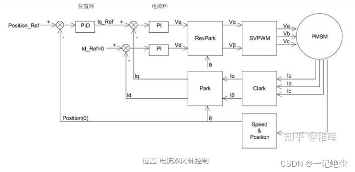
Because the speed ring is removed , Here we use the complete position ring PID control , That is, add the differential term ( Because the differential of position is velocity , This can reduce the oscillation of position control and speed up convergence ; The function of integral term is to eliminate static error ).
Okay , So far, the whole control circuit is basically clear , But there are some details we haven't covered , It is in the above block diagram SVPWM modular .
Careful students will find , In the whole control flow chart Park Transformation and corresponding inverse Park Transformation , But it didn't Clark Transform the corresponding inverse Clark Transformation , Instead, a SVPWM modular .
The following will be true of SVPWM Technology in detail .
2.4 Space voltage vector
What is space voltage vector ?
Space voltage vector is a virtual vector in the process of controlling motor , Since it's a vector , Nature has size and direction , So what is its size and direction ?
Or the front Three phase inverter drive circuit The state in that picture is an example , Input 100 The state of :
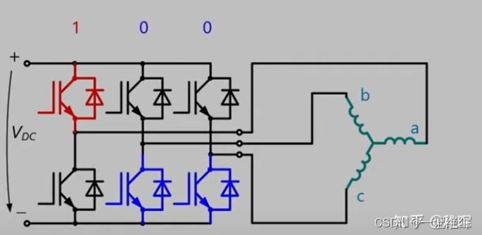
At this time, the equivalent circuit is shown in the figure :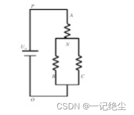
Therefore, in the motor Three phase voltage ( Phase voltage is the voltage of each phase relative to the intermediate connection point of the motor ) It can be expressed as :
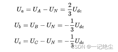
In fact, it is the simplest voltage dividing circuit , among U d c U_{dc} Udc Is the bus voltage , That is, the power supply voltage .
If we specify that the direction pointing to the center is positive , Whereas negative , At this time, we can draw the three voltage vectors in the figure below 


Combined with the analysis of the previous chapters , The rotor permanent magnet will try to rotate to the same direction as the internal magnetic line of force and the external magnetic field , So this vector In fact, it can represent the direction we want the rotor to rotate , That is, the direction of the magnetic field to be generated . And this vector will continue to rotate in space , Its amplitude remains unchanged , Is the peak value of phase voltage U d c U_dc Udc, And at angular velocity w = 2 π f w=2\pi f w=2πf Rotate at a constant speed .
We will see later ,SVPWM The purpose of the algorithm , It uses the switching state of the three-phase bridge to rotate in space The vector is expressed , We call this vector Space voltage vector .
If expressed by mathematical formula, it is :

In order to study the space voltage vector output by the inverter when the upper and lower bridge arms of each phase are combined with different switches , We define switching functions
S x ( x ∈ a , b , c ) S_x(x\in a,b,c) Sx(x∈a,b,c) by :
The upper bridge arm is connected and the lower bridge arm is connected

And two zero vectors :
It can be seen that the voltage between the three phases of the motor is 0 No torque ( Do not consider back EMF ).
Next, take one of the switch combinations as an example , hypothesis S x = U 4 ( 100 ) S_x=U_4(100) Sx=U4(100), That is, the state in this figure :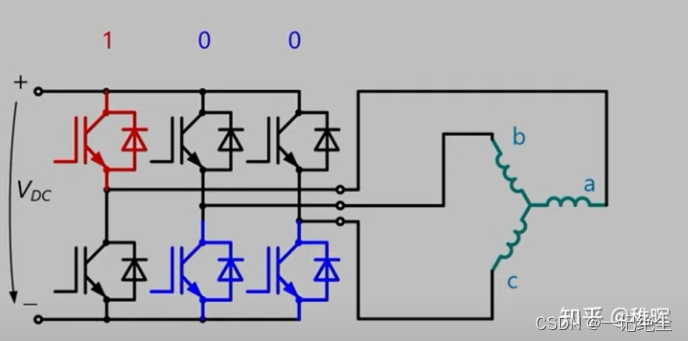
As the previous analysis , At this time, the voltage vector is AO Direction , The size is U d c U_{dc} Udc, We draw this vector on the coordinate axis, as shown in the figure :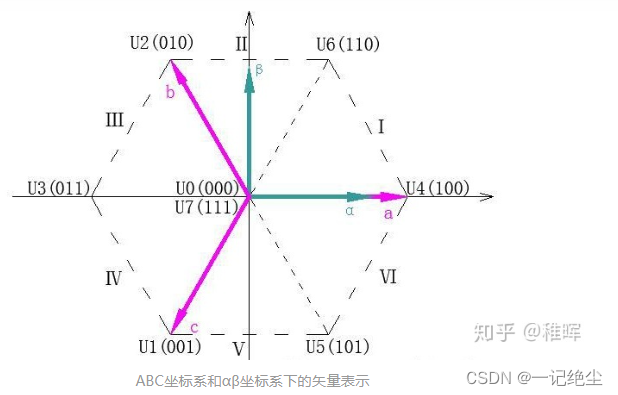
- Notice... In the picture above (100) Vector direction and AO The direction is the opposite ( become OA Direction ), This is related to the definition of positive direction , Such regulations are more intuitive .
At the same time, you can notice that the two zero vectors actually coincide with the origin , Because the magnetic field generating torque in the motor in these two states is 0( Do not consider the resistance torque generated by the back electromotive force in the process of rotation ).
Empathy , The rest can be seen in the above figure 5 Space voltage vector , Their endpoints form a regular hexagon , At the same time, the plane is divided into six sectors ( That's what this is Ⅰ、Ⅱ、Ⅲ、Ⅳ、Ⅴ、Ⅵ).
So here comes the problem : From here 6 A space voltage vector can only generate 6 Torque in two directions , How can we generate torque in any direction ?
2.5 SVPWM technology
Since it is “ vector control ”, Of course, there is a way , The answer is : Use this 6 Space voltage vectors are used as basis vectors to synthesize arbitrary vectors . In every sector , Select two adjacent voltage vectors and zero vector , according to Volt second balance principle To synthesize any voltage vector in each sector , namely :
After discretization, it is equivalent to the following formula :

In the formula U r e f U_{ref} Uref Is the voltage vector we expect ,T It's a PWM cycle .

So the meaning of the above formula is : We can periodically switch between different space voltage vectors , As long as the duty cycle of different basis vectors in a cycle is reasonably configured , The equivalent arbitrary space voltage vector can be synthesized .
Is it with PWM Their thoughts are exactly the same , This is why this method is called SVPWM( Space voltage vector pulse width modulation ).
Let's take a chestnut , Suppose we want to synthesize the U r e f U_{ref} Uref, stay Ⅰ A sector :
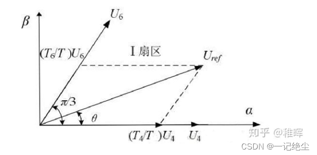
Obviously we can go through U 4 U_4 U4 and U 6 U_6 U6 To synthesize U r e f U_{ref} Uref, Then the picture will U r e f U_{ref} Uref The projection is decomposed to U 4 U_4 U4 and U 6 U_6 U6 The direction of , According to sine theorem :
Again because ∣ U 4 ∣ = ∣ U 6 ∣ = 2 3 U d c |U_4|=|U_6|=\frac{2}{3}U_{dc} ∣U4∣=∣U6∣=32Udc, So we can calculate T 4 T_4 T4 and T 6 T_6 T6:
among m by SVPWM Modulation coefficient of ( Modulation ratio ):

- Obviously, in the process of current loop control m The larger the setting, the greater the expected torque .
The time allocated by the zero vector is : T 0 = T 7 = 1 2 ( T − T 4 − T 6 ) T_0=T_7=\frac{1}{2}(T-T_4-T_6) T0=T7=21(T−T4−T6)
Why? T 0 = T 7 T_0=T_7 T0=T7 ? This is what we will PWM The waveform is set as the result of symmetrical configuration of zero vector in the central alignment mode , It will be mentioned later .
Now we have the duration of all States in a cycle , There is still one order to go , That is to say, each of them The order of state switching .
- problem : Isn't any order ok ? Anyway, it's doing integral , What matters is duration, not sequence , How to switch in a cycle .
Yes , Theoretically, any switching order is ok Of , But in practice, we need to consider more restrictions , Such as because MOS There is switching loss in the tube , We hope to minimize MOS Switching times of tubes , Then the purpose is to minimize the switching loss , We can design the following switching sequence :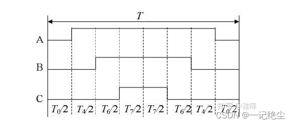
You can see it in the picture above , At each state switch , Only one phase has changed :000->100->110->111->110->100->000, This is also the so-called seven paragraph pattern SVPWM Modulation method .
At the same time, we insert two zero vectors in a reasonable position , And the zero vector is evenly distributed in time , So as to produce PWM symmetry , Thus effectively reducing PWM Harmonic component of .
Empathy , We can also list the switching order in other sectors :

thus ,SVPWM My work is done , We get the space voltage vectors needed at each moment and their duration , The capture comparison register assigned to the corresponding channel in the processor generates the corresponding three PWM wave form , control MOS Tube switch , And then produce the voltage we expect 、 electric current 、 Moment .
3. summary
thus FOC The principle of and the whole control link are finished , Think back to the whole process , Try to answer the question mentioned at the beginning : Why is it FOC There are so many transformations and inverse transformations in control ?
Because of the so-called “ vector control ” It's just doing decoupling , Decouple the mutual coupled three-phase flux linkage into an quadrature axis that is easy to control I q I_q Iq And straight axis I d I_d Id . The whole process is like when we are doing signal processing , adopt FFT Transform the signal to the frequency domain for processing, and then IFFT Inverse transformation back to time domain is a truth .
Another thing worth mentioning , This article introduces Feeling Of FOC Control method , Actually FOC It can be done Senseless control ( That is, there is no need for additional sensors such as encoders ), Of course, the control algorithm will be more complex , Need to introduce feedforward control 、 Concepts such as observer , The advantage of insensibility is that the structure installation is simpler , It can avoid the risk of position sensor failure, etc .
Reprint Zhi Huijun's article :
link : 【 self-control FOC Driver 】 Explain in simple terms FOC Algorithm and SVPWM technology
边栏推荐
- ZABBIX monitoring system custom monitoring content
- Need help resetting PHP counters - PHP
- Const string inside function - C #
- Take you to master the formatter of visual studio code
- How to use MOS tube to realize the anti reverse connection circuit of power supply
- [gurobi] establishment of simple model
- 没有Kubernetes怎么玩Dapr?
- deno debugger
- Activiti常見操作數據錶關系
- How to set multiple selecteditems on a list box- c#
猜你喜欢
![[go basics] 2 - go basic sentences](/img/b1/961615b439d75679a3bb40a60f208d.png)
[go basics] 2 - go basic sentences
广和通高性能4G/5G无线模组解决方案全面推动高效、低碳智能电网
Chrome is set to pure black

snipaste 方便的截图软件,可以复制在屏幕上
Question 49: how to quickly determine the impact of IO latency on MySQL performance

ES6 summary
SSRF vulnerability exploitation - attack redis
Common components of flask
![[gurobi] establishment of simple model](/img/3f/d637406bca3888b939bead40b24337.png)
[gurobi] establishment of simple model

AcWing 244. Enigmatic cow (tree array + binary search)
随机推荐
Question 49: how to quickly determine the impact of IO latency on MySQL performance
OKR vs. KPI figure out these two concepts at once!
Common components of flask
Sort by item from the list within the list - C #
Group programming ladder race - exercise set l2-002 linked list de duplication
1、卡尔曼滤波-最佳的线性滤波器
Project 1 household accounting software (goal + demand description + code explanation + basic fund and revenue and expenditure details record + realization of keyboard access)
Learn nuxt js
How to set multiple selecteditems on a list box- c#
AcWing 244. Enigmatic cow (tree array + binary search)
根据数字显示中文汉字
Leetcode 146. LRU 缓存
Comprendre la méthode de détection des valeurs aberrantes des données
Three paradigms of database design
[go basics] 1 - go go
Système de surveillance zabbix contenu de surveillance personnalisé
Application of isnull in database query
如何用MOS管来实现电源防反接电路
DM database password policy and login restriction settings
Oracle-存储过程与函数