当前位置:网站首页>Canoe - the second simulation project -xvihicle1 bus database design (operation)
Canoe - the second simulation project -xvihicle1 bus database design (operation)
2022-07-04 10:50:00 【picoasis】
This article records the operation steps of configuration , Please refer to :https://blog.csdn.net/lamanchas/article/details/122105365
The original content comes from 《CANoe Development from entry to mastery 》. The software version is CANoe12.0
Catalog
1. New project & Engineering structure folder
2. New database & Bus description
be based on CAN Template new database
Bus description ——Networks( Configure bus name , type )
3. node : Add a node description to the database ——Network Nodes
establish Network Nodes node , Set node properties
4. Communication signals ( message , The signal ):
message ——Message——CAN Uploaded data
To configure Message attribute
Signal configuration information
The signal Signal Associated message Message:
Configure the sending and receiving of signals at different nodes :
Signal Attribute interpretation :
environment variable Environment Variables
Environment variable configuration
Description of the meaning of environment variable attributes :
Environment variable ValueTabe To configure
5. Database engineering XVehicle.dbc Import project file
1. New project & Engineering structure folder
New project
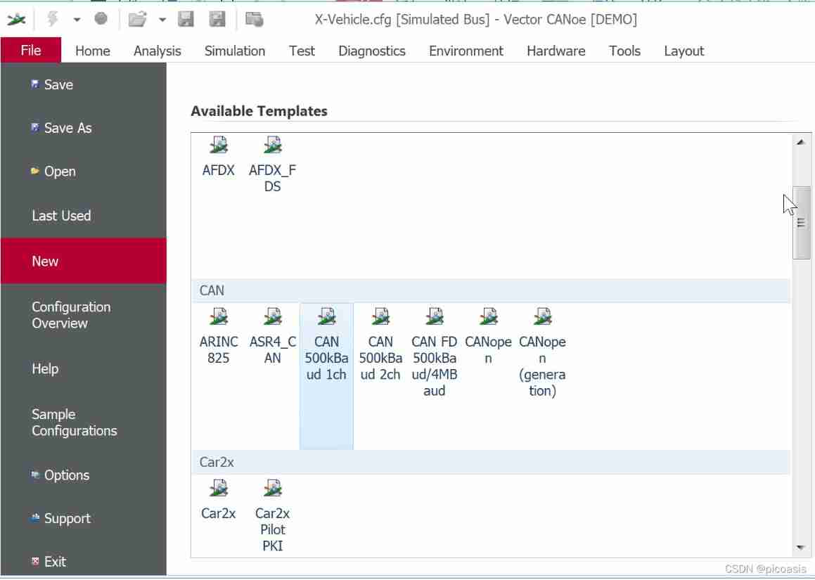
File——New——CAN500kBaud 1ch
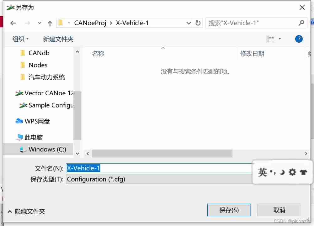
File——Save ——X-Vehicle-1( Save in folder X-Vehicle-1 Next )
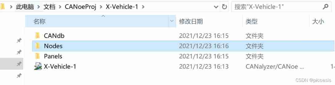
Engineering structure folder
In the folder X-Vehicle-1 Next , Create project directory folder CANdb,Nodes,Panels:
2. New database & Bus description
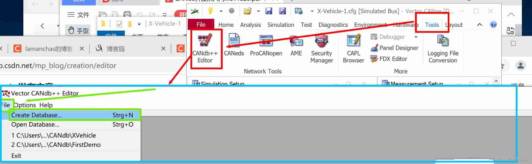
be based on CAN Template new database
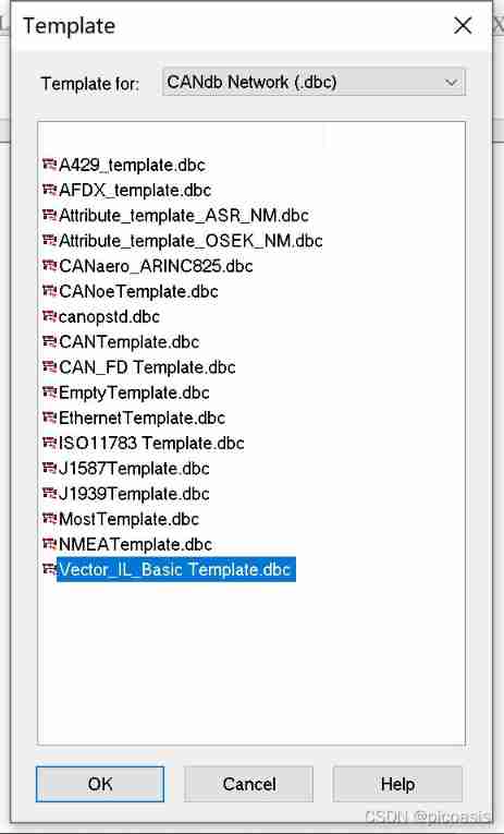
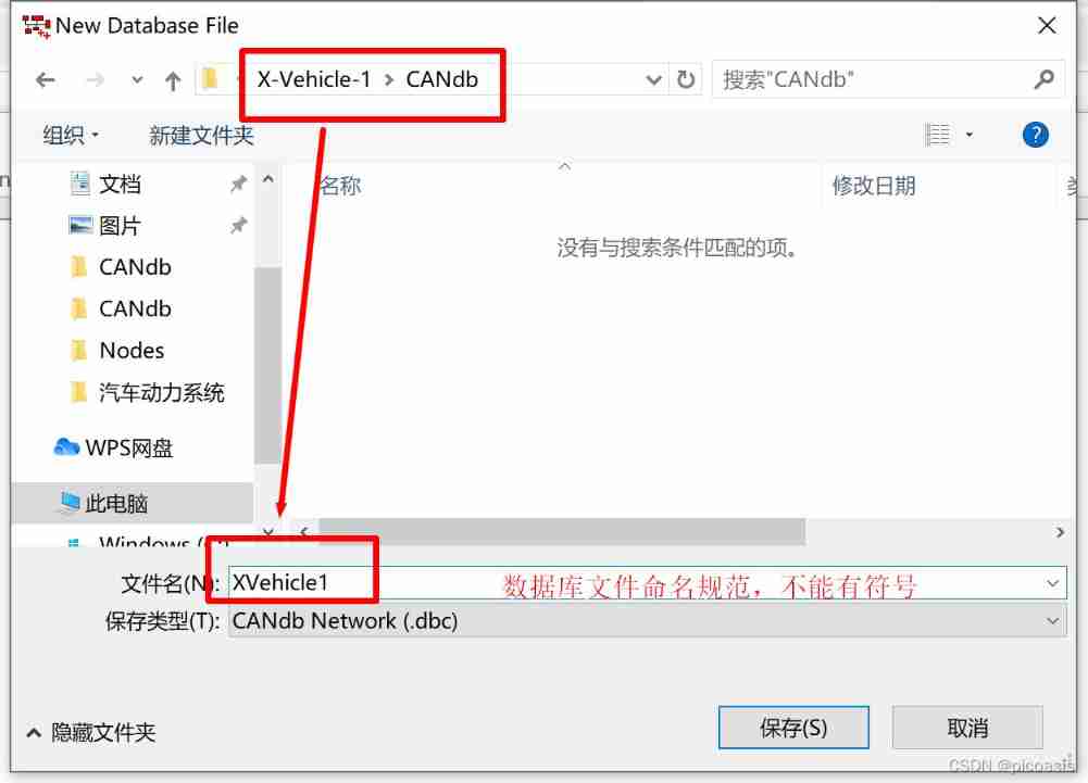
Tools-CANdb++ Editor——File——CreateDatabase—— Select the bus template according to the function ( This article chooses Vector IL Basic Template.dbc)—— Create a database project XVehicle.dbc】
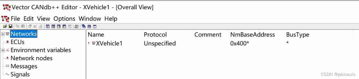
After creating a new template ,CANdb++Editor The navigation area of the will show the relationship between all objects in the network .
The navigation area automatically lists the current bus network architecture and pairs like , contain Networks、(ECUs、Network nodes)、(Environment variables、Messages and Signals).
Bus description ——Networks( Configure bus name , type )
stay Networks( The Internet ) Under a , List the bus networks currently simulated .
There can be multiple networks in the database , Each network consists of one or more ECU form ,ECU Through network nodes Communicate with each other .
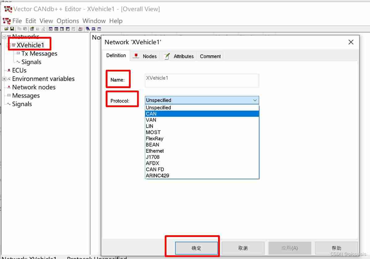
Different vehicle manufacturers have different requirements for the whole vehicle individual CAN Name definitions are different , for example ,PowerTrain CAN、Body CAN、Comfort CAN etc. .
This chapter defines the network name as XVehicle1, The type is CAN. ( Right click XVehicle1, choice Edit Network Enter bus attribute editing , As shown in the figure below .
3. node : Add a node description to the database ——Network Nodes
stay ECUs( Electronic control unit ) Under a , Lists the electronic control units contained in the current network , They pass through Network nodes (Network Nodes) Realize the interaction of information . Usually ,ECU It corresponds to the network nodes one by one Of . When ECU As a gateway , One ECU It can contain multiple network nodes . stay CAN In the database , Double click a individual ECU You can see the ECU Corresponding network nodes and environment variables .
What we need to remind readers is , stay CAN The database cannot be created directly ECU,CANdb++ Will be creating Network nodes ——Network Nodes At the same time , Create a with the same name ECU.
So we create Network Nodes To create control panel nodes , The system automatically creates penel Corresponding simulation node .
establish Network Nodes node , Set node properties
Network Nodes( Network nodes ) yes ECUs Communication interface , various ECU adopt Network Nodes Realization Sending and receiving information on the bus , Every Network Nodes Include the corresponding name and address . Right click in the navigation area Network Nodes, In the shortcut menu, select Create a new one named Engine Network nodes of , And set the address of the node to 0x1, As shown in the figure .
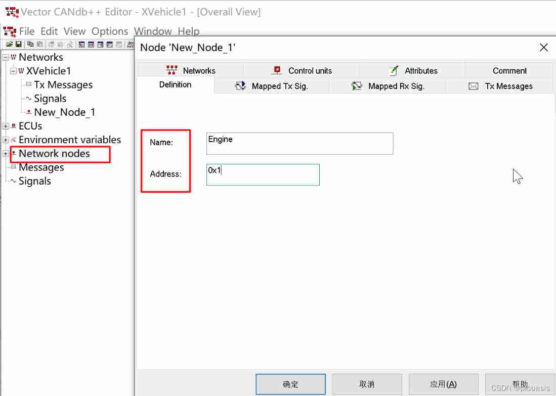
In the same way , Create another one called Door The node of ( The address is Ox2) And a name called Display The node of ( The address is 0x3).
After creation , You can see that the system automatically generates the corresponding ECU node , Respectively in NetWorks and ECUs There's a show in all of them .

4. Communication signals ( message , The signal ):
message ——Message——CAN Uploaded data
Messages( message ) It is the data that the nodes on the bus communicate with each other .
In the database , Each message shall contain the following attributes ( The messages used in this example are CAN As defined in the specification document CAN2.0A standard CAN). You can press the following 4 Understand memory by classification :
- 【 Message structure 】:Name( Message name ) CAN ID(CAN identifier ) DLC(Data Length Code, Data length ) Type( Transfer type ) Cycle Time( cycle )
- 【 Included content 】:Signals( The signal )
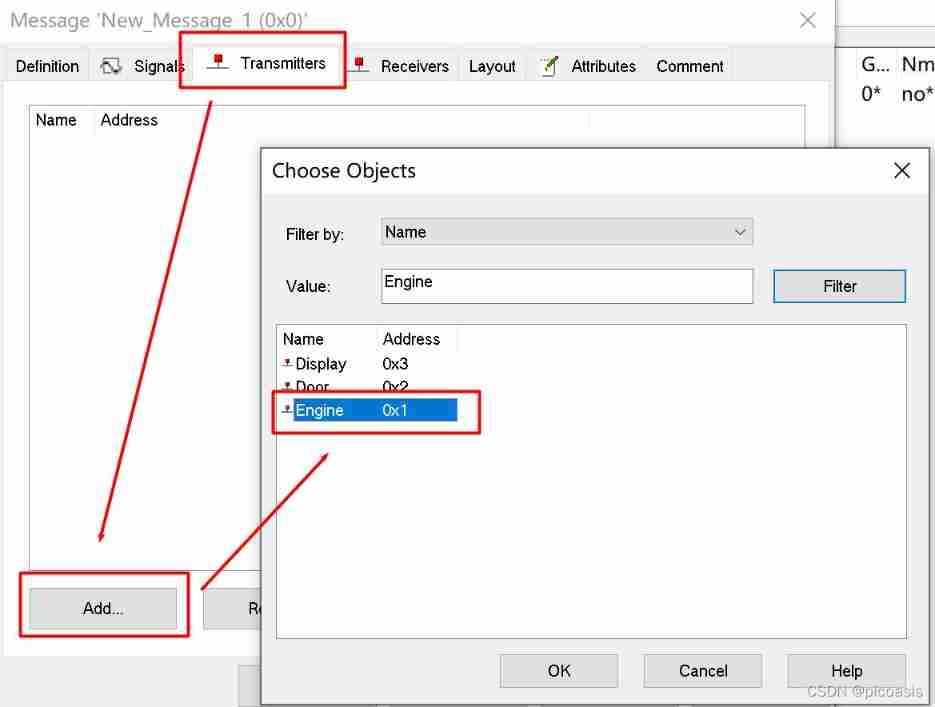
- 【 Transceiver node 】Transmitters( Sending node ) Receivers( Receiving node )
- 【 other 】: Layout( Layout ) Attributes( General properties ) Comment( explain )
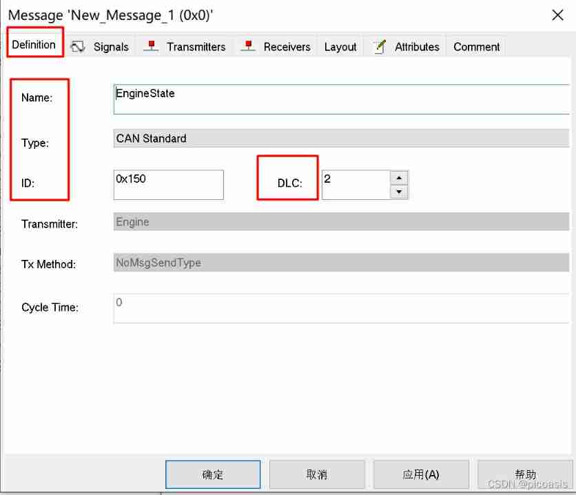
To configure Message attribute
X-Vehicle-1 In Engineering , There are two kinds of messages :DoorState,EngineState. Create messages and set corresponding attributes :
| Name | CAN ID | DLC | Type | Transmitters | Receivers | GenMsgCycleTime | GenMsgSendType |
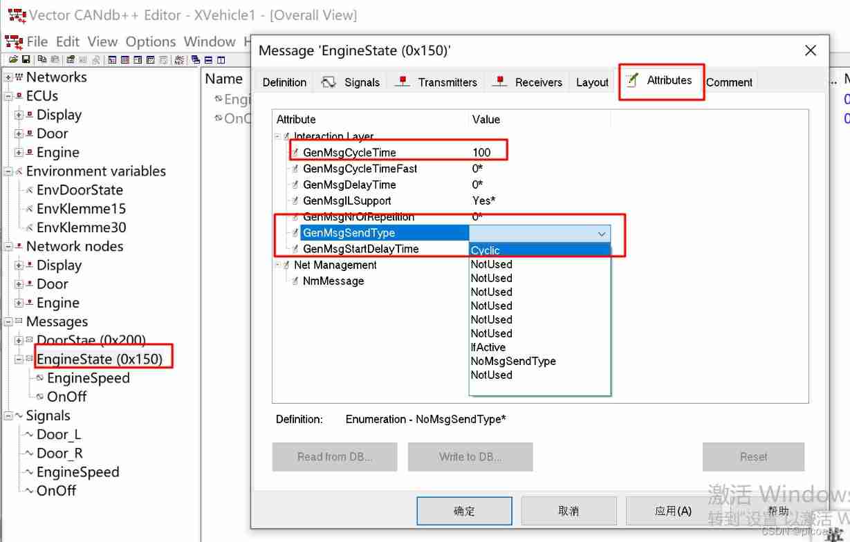
| EngineState | 0x150 | 2 | CAN standard | Engine | 100 | Cyclic | |
| DoorState | 0x200 | 1 | CAN standard | Door | 200 | Cyclic |
To configure Message cycle
The signal ——Signal
Signal( The signal ) It is the smallest unit of bus communication , A signal in the database consists of the following attributes .
- 【 Signal format 】:Name( Signal name ) Length[Bits]( Signal length ) Byte Order( Byte order )Value Type( data type ) Unit( Physical units )
- 【 Value settings 】Init.Value( Initial value ) Factor( weighting )Maximum( Maximum ) Minimum( minimum value )
- 【 Value meaning description 】Value Table( Numerical table )
- 【 Which message is associated 】Messages( message )
- 【 Transceiver node 】Receivers( Receiving node )
- 【 other 】Attributes( General properties ) ·Value Descriptions( Numerical description ) ·Comment( explain )
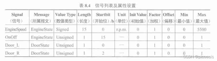
X-Vehicle-1 There is 4 A signal : Engine speed (EngineSpeed)、 Engine status (OnOff)、 Left door switch status (Door_L) And right door switch status (Door_R).
Signal configuration information
Add this... According to the corresponding attribute value 4 A signal :
| Signal | Message | Value Type | Length | Byte Order | Start Bit | Unit | Init Value | Factor | Offset | Min | Max | Value Table |
Engine Speed | Engine State | Singed | 15 | Intel | 0 | r.p.m | 0 | 1 | 0 | 0 | 5500 | - |
| OnOff | Engine State | Unsigned | 1 | Intel | 15 | - | 0 | 1 | 0 | 0 | 1 | |
| Door_L | DoorState | Unsigned | 1 | Intel | 0 | - | 0 | 1 | 0 | 0 | 1 | name vtSig _Door _Status |
Value description :0:close 1:open | ||||||||||||
| Door_R | DoorState | Unsigned | 1 | Intel | 2 | - | 0 | 1 | 0 | 0 | 1 | name vtSig _Door _Status; Value description :0:close 1:open |
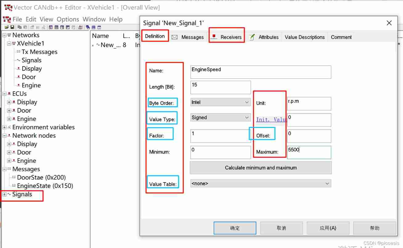
With EngineState As an example, the operation is shown in the following figure :
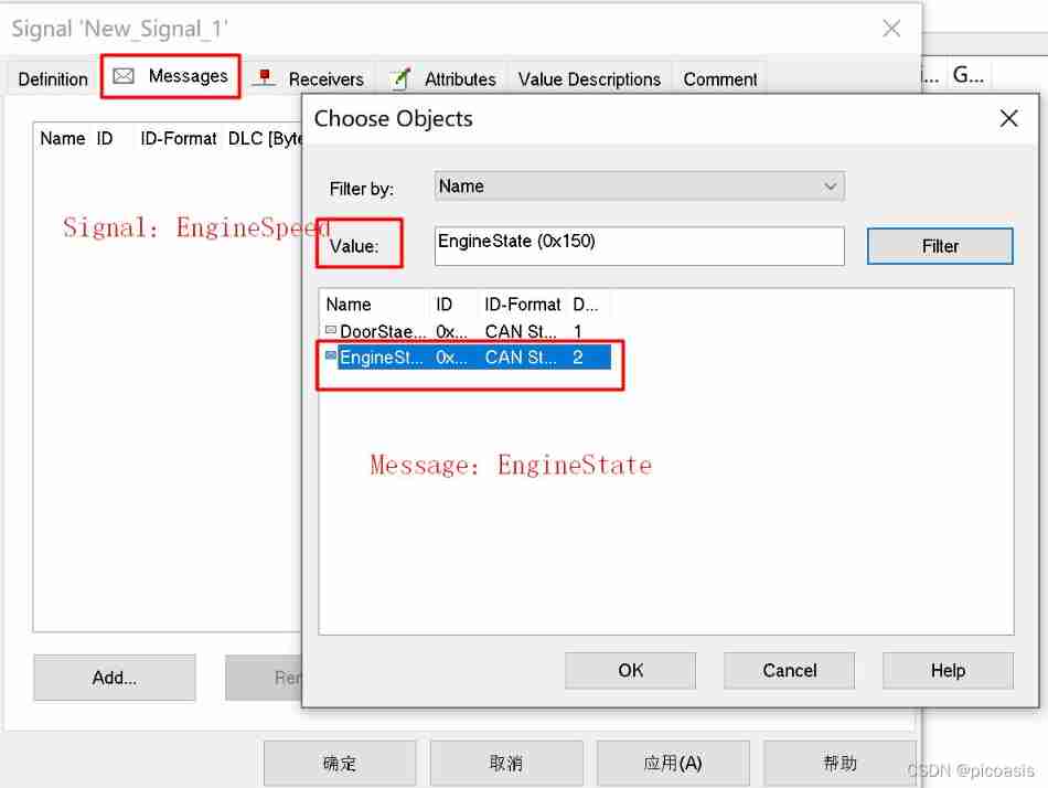
The signal Signal Associated message Message:
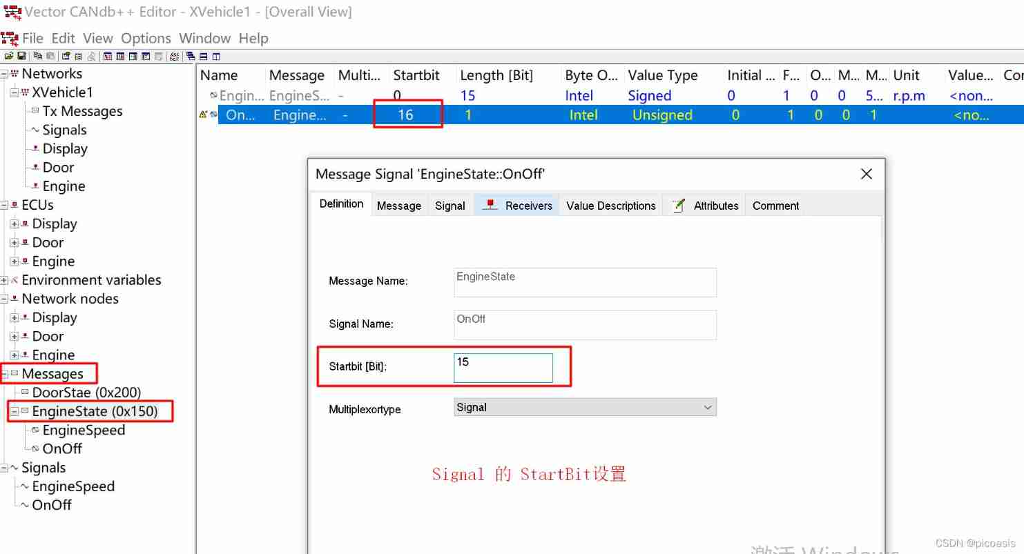
StartBite Setup example :
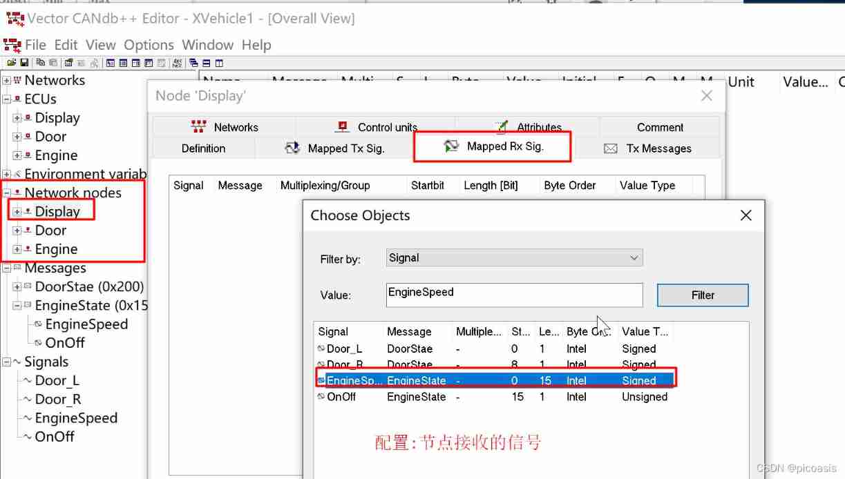
Configure the signal at different nodes Send and receive :
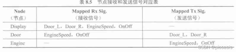 Configuration example of node receiving signal :
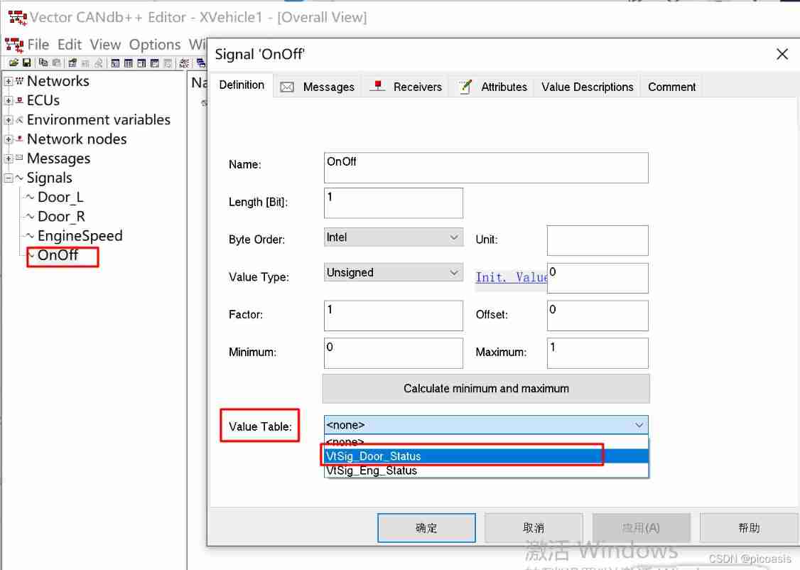
Value Table To configure
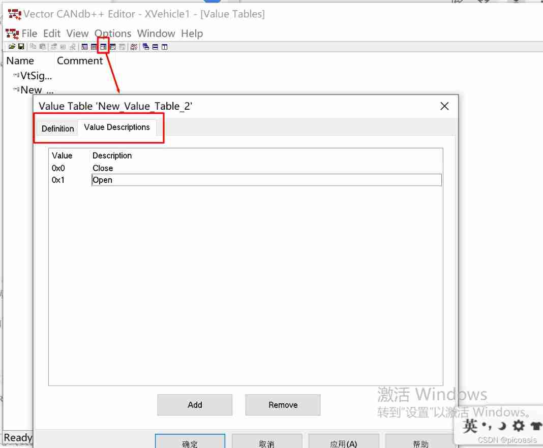
Set the signal Valuetable:
Signal Attribute interpretation :
1. Factor and Offset Defined raw value And physical value The relationship between .
- raw value yes CAN The message is sent to Hexadecimal data on the bus ,
- physical value Is the value of the physical quantity represented by the signal , for example , The speed of the car 、 speed 、 Temperature etc. .
- Init.Value、Minimum and Maximum Are all physical value.
- raw value And physical value And Between the The relationship is :
- physical value=([raw value]×[Factor])+[Offset].
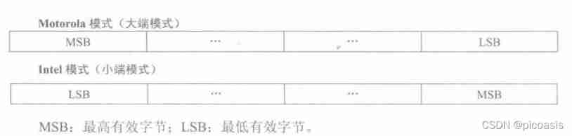
2. Byte Order
Signals in the database Byte Order( Byte order ) It is divided into Motorola and Intel Two data formats ( Also known as big End mode and small end mode ), The byte order of the two formats is as follows .
3. Value Table
Value Table( Numerical table ) It is used to specify the meaning represented by the value of signal or environment variable in writing , for example , The signal created earlier OnOff,0 representative Off state ,1 representative On state .
signal and Environment Variables All have this property .
environment variable Environment Variables
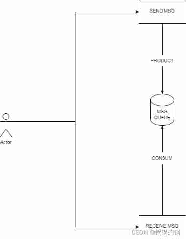
Environment Variable( environment variable ) yes ECU、 Panels and CAPL The media through which programs are connected .
for example , stay CAPL In the program , Specific actions can be triggered by changing or monitoring the value of an environment variable , Again , Environmental change The value of the quantity can also be associated with the control control or display control on the panel .
Compared with system variables , Environment variables are only used in CANdb++ In the definition of . This example uses DBC Templates , Two environment variables will be automatically created EnvKlemmel5 and EnvKlemme30, You can delete it directly if you don't need it .
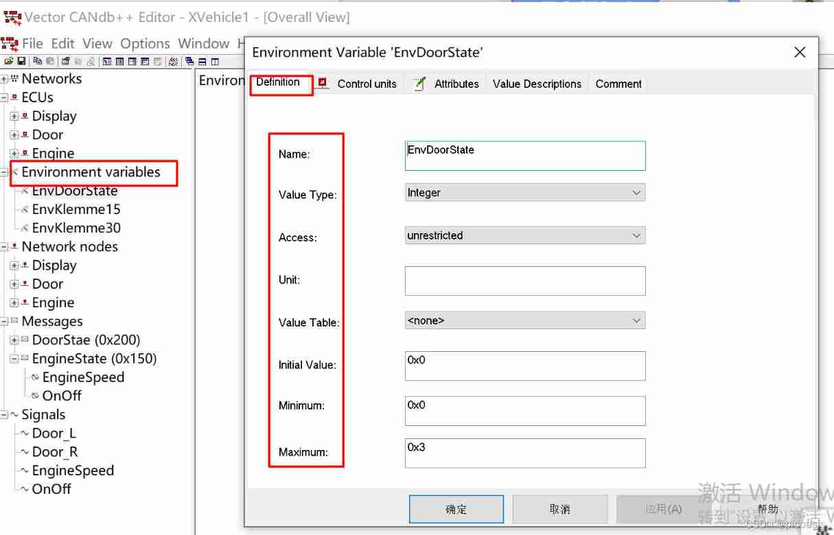
Environment variable configuration
X-Vehicle-1 There is 1 Environment variables EnvDoorState. Configure as shown below
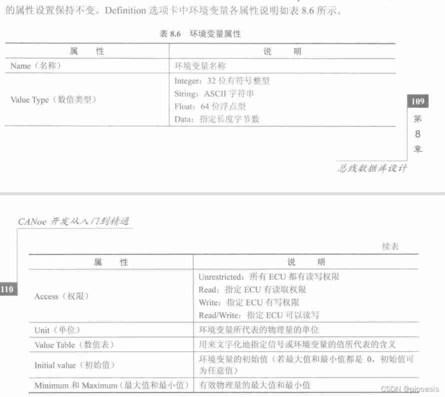
Description of the meaning of environment variable attributes :
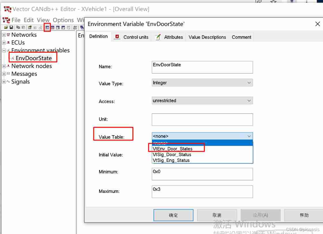
Environment variable ValueTabe To configure
EnvDoorState Of valueTable Configuration values
- Name: VtEnv_Door_Status
- Value Description:
- 0: BothDoorClose:
- 1: LeftDoorOpen:
- 2: RightDoorOpen:
- 3: BothDoorOpen
operation -1: To configure ValueTable

operation -2 Set up EnvDoorState Of ValueTable
Consistency check
If it passes the consistency test , No alarm or error , Then the design of the database is completed .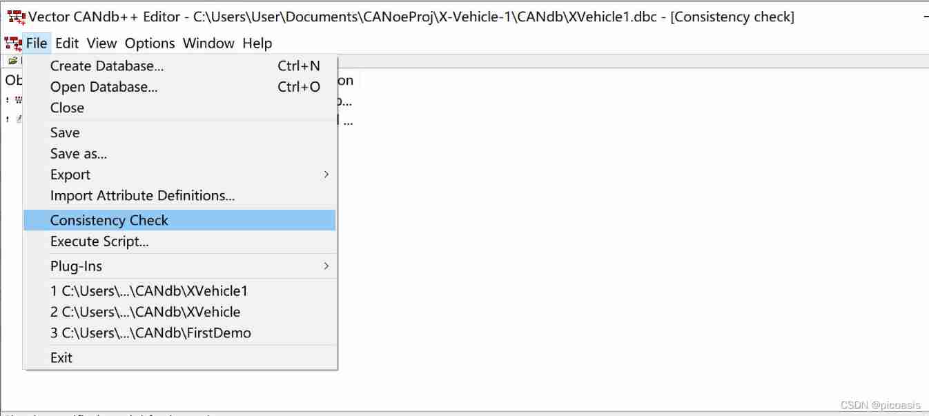
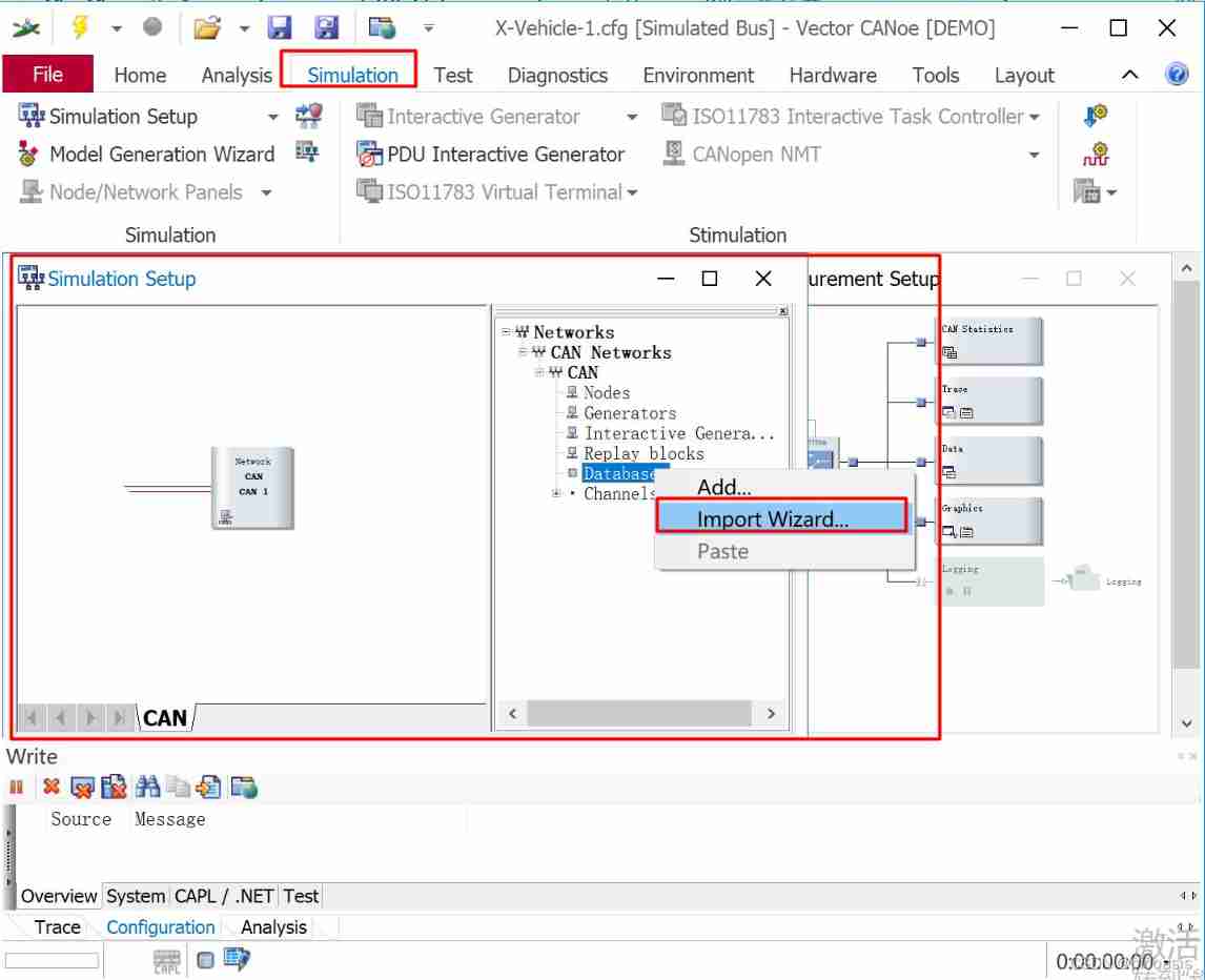
5. Database engineering XVehicle.dbc Import project file
CAN After database creation , You can import it into the created project file . This will be described below XVehicle1 The database imports the previously created X-Vehicle-1 In the project .
stay Simulation Setup In the system view of , Right click Database choice Import Wizard command , In the pop-up Select... In the dialog box XVehicle database , And the nodes Display、Door and Engine Add to Assigned nodes in , Pictured 8.24 Shown .
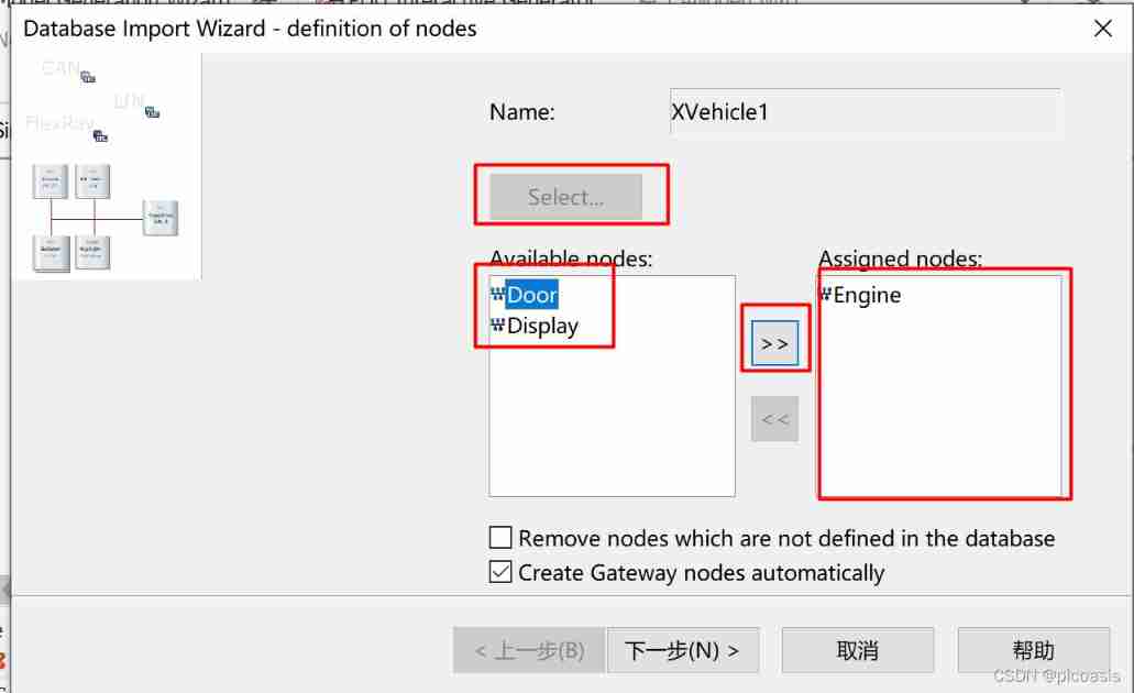
complete X-Vehicle-1 Database design of the project .
END
边栏推荐
- unit testing
- Linked list operation can never change without its roots
- Pod management
- /*The rewriter outputs the contents of the IA array. It is required that the type defined by typedef cannot be used in the outer loop*/
- VI text editor and user rights management, group management and time management
- BGP advanced experiment
- 1. Circular nesting and understanding of lists
- Performance test overview
- Delayed message center design
- First article
猜你喜欢
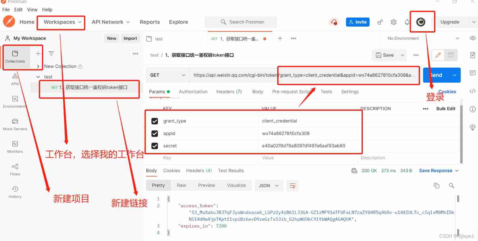
Postman interface test
Personal thoughts on the development of game automation protocol testing tool
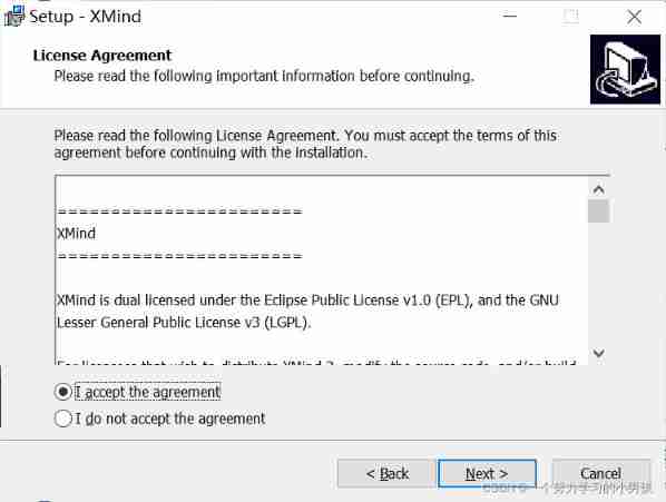
XMIND installation

BGP ---- border gateway routing protocol ----- basic experiment
![[Galaxy Kirin V10] [desktop] can't be started or the screen is black](/img/68/735d80c648f4a8635513894c473860.jpg)
[Galaxy Kirin V10] [desktop] can't be started or the screen is black
![[Galaxy Kirin V10] [server] FTP introduction and common scenario construction](/img/ef/f0f722aaabdc2d98723cad63d520e0.jpg)
[Galaxy Kirin V10] [server] FTP introduction and common scenario construction
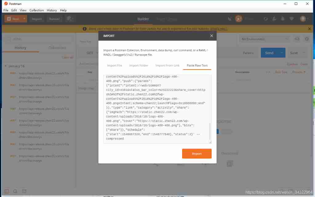
Send a request using paste raw text
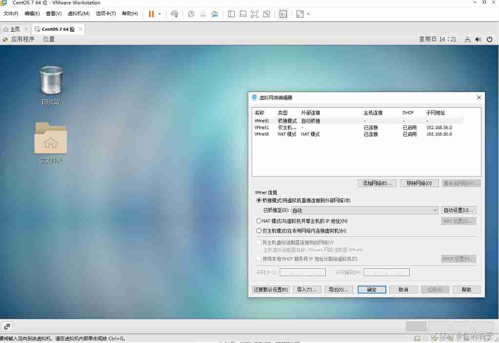
Virtual machine configuration network
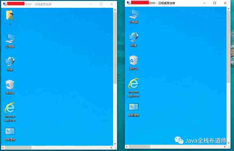
The most detailed teaching -- realize win10 multi-user remote login to intranet machine at the same time -- win10+frp+rdpwrap+ Alibaba cloud server
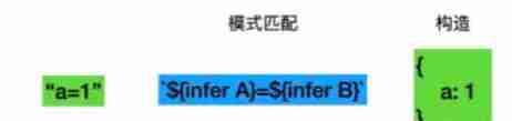
TS type gymnastics: illustrating a complex advanced type
随机推荐
Advanced order of function
DCL statement of MySQL Foundation
51 data analysis post
OSPF summary
Huge number (C language)
Architecture introduction
Collection of practical string functions
Velodyne configuration command
For and while loops
Latex arranges single column table pictures in double column format articles
Occasional pit compiled by idea
Aike AI frontier promotion (2.14)
Jemeter script recording
Rhcsa operation
VLAN part of switching technology
Debug:==42==ERROR: AddressSanitizer: heap-buffer-overflow on address
leetcode842. Split the array into Fibonacci sequences
Add t more space to your computer (no need to add hard disk)
Rhcsa12
Evolution from monomer architecture to microservice architecture