当前位置:网站首页>Basic IO interface technology - microcomputer Chapter 7 Notes
Basic IO interface technology - microcomputer Chapter 7 Notes
2022-07-02 21:36:00 【IOT classmate Huang】
basic I/O Interface technology —— Microcomputer Chapter 7 Notes
List of articles
- basic I/O Interface technology —— Microcomputer Chapter 7 Notes
- Preface
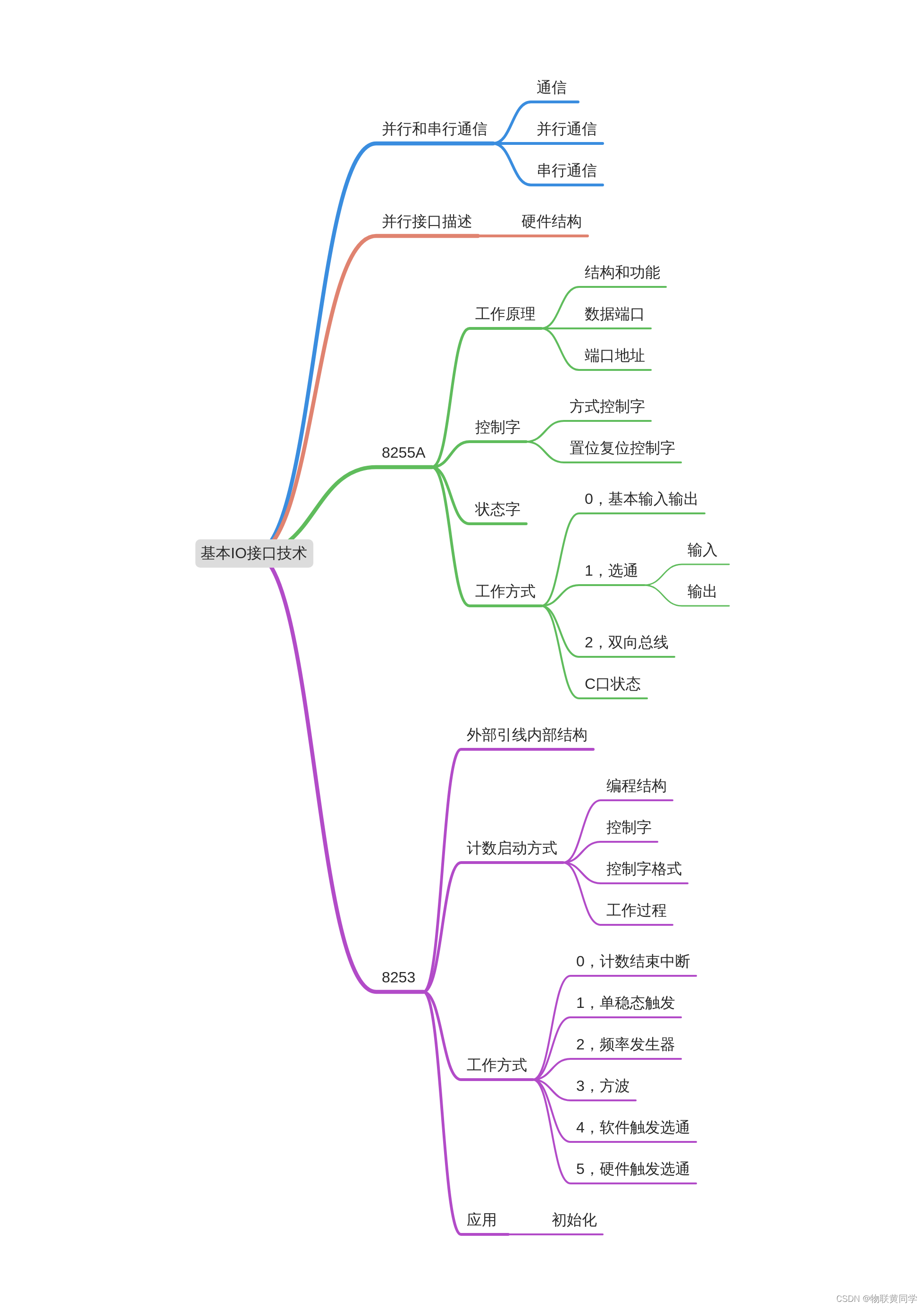
- MindMap
- Parallel communication and serial communication
- Overview of parallel interfaces
- 8255A
- Programmable timing / Counter 8253
- The latter
Preface
Tomorrow's exam , Satcom !
This chapter is mainly about some knowledge points of parallel interface , involves 8255、8253 There are also serial interfaces .
MindMap
Parallel communication and serial communication
signal communication
Refers to computers and peripherals 、 Between computers Information switching .
The basic method
Parallel communication and serial communication .
Parallel communication
Is to put the data to everyone meanwhile stay Multiple parallel transmission lines for transmission .
advantage
Fast transmission speed , Suitable for high data transmission rate 、 Occasions with short transmission distance .
serial communication
Contrary to parallelism , Press Time sequence Transmit on one transmission line in turn .
characteristic
Transmission speed is slow 、 long-range 、 Low cost , Suitable for long distance 、 Medium and low speed communication .
Overview of parallel interfaces
Parallel interface connection CPU And Parallel peripherals , Realize the Parallel communication .
Hardware structure ( A typical )
- Latched or buffered data port .
- And CPU、 Peripheral devices are necessary for data exchange
controlandstateThe signal . - Port decoding circuit .
- Control circuit .
8255A
Pin structure diagram

There are three 8 Bit parallel port , 40 One pin .
working principle
Structure and function
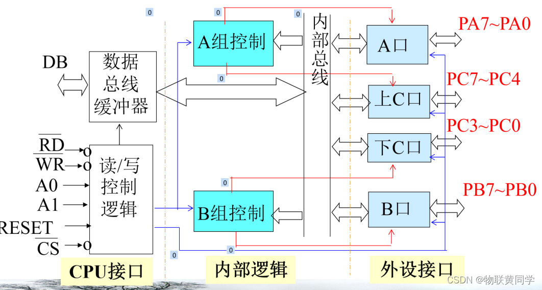
Data port
Yes 3 individual 8 position I/O port (A、B、C),24 root I/O Line and peripheral exchange data or communication ,C The mouth is divided into two 4 Bit mouth .
A、B For oral use 8 Bit data I/O mouth ,C can 8 position , Or two 4 position , It is also often used to cooperate A Mouth and B mouth , As Control signals Output 、 Or as Status signals Input .
Port address


Control word
Mode selection control word
Definition How each port works .
Three ways :
- The way 0—— Basic input and output
- The way 1—— Strobe input and output
- The way 2—— Bidirectional bus I/O The way

Set reset control word
Yes C Port of Perform any set or reset operation .
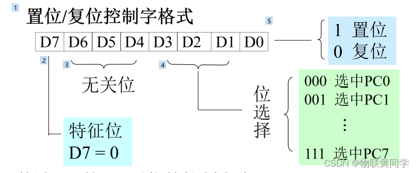
port C Commonly used in control or Answer signal , We can reset and set it , Write through the control port By position / Reset Control word .
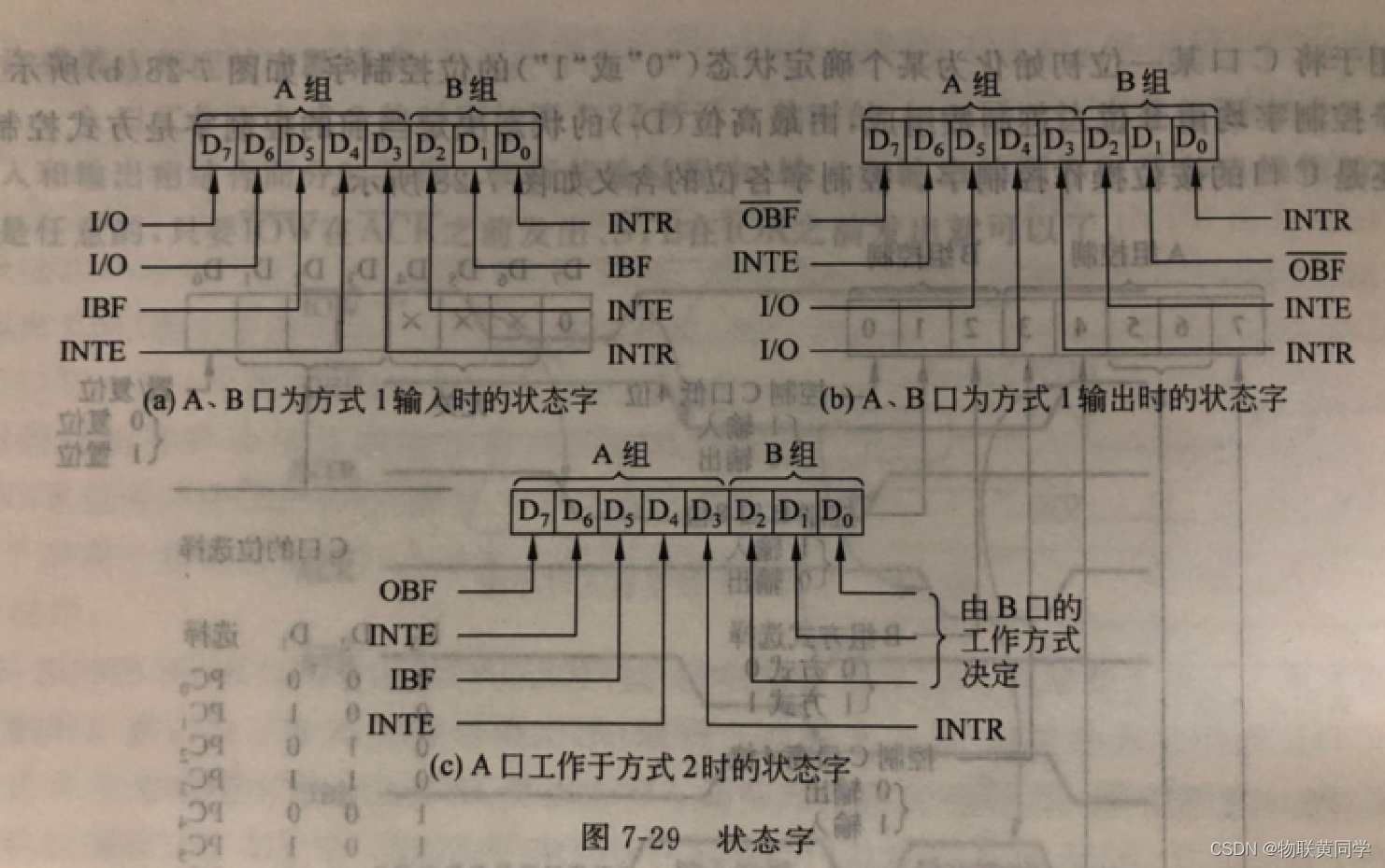
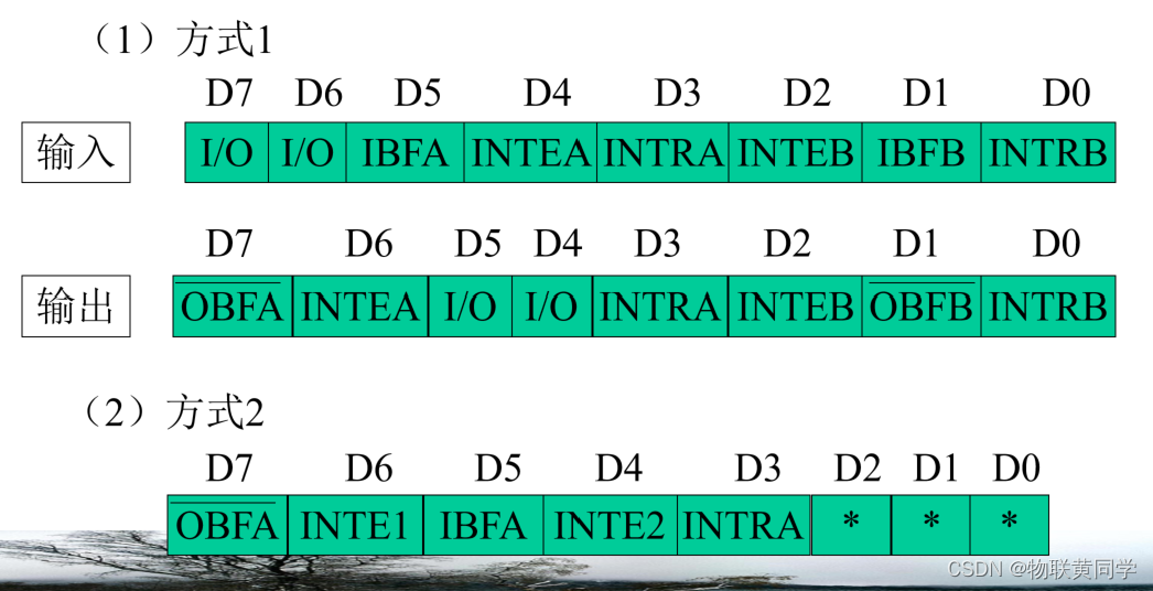
Status word
Operation mode
Mentioned earlier ,8255A There are three ways of working , In ways 1 And way 2 when ,C Mouth for A mouth /B The contact signal of the port , use IN Instructions can be read C The state of the mouth .
The way 0—— Basic input / output mode
It is suitable for simple without answering signals I/O occasion .
The output is latched , Input no latch .
The way 1—— Gate input / Output mode
Input
Both input and output pass Answer signal Realization , This is a A/B Used as a data port ,C The part of is used for Handshake signal line And Interrupt request line .
Input of data port 、 Output can be latched .
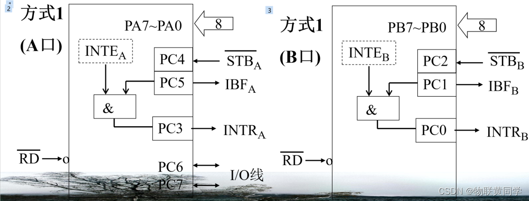
PC35 and PC02 for A Mouth and B State and control line of the port ,PC6~7 Used as a IO Line .
STB- Data strobe input signal , Low level active , Input by peripheral ;
IBF- Input buffer full signal , High active , from 8255A Output status signal , Indicates that the input latch is full , The outward setting indicates that no more data can be sent .
INTEA: Interrupt Enable, Interrupt enable signal , Set the interrupt to allow or mask the interrupt signal .INTE No external leads , By software C Set at a certain position 0 Or place 1 The operation of . Yes A mouth , The interrupt permissive end is PC4, Yes B mouth , yes PC2. Set up 1 Allow the interrupt , Set up 0 Mask interrupt .
INTRA: 8255 towards CPU Application interruption , Highly effective , request CPU interrupt .
INTR For Gao you 3 Conditions : 1) STB For the high , That is, the data has been entered 8255; 2) IBF For the high , namely 8255 Data received ;3) INTE( Interrupt request permission ) For the high , namely 8255 Allow answering in interrupt mode .
INTRA For the high , notice CPU Can take 8255A The number in your mouth .
Output
PC3、PC6 and PC7 do A The response signal of the port ,PC0、PC1 and PC2 do B The response signal of the port . The rest of the PC4 and PC5 It can be used as input or output line .
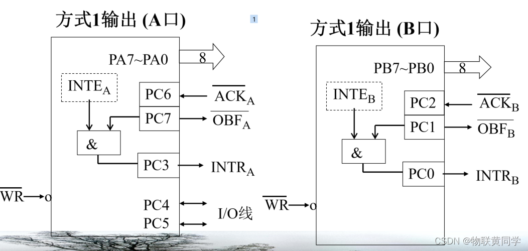
OBF- Output buffer full signal , Output , Low level active . Express CPU Data has been output to the specified port .
ACK- Peripheral response signal , Low level active , Sent by peripherals to 8255A. Express CPU The data sent to the specified port has been accepted by the peripheral .
INTE- Interrupt enable signal .
INTR- Interrupt request signal , High active .
The way 2—— Bidirectional bus mode ( only A mouth )
At this time PA7~PA0 As a bidirectional data bus ,PC3 PC7 Used as a A The communication control signal of the port .PC2PC0 It can be used as B The answer signal line of the port , Or make I/O Line .

INTRA- Interrupt request signal , High active .
OBFA- Output buffer full , Low level active .
ACKA- Peripheral response signal , Low level active .
IBFA- Input buffer full signal , High active .
STBA- Strobe input signal , Low level active .
C Mouth status word
In ways 1 and 2 when ,C The interface generates contact signals with peripherals , Now read C The content of the mouth , Check or test the status of peripherals .
Lai Duan 8255 The compilation of
MOV DX, 1023H           ; set control port address
MOV AL, 1001X000B       ; set function control word
OUT DX, AL
MOV AL, 0               ; line light port PC0, set low
OUT DX, AL

MOV DX, 1021H           ; port B address
MOV AL, 80H             ; pb7
OUT DX, AL              ; open control

A:
MOV DX, 1020H           ; port A address
IN AL, DX               ; get data
CMP AL, 0               ; if PA0~PA7 have one is hight, it impress have abnormal
JZ A                    ; keep monitor

MOV CX, 3               ; set loop times
MOV DX, 1022H           ; port C address

B:
MOV AL, 1
OUT DX, AL              ; alarm lamp light on
CALL DELAY
MOV AL, 0
OUT DX, AL              ; alarm lamp light off
CALL DELAY
LOOP B
JMP A                   ; keep monitor
Programmable timing / Counter 8253
8253 It's a kind of Hardware timing / Counter chip
One 、 External lead level internal structure
3 individual 16 Bit timing / Counter ( passageway )
24 Pin dual in line
Maximum counting frequency 2.6MHz
TTL Level compatible
Single power supply +5V Power supply
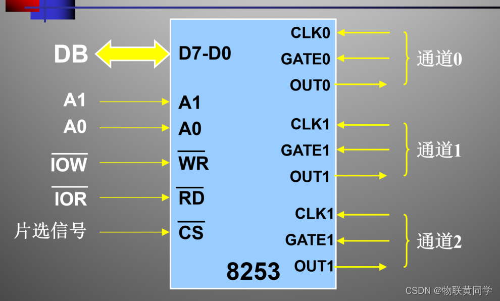
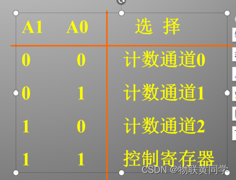
Channel selection

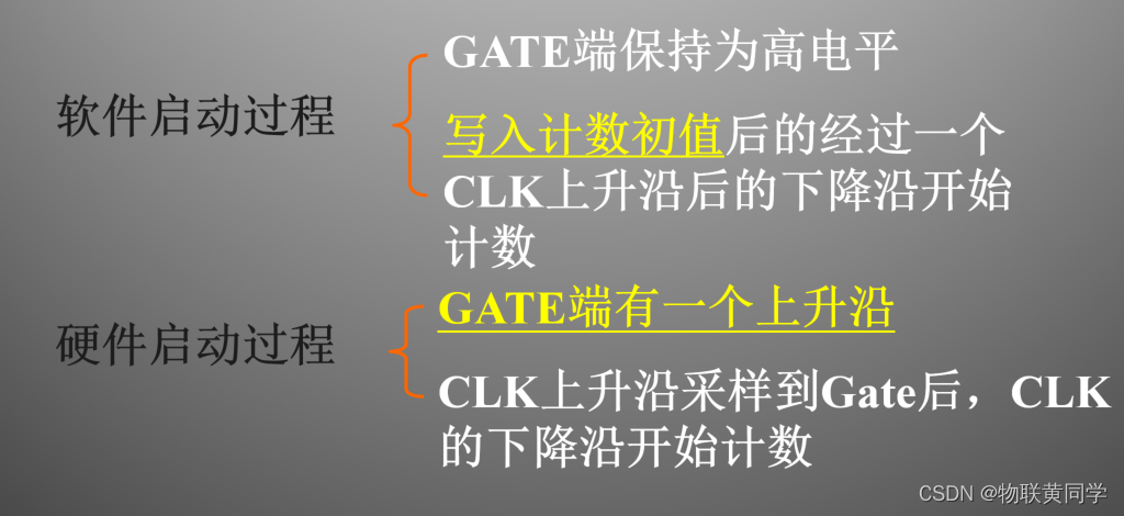
Two 、 Count start mode
branch Program instructions start ( Soft start ) and The external circuit signal starts ( Hardware boot ) Two processes .
Programming structure

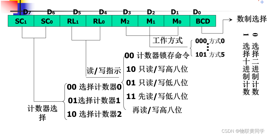
Control word

8253 Control word format
working process
- Set up 8253 How it works
- Set count initial value to initial value register
- first CLK The falling edge signal causes the contents of the initial value register to be placed in the count register
- Every one in the future CLK The signal , Count register minus 1
- Reduced to 0 when ,OUT The terminal outputs a special waveform signal
notes : The above counting process is also subject to GATE Signal control
3、 ... and 、 Operation mode
Control word D1~D3 In fact, that is Choice of working mode , There are the following 6 Ways of working :
The way 0—— Interrupt count end
The way 1—— Repeatable monostable trigger
The way 2—— Frequency generator
The way 3—— Square wave generator
The way 4—— Software triggered strobe
The way 5—— Hardware triggered strobe
The way 0 Interrupt count end
Software startup , Do not automatically repeat the count . After loading the control word OUT The terminal becomes low , End of count OUT Output high level .
During counting ,GATE The terminal shall remain high .GATE The signal goes low , Then pause counting , until GATE recovery .OUT The end output is about (N+1)TCLK Negative pulse of width . During the counting process, the initial value can be modified at any time to restart the counting .
The way 1 Monostable trigger
Hardware boot , Do not automatically repeat the count . After loading the control word OUT The terminal becomes high . Counting starts OUT The terminal becomes low , The count goes up again after the end .
Gate signals GATE The jump trigger count of the terminal , Repeatable trigger . If next time GATE The rising edge arrives ahead of time , be OUT The end negative pulse broadening is the sum of two counting processes . Writing a new initial value during counting does not affect this count .
The way 2 Frequency generator
soft 、 Hardware boot , Automatic repeat count . After loading the control word OUT The terminal becomes high , Count to the last CLK when OUT Output negative pulse , And repeat this process continuously .
GATE Control signal for counting :GATE Lower the count and stop , The next one when it gets higher CLK Falling edge , Recount from initial value .
At the end of each counting cycle ( Reduced to 1 when ),OUT Output a TCLK Negative pulse of width .
The counting process is automatically repeated .
Modifying the initial value in the counting process does not affect the counting process of this round .
The way 3 Square wave generator
soft 、 Hardware boot , Automatic repeat count . After loading the control word OUT The terminal becomes high , then OUT Continuous output symmetrical square wave : front N/2 or (N+1)/2 individual CLK,OUT For the high , after N/2 or (N-1)/2 individual CLK, OUT For low .
OUT Output square wave , The first half cycle is high , The second half cycle is low .
Modifying the initial value during counting does not affect the counting process of this half cycle .
GATE It can be used as a control signal for counting :GATE Lower the count and stop , The next one when it gets higher CLK Falling edge , Recount from initial value .
The way 4 Software triggered strobe
Software startup , Do not automatically repeat the count . After loading the control word, the output terminal becomes high , After counting, output a CLK Negative pulse of width .
During counting ,GATE The terminal shall remain high .
Every time the initial value is written , Count a cycle , Then stop counting .
At the end of each counting cycle ( Reduced to 0 when ),OUT Output a TCLK Negative pulse of width .
Modifying the initial value in the counting process does not affect the counting process of this round .
The way 5 Hardware triggered strobe
Hardware boot , Do not automatically repeat the count .OUT Terminal waveform and mode 4 identical .
When writing the initial value ,GATE The terminal should be kept low .
GATE Every time a positive pulse appears , Count a cycle , Then stop counting .
At the end of each counting cycle ( Reduced to 0 when ),OUT Output a TCLK Negative pulse of width .
Modifying the initial value in the counting process does not affect the counting process of this round .
Four 、8253 Application
Three parts : Connect the system 、 Set the way it works 、 Set initial value of count . The last two are programming .
Initialize program flow

CNT0:
MOV DX, 0123H       ; set control port address
MOV AL, 34H         ; set word funtion is 2
OUT DX, AL
MOV DX, 01020H      ; counting channel 0
MOV AX, 20000
OUT DX, AL          ; clock frequency
MOV AL, AH
OUT DX, AL
I don't understand this either , Look around
MOV DX, 3E3H        ; set control port address
MOV AL, 00110110B   ; chanel 0, function 3
OUT DX, AL
MOV DX, 3E0H        ; chanel 0 port address
MOV AX, 20000       ; 2MHz
OUT DX, AL
MOV AL, AH
OUT DX, AL

XOR AL, AL
MOV DX, 3E5H
OUT DX, AL          ; set 0 let cp goto
MOV DX, 3E4H        ; trisate gate

NEXT:
IN AL, DX
AND AL, 01H
JZ NEXT

MOV DX, 3E5H
MOV AL, 2
OUT DX, AL

GOON:
MOV AH, 1
INT 16H
JZ GOON
XOR AL, AL
OUT DX, AL
MOV AH, 4C
INT 21H
The latter
Other , Serial interfaces and parallel asynchrony are not the focus , So stop writing .
边栏推荐
- 如何防止你的 jar 被反编译?
- Research Report on minimally invasive medical robot industry - market status analysis and development prospect prediction
- Research Report on plastic antioxidant industry - market status analysis and development prospect forecast
- Adding data to the head or tail of the rar file can still decompress normally
- China microporous membrane filtration market trend report, technological innovation and market forecast
- MySQL learning notes (Advanced)
- treevalue——Master Nested Data Like Tensor
- [shutter] the shutter plug-in is used in the shutter project (shutter plug-in management platform | search shutter plug-in | install shutter plug-in | use shutter plug-in)
- [use of pointer and pointer and array]
- Research Report on crude oil tanker industry - market status analysis and development prospect forecast
猜你喜欢
7. Build native development environment
![[shutter] statefulwidget component (image component | textfield component)](/img/4b/8e54607939989f994303ce5d922331.gif)
[shutter] statefulwidget component (image component | textfield component)

Report on investment development and strategic recommendations of China's vibration isolator market, 2022-2027

Baidu sued a company called "Ciba screen"
MySQL learning record (3)
![[shutter] statefulwidget component (floatingactionbutton component | refreshindicator component)](/img/17/b5889ec263687aeacf19214785ea8a.jpg)
[shutter] statefulwidget component (floatingactionbutton component | refreshindicator component)

26 FPS video super-resolution model DAP! Output 720p Video Online
![[CV] Wu Enda machine learning course notes | Chapter 12](/img/c8/9127683b6c101db963edf752ffda86.jpg)
[CV] Wu Enda machine learning course notes | Chapter 12
5 environment construction spark on yarn

Investment strategy analysis of China's electronic information manufacturing industry and forecast report on the demand outlook of the 14th five year plan 2022-2028 Edition
随机推荐
Research Report on ranking analysis and investment strategic planning of RFID market competitiveness of China's industrial manufacturing 2022-2028 Edition
Construction and maintenance of business website [1]
Three chess games
如何防止你的 jar 被反编译?
Research Report on market supply and demand and strategy of China's atomic spectrometer industry
Construction and maintenance of business websites [7]
qwb2018_ core kernel_ rop
26 FPS video super-resolution model DAP! Output 720p Video Online
BitSet complement
Research Report on the overall scale, major manufacturers, major regions, products and application segmentation of signal distributors in the global market in 2022
[shutter] statefulwidget component (create statefulwidget component | materialapp component | scaffold component)
China's Micro SD market trend report, technology dynamic innovation and market forecast
MySQL learning record (9)
1007 maximum subsequence sum (25 points) "PTA class a exercise"
基本IO接口技术——微机第七章笔记
MySQL learning notes (Advanced)
A river of spring water flows eastward
Basic knowledge of tree and binary tree (detailed illustration)
Construction and maintenance of business website [3]
[hands on deep learning]02 softmax regression