当前位置:网站首页>[quick start of Digital IC Verification] 13. SystemVerilog interface and program learning
[quick start of Digital IC Verification] 13. SystemVerilog interface and program learning
2022-07-07 08:13:00 【luoganttcc】
Reading guide : The author has the honor to be a pioneer in the field of electronic information in China “ University of electronic technology ” During postgraduate study , Touch the cutting edge Numbers IC Verification knowledge , I heard something like Huawei Hisilicon 、 Tsinghua purple light 、 MediaTek technology And other top IC related enterprises in the industry , Pairs of numbers IC Verify some knowledge accumulation and learning experience . Want to get started for help IC Verified friends , After one or two thoughts , This column is specially opened , In order to spend the shortest time , Take the least detours , Most learned IC Verify technical knowledge .
List of articles
- One 、 Description of content
- Two 、 Verify the connection between the platform and the design to be tested
- 2.1、Verilog How to connect
- 2.2、Verilog How to connect
- 2.3、SystemVerilog Interface
- 2.4、Clocking
- 2.4.1、Clocking: Timing of excitation (1/8)( understand , Is not important )
- 2.4.2、Clocking: Timing of excitation (2/8)
- 2.4.3、Clocking: Timing of excitation (3/8)( understand , Is not important )
- 2.4.4、Clocking Skew(4/8)(skew understand , Is not important )( Learn grammar , stay interface In the definition of )
- 2.4.5、Clocking Blocks(5/8)( important , Learn the usage )
- 2.4.6、Clocking Block: Signal synchronization (6/8)
- 2.4.7、Clocking Block: Signal synchronization operation (7/8)
- 2.4.7、Clocking summary (8/8)
- 2.5、Program Block( dried food )
- 2.6、 Verification platform - Top level documents top
- 3、 ... and 、 Practice
One 、 Description of content
interface
- 1、 Verification platform (TestBench) And the design to be tested (DUT) The connection of
- 2、Verilog Port connection mode and disadvantages
- 3、SystemVerilog interface
- 5、SystemVerilog clocking block
program
- SystemVerilog program block
Simulation ( Understanding can )
- 1、 Simulation time ( understand )
- We do EDA verification , It is more about logical function verification , Don't pay too much attention to timing (setup、hold Wait , Back end STA Will care more ).
- 2、 Simulation time domain :timing region( understand )
Two 、 Verify the connection between the platform and the design to be tested
2.1、Verilog How to connect
- Verilog module ports
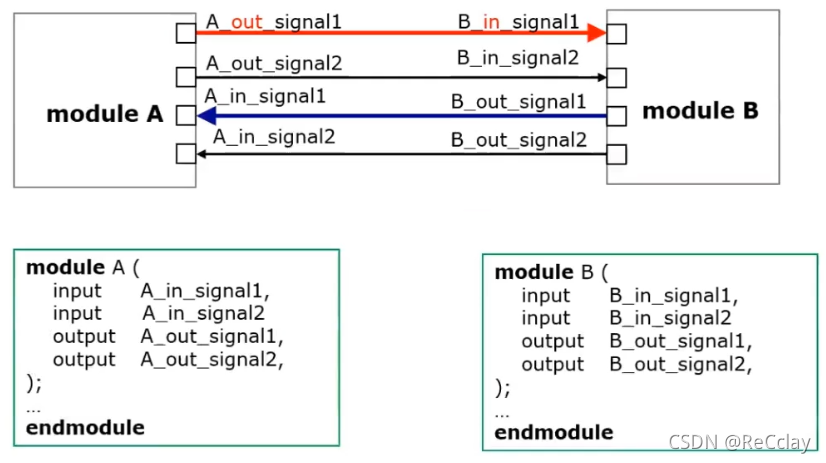
- Verilog Language uses port names to connect various functional modules

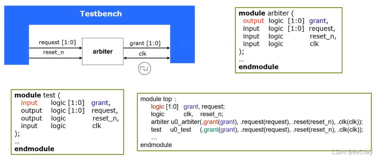
- Arbiter : For something , Resources are limited , If more than one person applies , Then you need an arbiter to decide who can use it !
- logic Can be regarded as wire and reg The combination of
Implicit .* Port connection ( The actual use is still It is not recommended to use )
- SystemVerilog
.*Can automatically match with The same name Network and ports ( Poor flexibility ) - Auto matching names must have the same port bit width
- The connected port type must be compatible
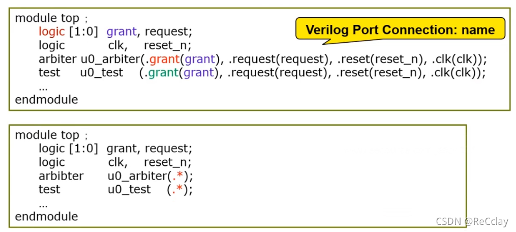
Implicit .name Connect ( The actual use is still It is not recommended to use )
- .name Is a simplified form of connection using port names
- .name The port name and bit width must be consistent
- .name Simplify the connection between instance modules

2.2、Verilog How to connect
Verilog The connection mode of module port of is relatively cumbersome !Why?( somewhat reluctantly , Simply for the following introduction SV)
For example, send a signal request It is amended as follows request1:
- You need to modify the port list of all modules
- You need to modify the list of all ports of the connection module
- You need to modify the port names of all module instantiations
- You need to modify the module port names of all hierarchical ports
If you forget to change all port names , There will be compilation errors .

SoC(System on Chip ) In large-scale design Verilog The port connection mode of is more complicated !
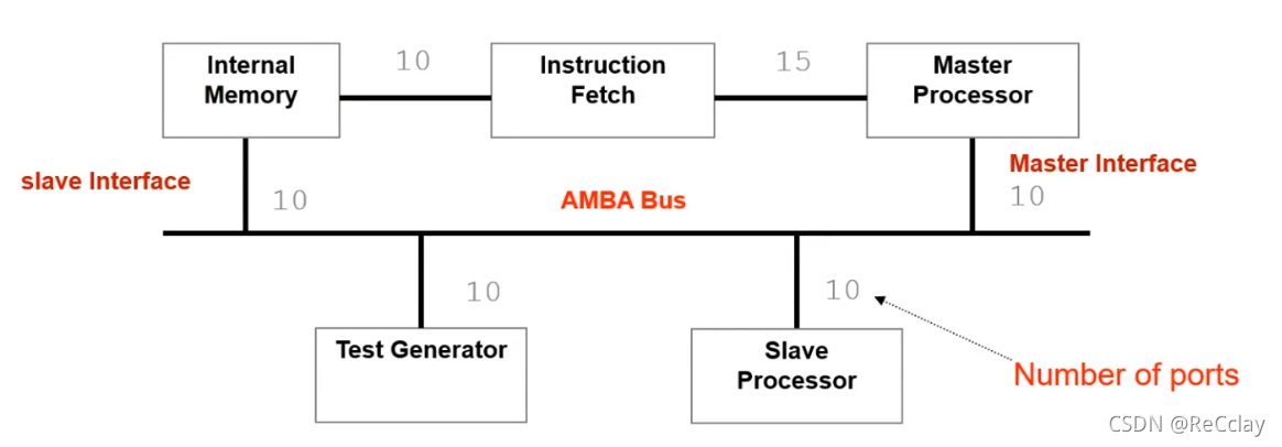
You need to declare the corresponding port in multiple modules
The communication protocol interface is used in multiple modules
Mismatched declarations can lead to compilation errors
After modifying the port name in the design document, you need to modify all modules
SystemVerilog Introduce new port types :interface.
notes :interface More for DUT and TB The connection of !
2.3、SystemVerilog Interface
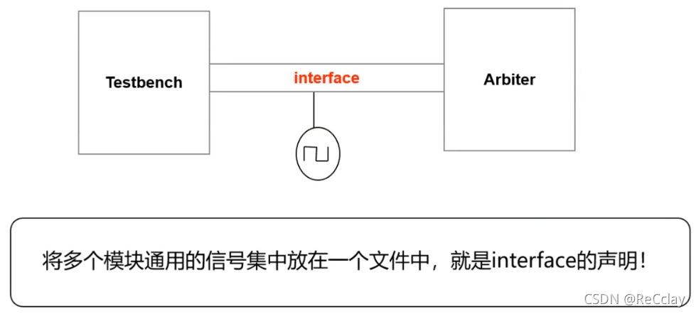
2.3.1、SystemVerilog Interface Brief introduction
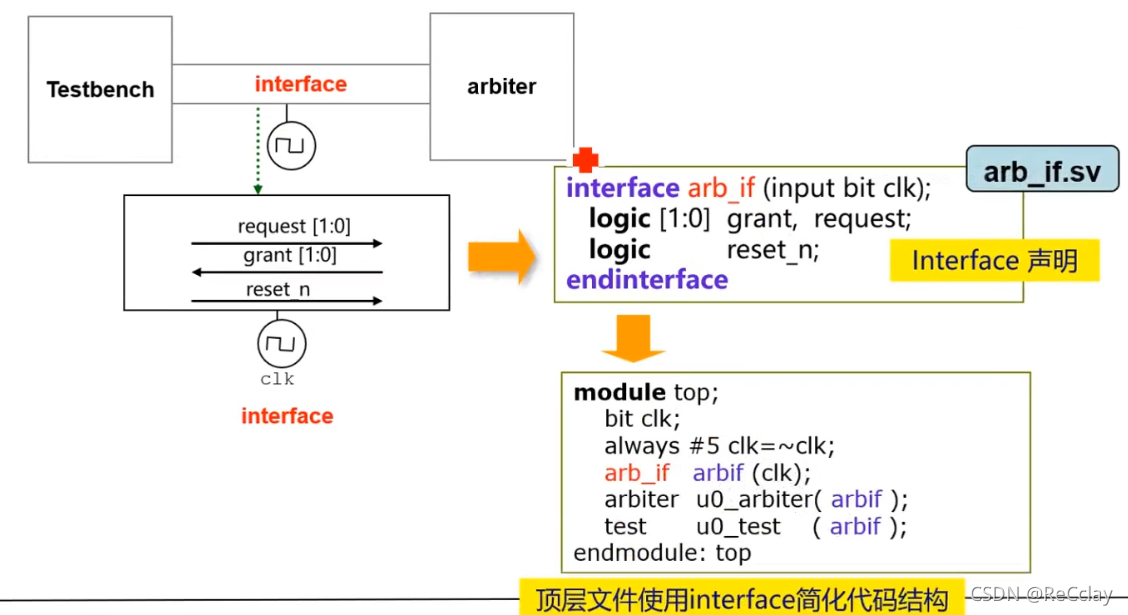
- interface There are many in Verilog Type of signal , It's a Independent port type
- interface It could be a A separate document
2.3.2、 utilize interface Simplify module connections
2.3.3、 How to use interface Medium signal ?
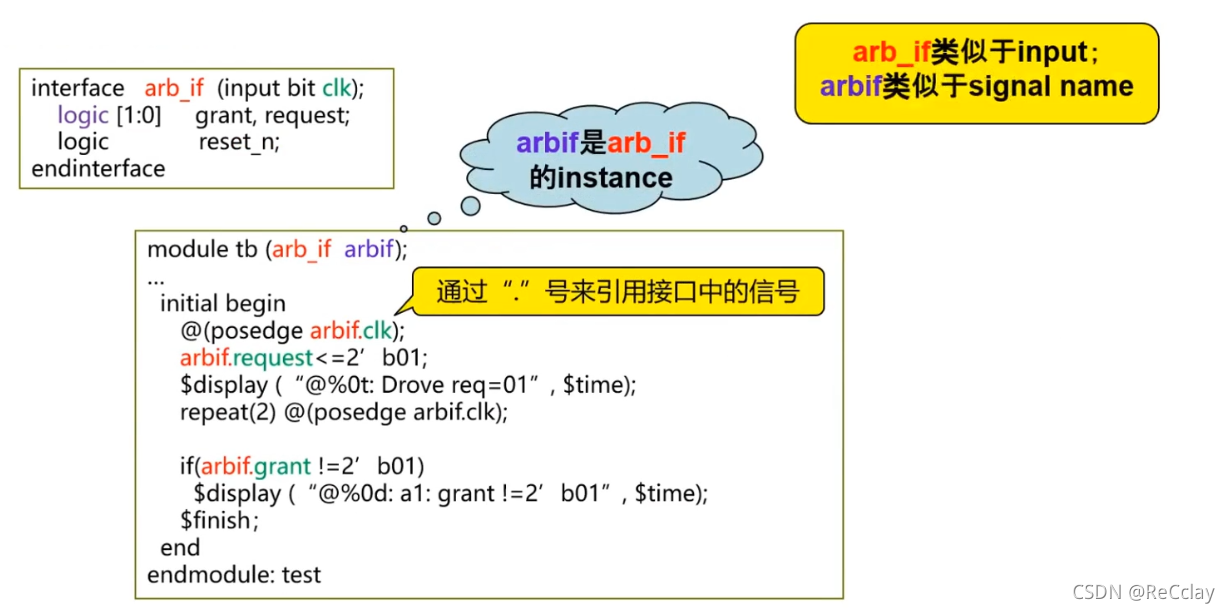
endmodule:testJust for people who read the code , It's equivalent to annotation !- In itself interface The defined signal is non directional , It's a two-way signal !
2.3.4、 Connection between interface and port
- Interfaces reference signals by name
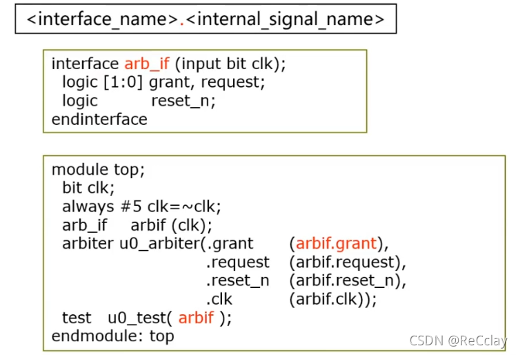
- Above
arbiterandtestIs equivalent !
2.3.5、interface modport
- module port Abbreviation
- modport Provide different perspectives for signals inside the interface (DUT,Test Program)
- One interface Any number of modport
- modport Just declare the port direction of the signal connecting the module :
input、outputandinout(inout Rarely used !)
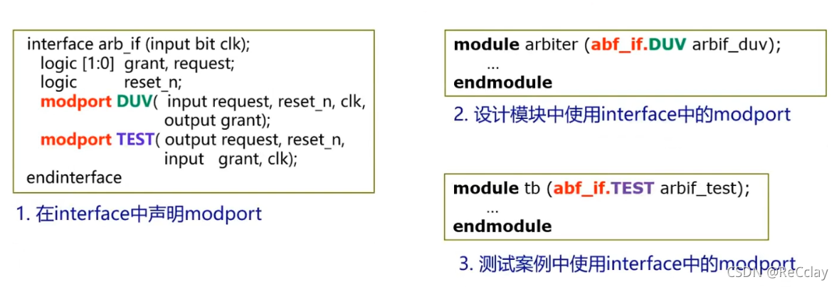
- stay interface At the time of the statement in , The bit width does not need to be specified, just the direction !
2.3.6、SystemVerilog interface Summary
interface The function of
- A set of signals / Wire network
- A separate document
- stay interface Define the communication protocol ( Rarely used )
- stay interface Protocol check and verification functions are defined in :task、function、assertion( Rarely used )
modport Can define interface Different perspectives of (DUT,Test Porgram)
- input
- output
interface Cannot contain the hierarchy of design
- interface It cannot contain module Examples of modules
interface Can be used as a design port , It has comprehensive characteristics ( It is more useful in Engineering Verilog comprehensive , Of course, now integrated tools are slowly supporting SV)
interface It can include multiple modport
2.4、Clocking
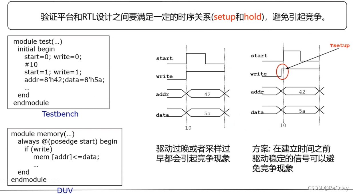
2.4.1、Clocking: Timing of excitation (1/8)( understand , Is not important )
- Not much use , Because we do more logical function verification , Don't pay too much attention to timing !
- Timing is related to the process of using specific device information , These delay information can be reflected in the synthesis process , Only after getting the net list will the time order , To do it STA. stay RTL Stage does not exist STA.
2.4.2、Clocking: Timing of excitation (2/8)
- SystemVerilog Use in clocking Module control Synchronous signal
- stay interface In the definition of clocking modular , take The signal is synchronized to a specific clock
- Clocking All signals in the module are Synchronous drive or sampling , It can ensure that the verification platform can be in correct Time to interact with design
- Clocking The main modules are Used in the verification platform , Can not be used as RTL Design
- One interface Can contain more than one clocking modular
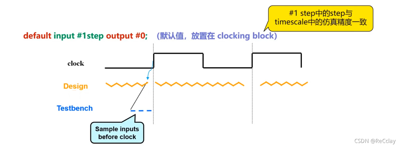
2.4.3、Clocking: Timing of excitation (3/8)( understand , Is not important )
- When using interface and clocking When the module is simulated :
- from DUT Of output to TestBench The input of Yes 1 A delay
- Need to be in Testbench Add a “ Virtual synchronizer ”
- from Testbench Of output to DUT The input of There is no delay
- from DUT Of output to TestBench The input of Yes 1 A delay
2.4.4、Clocking Skew(4/8)(skew understand , Is not important )( Learn grammar , stay interface In the definition of )
- Definition input and output skew, Control timing
- input skew Represents the skew time unit of the sampled signal at the effective edge of the clock
- output skew Represents the skew time unit of the drive signal at the effective edge of the clock
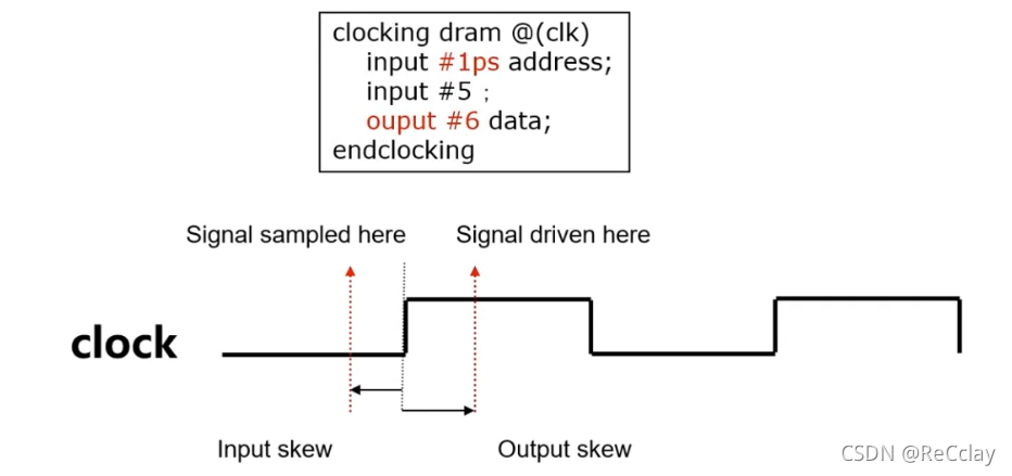
- The code above simulates a D Register output of trigger , Ensure that the signal is synchronized , Ensure that the excitation is in the same clock domain .
2.4.5、Clocking Blocks(5/8)( important , Learn the usage )
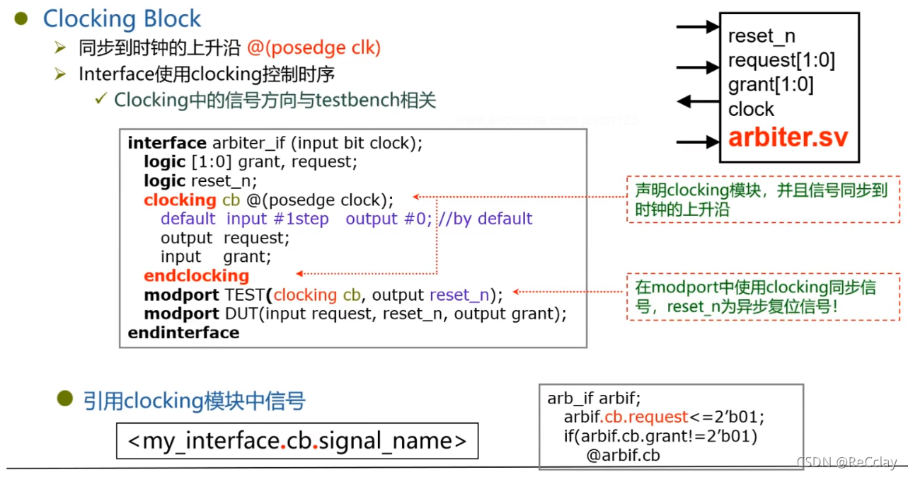
- TEST Medium request It's on the top edge of the clock !( The signal is synchronized to the rising edge of the clock )
- TEST Medium grant It is to collect on the top edge of the clock , It is equivalent to a beat in the register , Delay a shot !
- clk Sync , It is equivalent to a beat in the register , Synchronous clock domain !
@arbif.cbWait for the top edge of the next clock cycle , Equivalent to@(posedge clk)- clock Itself can be replaced by other methods , It is not necessary to have , For example, the writing method in the lower right corner of the above figure can also be written as follows
@(posedge clk)
arb.TEST.request <= 2'b01;
- 1
- 2
- Usually, in actual use, we use the above alternative method more , Remember not to Write code to show off your skills !
- clocking In fact, the function does not bring great benefits !
- Remember that
clockingandmodportyes Optional Of ! Just know the knowledge points , There are other equivalent alternatives
2.4.6、Clocking Block: Signal synchronization (6/8)
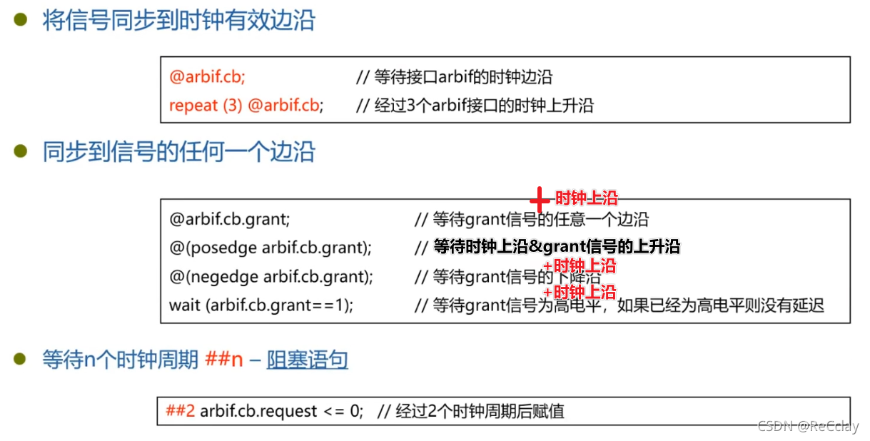
@arbif.cbEquivalent to@(posedge clk)@Waiting for a signal change ( Use up and downposedgeandnegedgedistinguish ),waitWaiting is a level##2wait for 2 individual Clock cycle Equivalent torepeat(n) @arbif.cb
2.4.7、Clocking Block: Signal synchronization operation (7/8)
- Sequential logic uses non blocking
- Combinatorial logic uses blocking
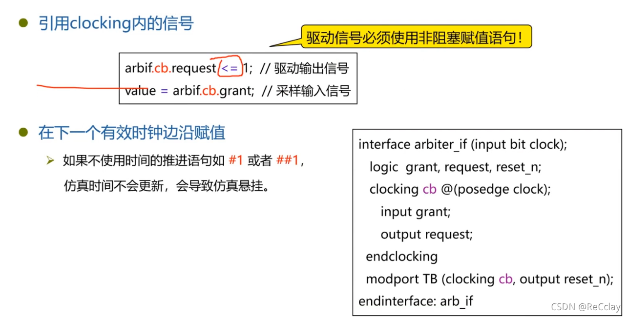
2.4.7、Clocking summary (8/8)
interface Medium clocking For platform verification only , Cannot be used for RTL Design
Clocking The benefits of
- Explicitly indicate the synchronization clock domain
- Verify that the platform drive signal meets the actual requirements , Ensure synchronous behavior
Clocking The function of
- Interface Sure Contains multiple clocking modular
- One clocking modular only one clock
- Clocking The direction of the signal in the module And testbench of
2.5、Program Block( dried food )
2.5.1、Program Block(1/3)
- Program Statement block execution verifies platform code
- Program Statement blocks are similar to module Sentence block , It can contain variables and others module Instantiation of modules
- Program Cannot contain hierarchical institutions , Like other module or interface Example
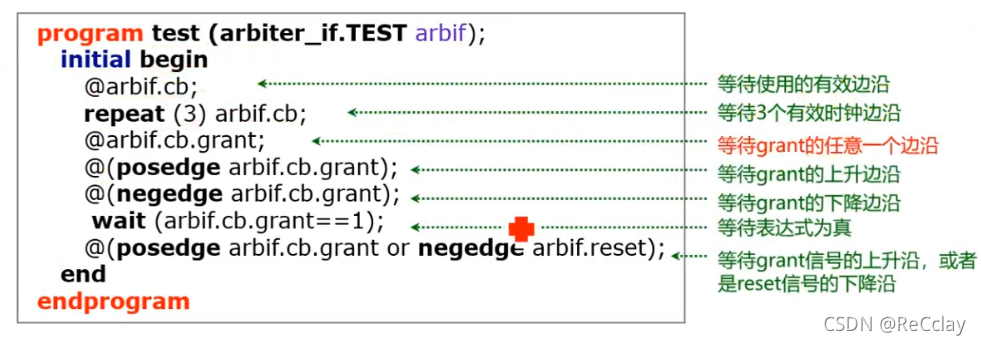
2.5.2、Program Block(2/3)
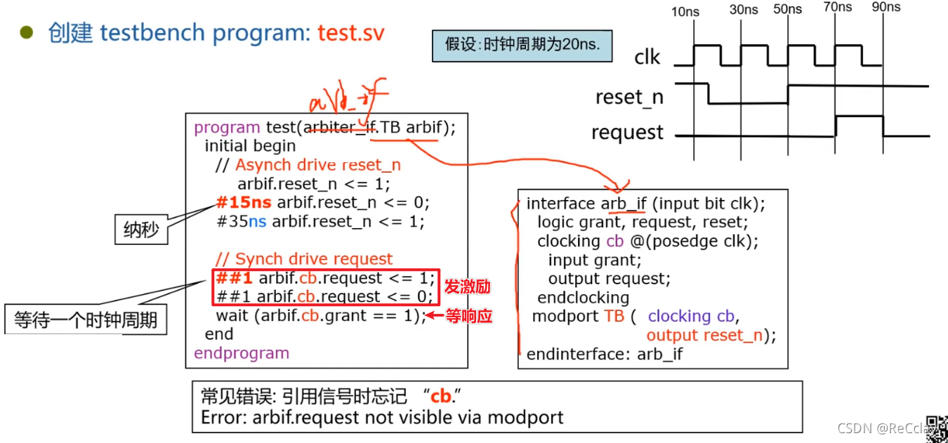
#You can add time units by yourself ;##xExpress x individual cb Clock cycle , and cb With posedge.
2.5.3、Program Block(3/3)
Program benefits
- Separate the verification platform from the design to be tested
- Program Used to execute test cases (testcase)【 The interview is important 】
- Program Used to encapsulate data related to test cases 【 The interview is important 】
Program function
- It can be instantiated in any hierarchy
- Usually in the top-level file
- Can be like module The use of interface Connect to port
- No, module hierarchy , Only class Hierarchical structure
- There can be initial、task and function Code , But it can't exist always sentence
- When Program Medium initial At the end of the statement , Implicit execution
$finish
- It can be instantiated in any hierarchy
notes : For simulation ,
programFollowmoduleequally , The only difference may be to write one less$finish. Or that sentence , This is also Optional Of ! Not necessarily used in Engineering , More for the integrity of the knowledge system ! howeverinterfaceIt is still very important in Engineering , Pay special attention to .
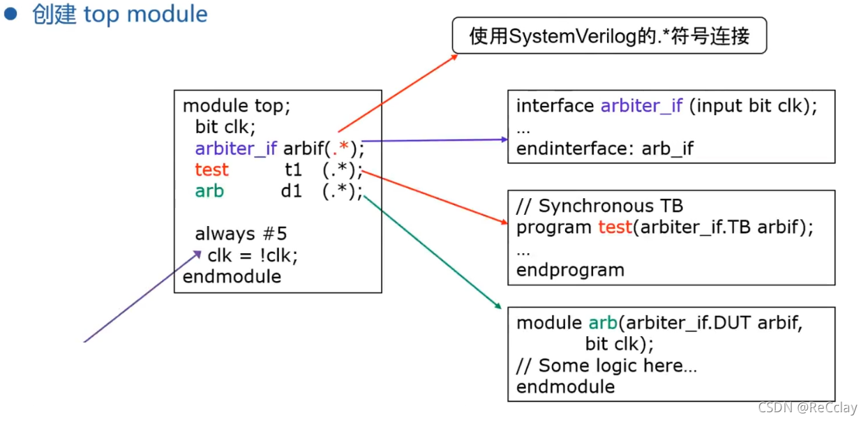
2.6、 Verification platform - Top level documents top
- Top level example , It has nothing to do with the following
2.6.1、RTL Design with Interface
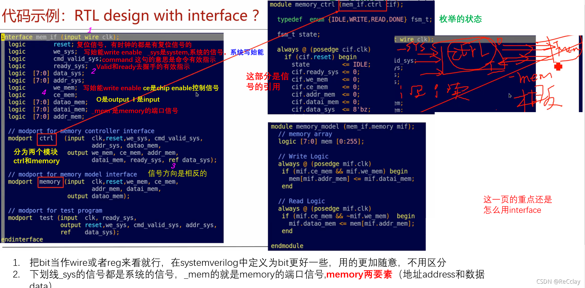
refstay SV Middle is equivalent toinout- ref Parameter passing variable pointer , Not the value of the variable , Reference resources C The pointer to language , stay Interface Not much used in !
- In practice, ,RTL Design In Chinese Interface Very few , Here is just an example !
Code example block diagram relationship :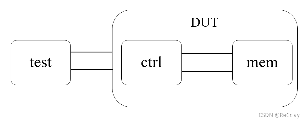
2.6.2、Test Program with Interface
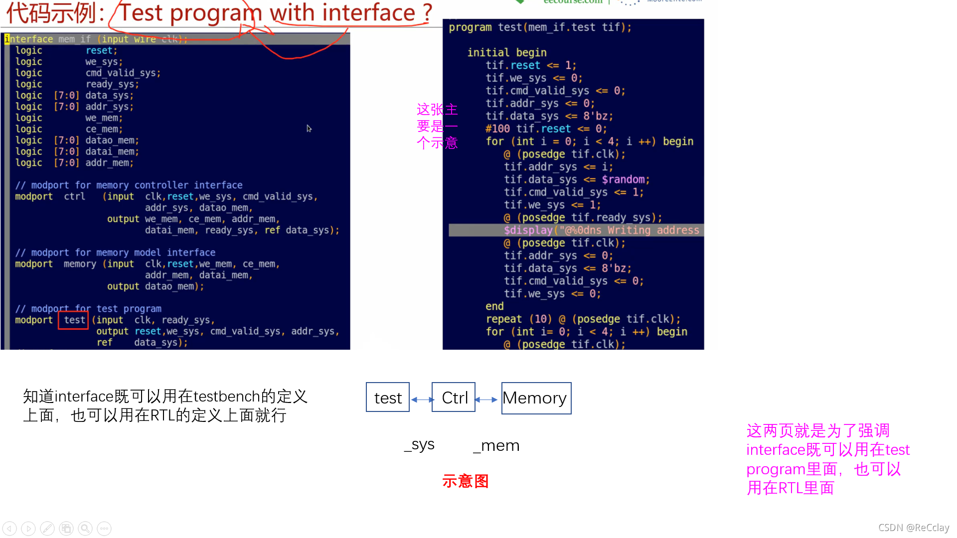
2.6.3、Connection between DUT & test with interface
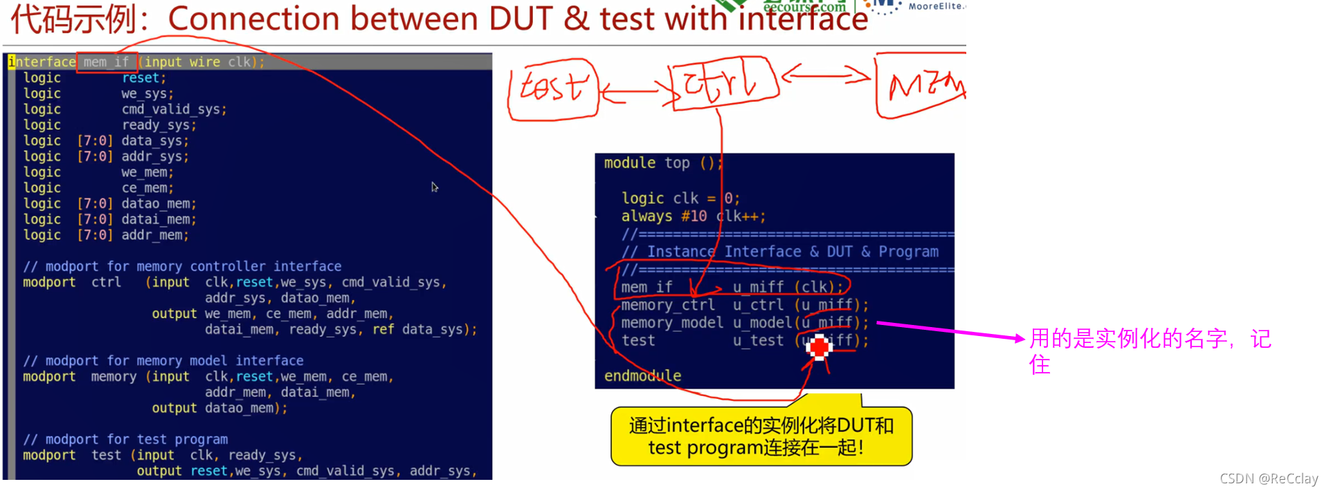
- Q:test and ctrl How are the signals connected ?
- A: By means of Interface Medium modport Define the direction , Can realize automatic connection !
3、 ... and 、 Practice
3.1、 To write DUT file
arb.v
module arb(
  input  wire rst_n,
  input  wire clk,
  input  wire request,
  output reg grant
);
always @(posedge clk or negedge rst_n) begin
if(rst_n 1‘b0) begin
grant <= 1’b0;
end
else if(request 1‘b1)begin
grant <= 1’b1;
end
else if(request ==1‘b0)begin
grant <= 1’b0;
end
end
- 1
- 2
- 3
- 4
- 5
- 6
- 7
- 8
- 9
- 10
- 11
- 12
- 13
- 14
- 15
- 16
- 17
- 18
3.2、 To write Interface file
arb_if.sv
interface arb_if(input bit clk);
  logic grant;
  logic request;
  logic rst_n;
  clocking cb @(posedge clk);
    input grant;
    output request;
  endclocking
  modport TB(
    clocking cb,
    output rst_n
  );
  modport dut(
    output grant,
    input request,
    input rst_n
  );
endinterface
- DUT Of port Generally, I won't use Interface Of port, This clocking It's just aimed at test Use defined !
- clocking The essence is to simulate the clock edge , Beat the signal in . and DUT The port signal actually does not contain timing information , If you want to beat with the clock after you come in , Is to use the actual circuit , That is, the actual D Trigger to shoot . No need to beat with an analog clock !
- clocking Generally used in the environment , Synchronous timing of analog clock beating ; Not necessarily test It needs to be used inside clocking, Flexible applications , Sure Interface There's no clocking, stay driver Go inside and send data along the clock ; It only provides choices grammatically
- About DUT Of modport What I want to say is :DUT It doesn't work clocking block Of ,DUT It's internal use always Logic to pick , Therefore, it cannot be used on the port cb.
- In fact, the
modport dutNot much use !
3.3、 To write test file
notes : The function is mainly used to send incentives
test.sv
program test(arb_if.TB arbif);
  initial begin
    // Asynch drive rst_n
    arbif.cb.request <= 1'b0; arbif.rst_n <= 1'b1;
    #15 arbif.rst_n <= 1'b0;
    #35 arbif.rst_n <= 1'b1;
    #5;
    // Synch drive request
    arbif.cb.request <= 1'b1; wait(arbif.cb.grant == 1'b1);
    arbif.cb.request <= 1'b0;
    @arbif.cb; //@(posedge clk)
    @arbif.cb;
    @arbif.cb;
  end
endprogram
3.4、 To write TestBench file
arb_tb.sv
module ARB_TB();
  bit clk;
  arb_if arbif(.*);// arb_if arbif(.clk(clk));
  test u_test(.*);
  arb u_arb(
    .rst_n (arbif.rst_n),
    .clk   (clk),
    .request (arbif.request),
    .grant (arbif.grant)
  );
  initial begin
    clk = 0;
    forever #10 clk = ~clk;
  end
endmodule
.*Will automatically connect Interface The signal inside !
3.5、 Compile operation
Because I just wrote test Motivation of , Didn't write monitior, There is no automatic comparison Makefile, Therefore use Questasim To see the waveform , The opening command is as follows
vsim &
- 1
If Questasim Some projects have been started , Need to close first , And then use GUI A new project . Reference resources :【 Numbers IC Verify the quick start 】6、Questasim Quick to use
Follow the link above to create a new 、 Compile and start the simulation project .
add to DUT The waveform of , stay sim Window selected u_arb, choice Add Wave Or shortcut key ctrl+w, As shown in the figure below :
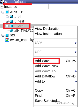
Later on Wave Column selection Run -ALL, Whether to end the simulation appears , Be sure to choose NO, As shown in the figure below :


You can contrast DUT Code , Check the waveform , Can be found to meet expectations
边栏推荐
猜你喜欢
【数字IC验证快速入门】11、Verilog TestBench(VTB)入门
What is the function of paralleling a capacitor on the feedback resistance of the operational amplifier circuit
漏洞复现-Fastjson 反序列化

【雅思口语】安娜口语学习记录 Part2
JS quick start (I)

LeetCode简单题之判断一个数的数字计数是否等于数位的值
Main window in QT learning 27 application

Interactive book delivery - signed version of Oracle DBA work notes

漏洞複現-Fastjson 反序列化

Fast parsing intranet penetration escorts the document encryption industry
随机推荐
JS quick start (I)
Lattice coloring - matrix fast power optimized shape pressure DP
Complex network modeling (II)
Myabtis_ Plus
game攻防世界逆向
LeetCode简单题之字符串中最大的 3 位相同数字
Lua 编程学习笔记
Qinglong panel -- Huahua reading
Complex network modeling (III)
Rainbond 5.7.1 支持对接多家公有云和集群异常报警
柯基数据通过Rainbond完成云原生改造,实现离线持续交付客户
Game attack and defense world reverse
jeeSite 表单页面的Excel 导入功能
使用 Nocalhost 开发 Rainbond 上的微服务应用
轻松上手Fluentd,结合 Rainbond 插件市场,日志收集更快捷
JS cross browser parsing XML application
Network learning (II) -- Introduction to socket
Example of file segmentation
[step on the pit series] H5 cross domain problem of uniapp
Qinglong panel -- finishing usable scripts