当前位置:网站首页>Design intelligent weighing system based on Huawei cloud IOT (STM32)
Design intelligent weighing system based on Huawei cloud IOT (STM32)
2022-07-07 11:18:00 【InfoQ】
1. Preface
2. Hardware selection
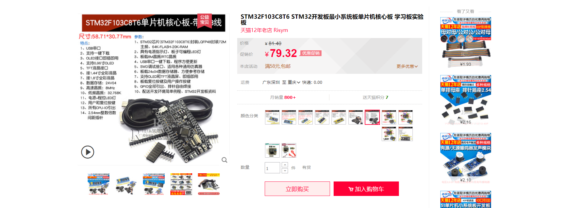
2.1 STM32F103C8T6
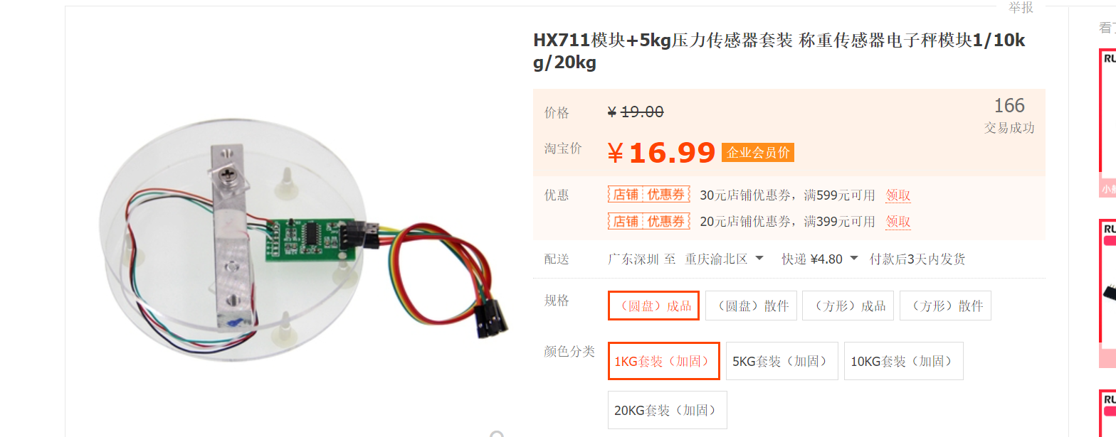
2.2 Scale sensor
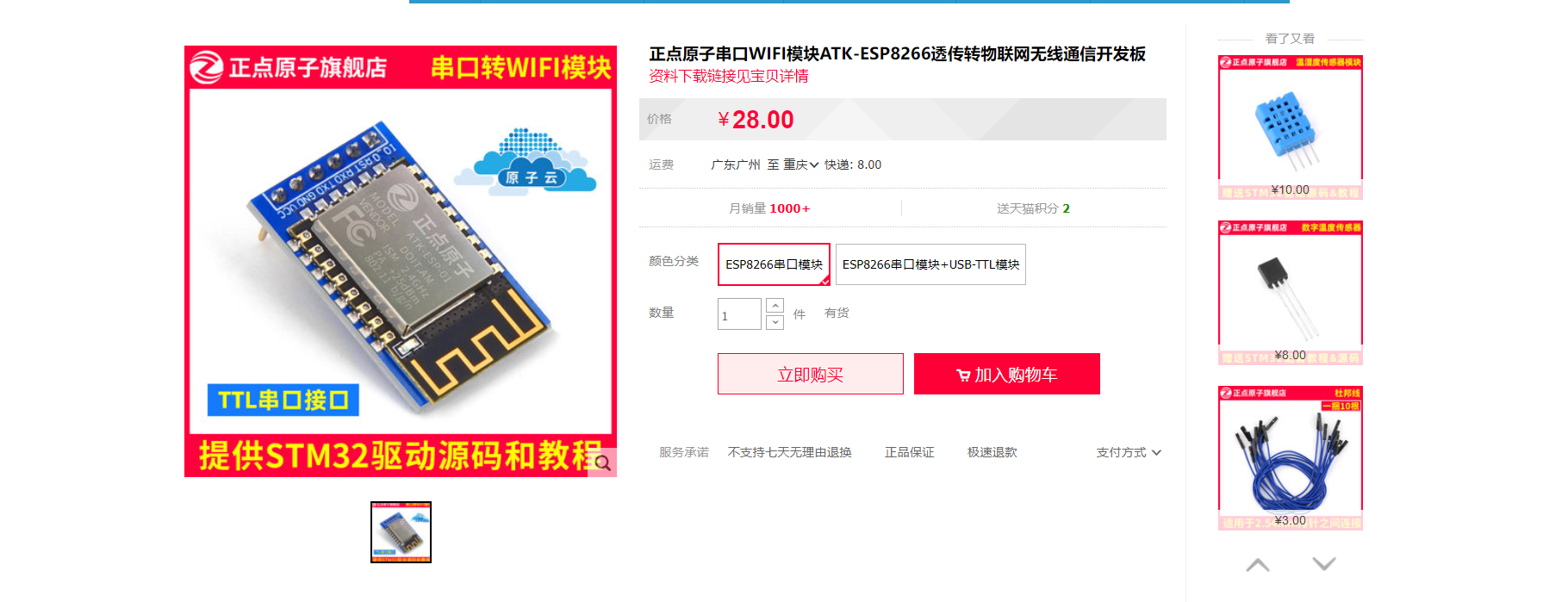
2.3 ESP8266-wifi
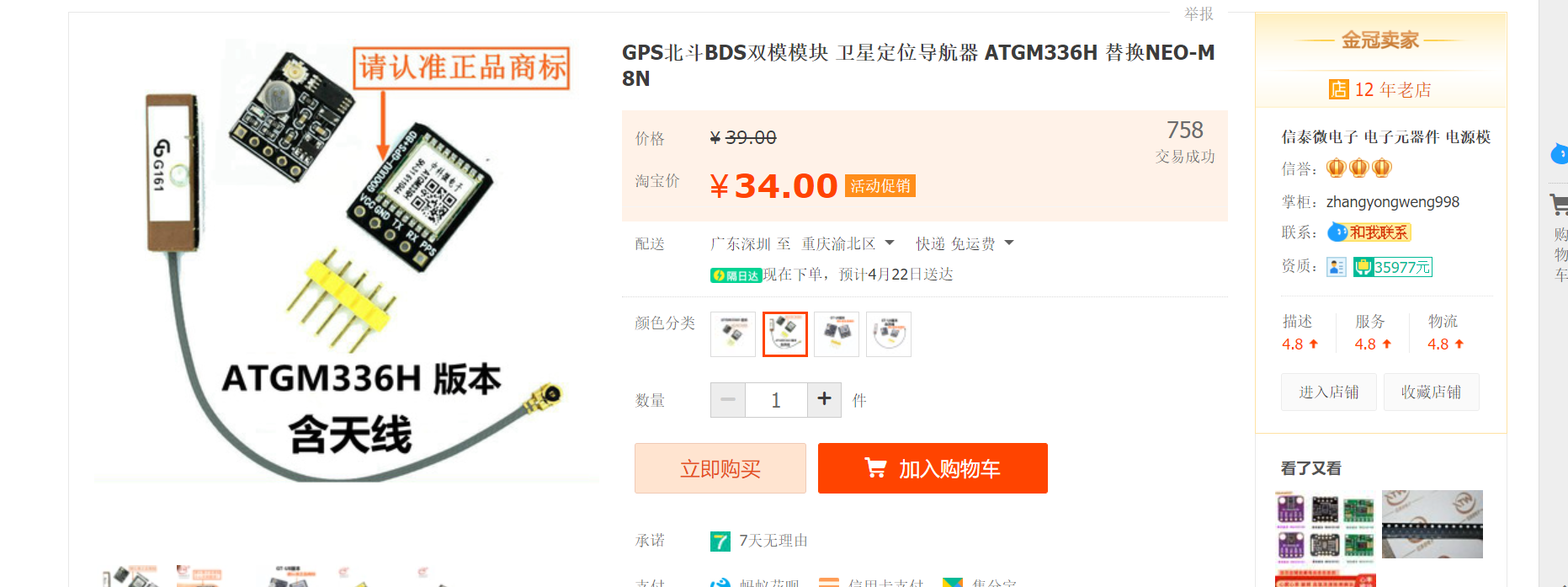
2.4 GPS modular
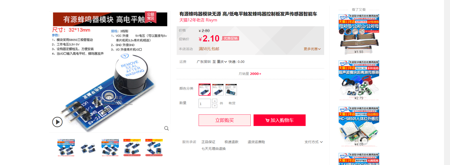
2.5 Buzzer
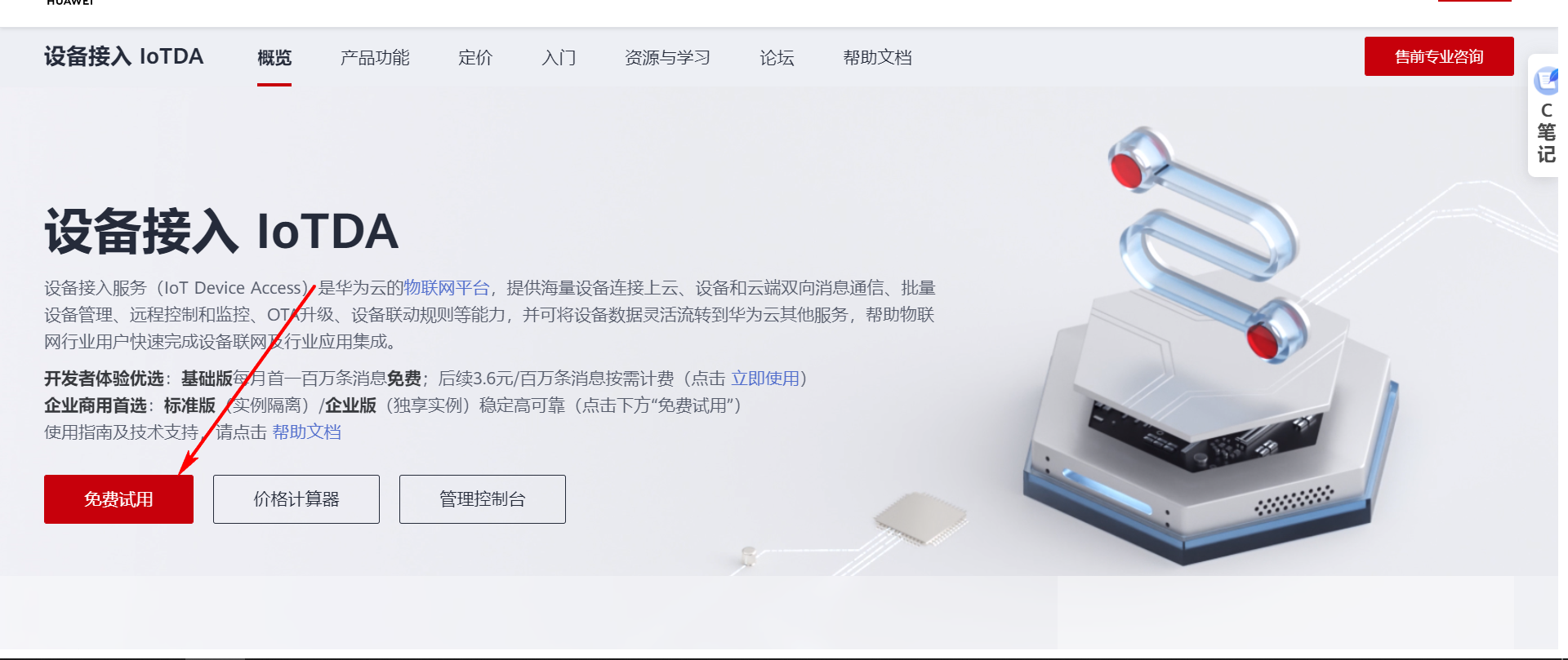
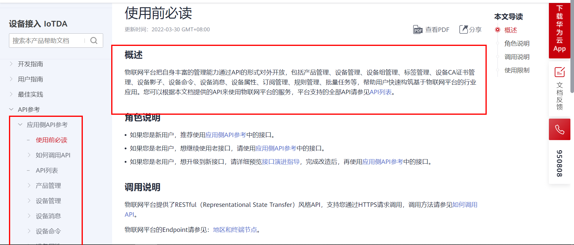
3. Create cloud products and devices
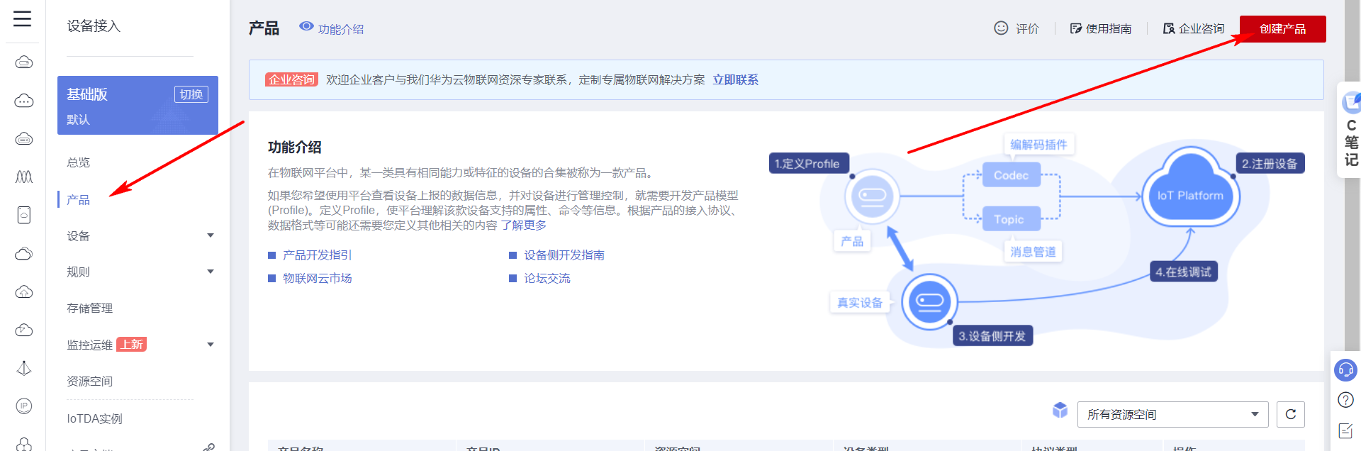
3.1 Create products

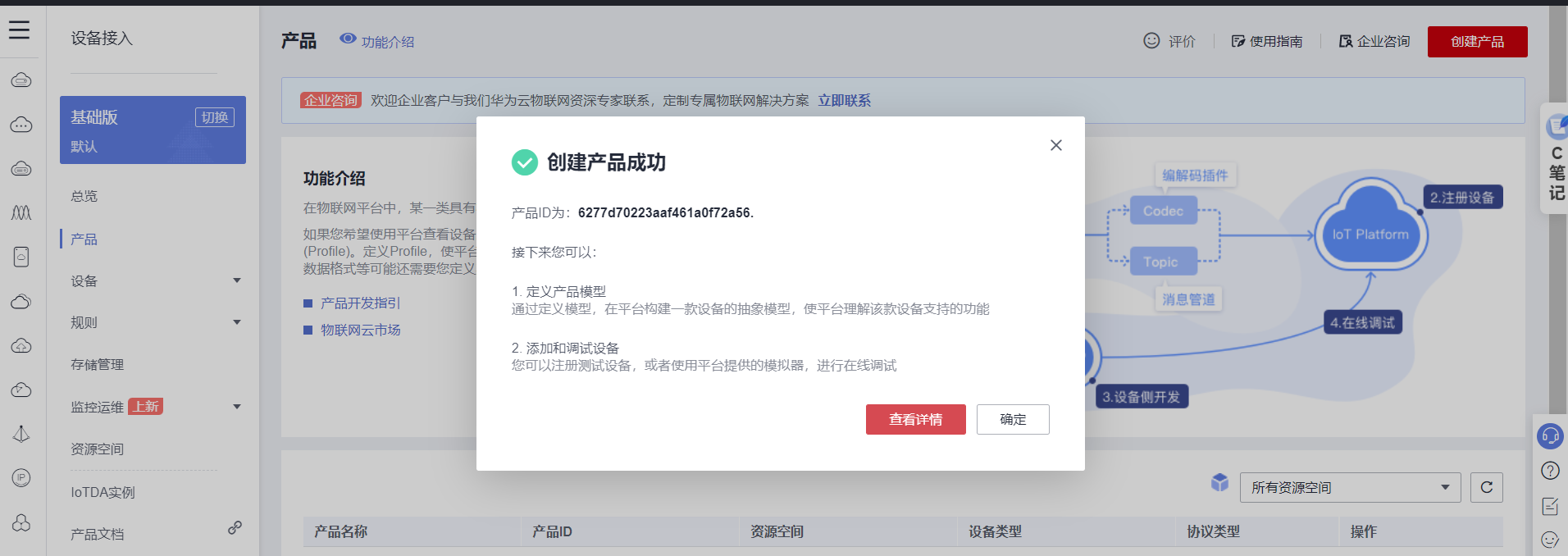
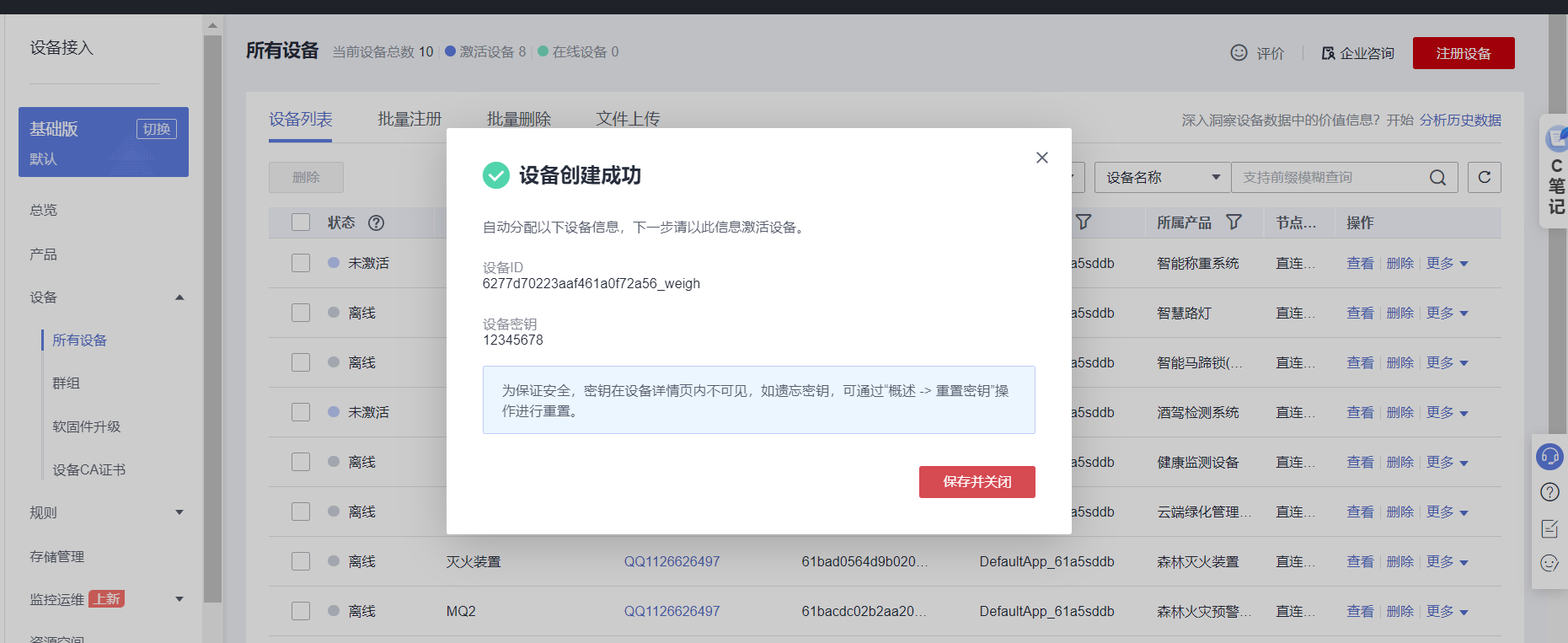
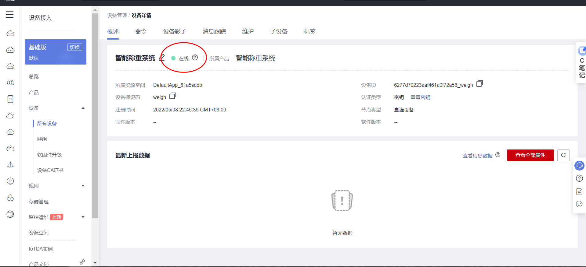
3.2 Create device
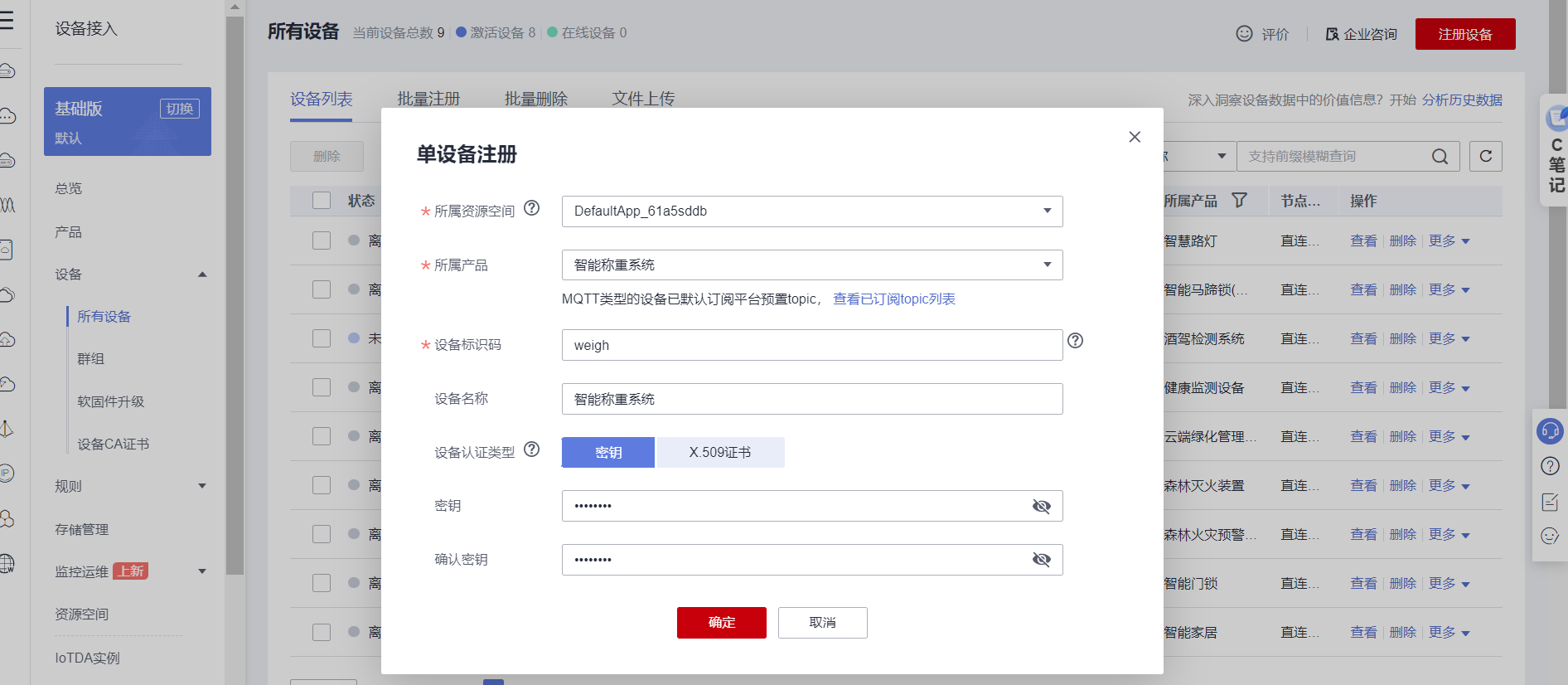
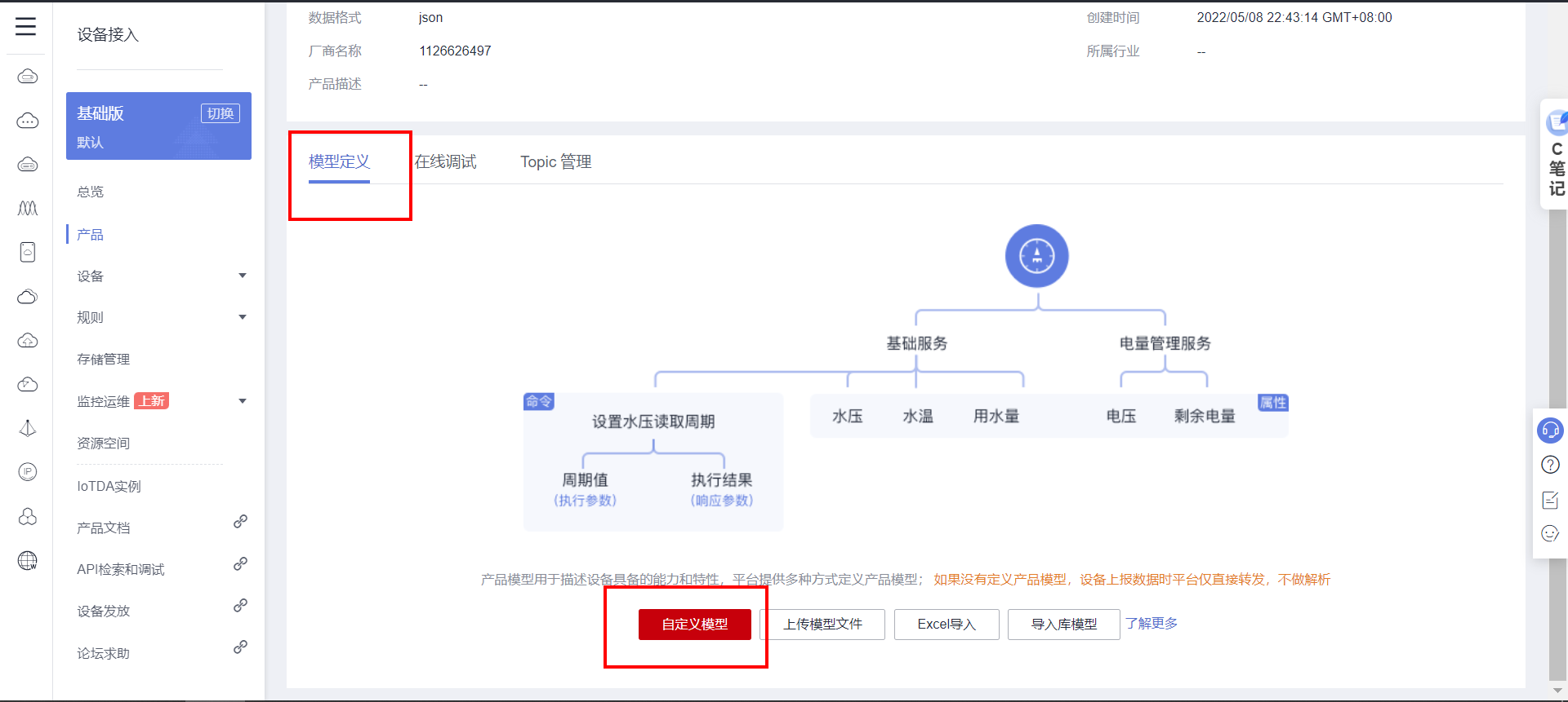
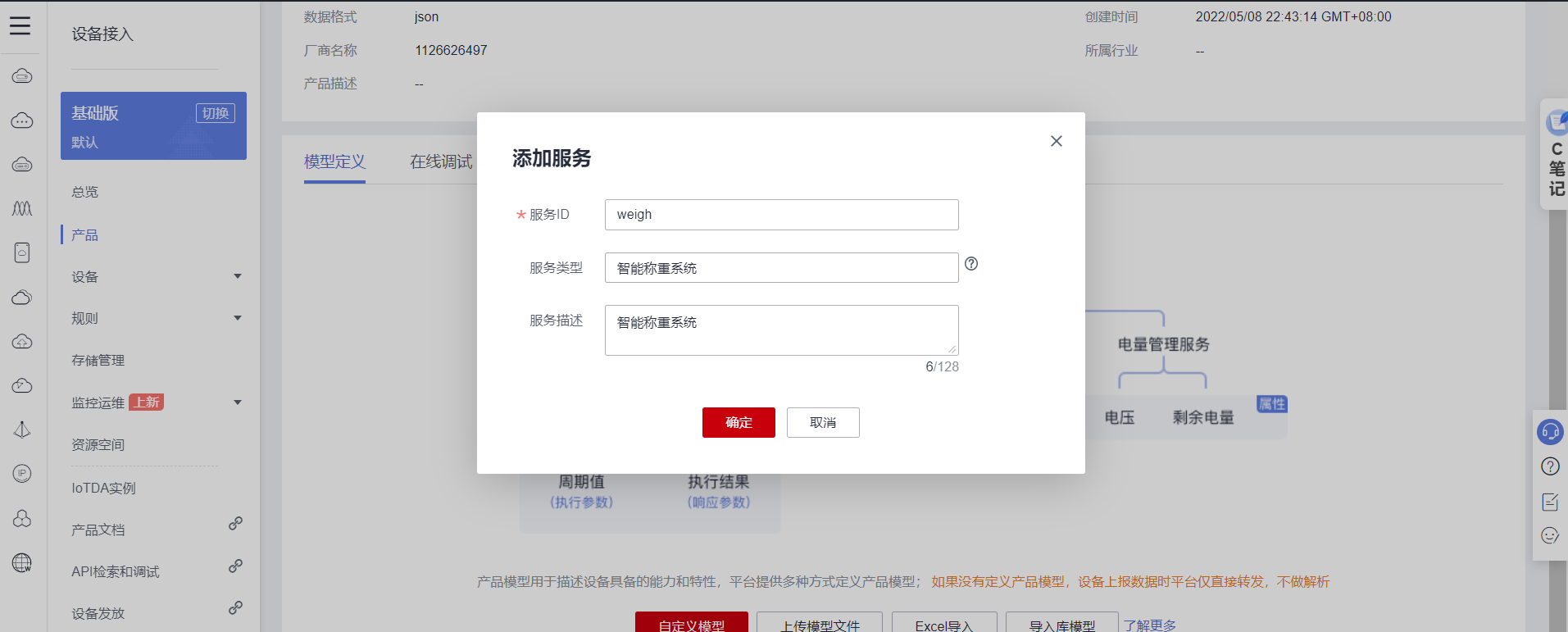
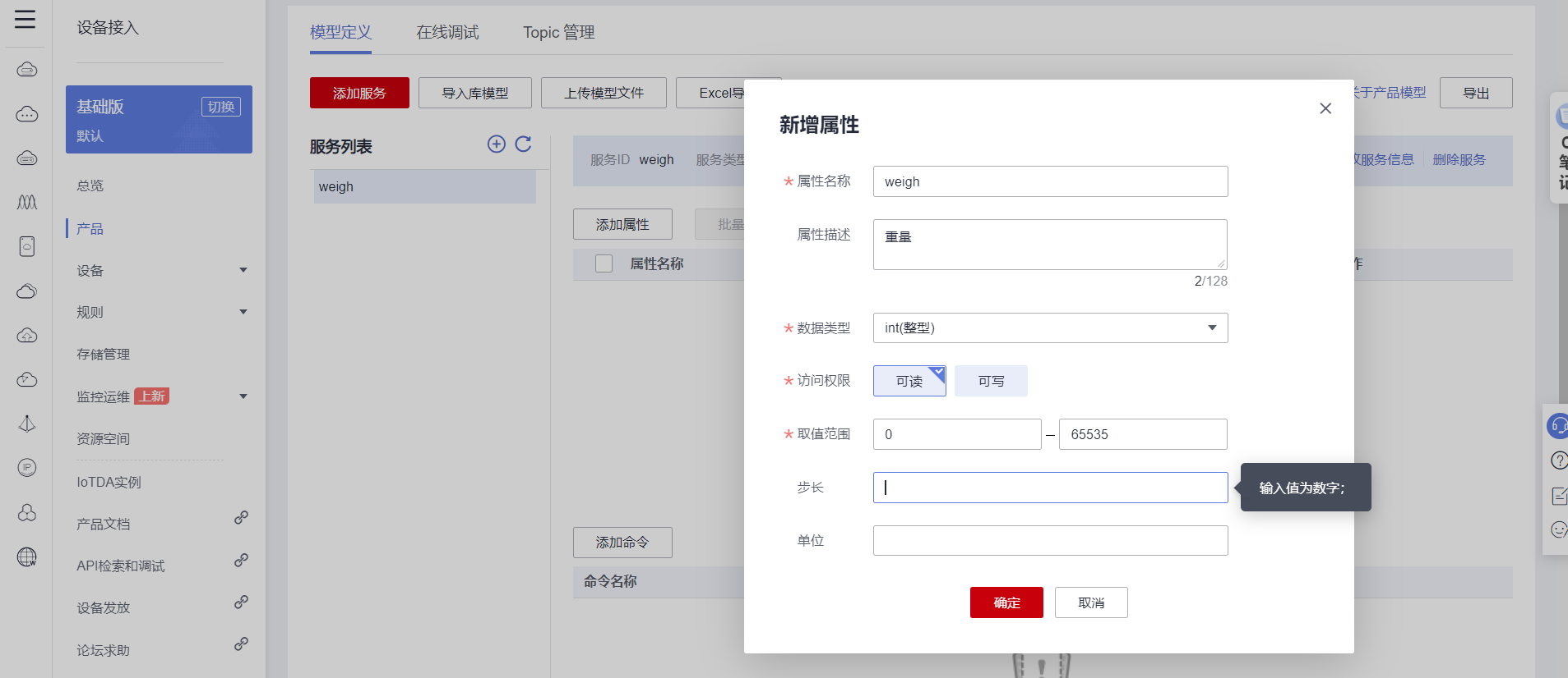
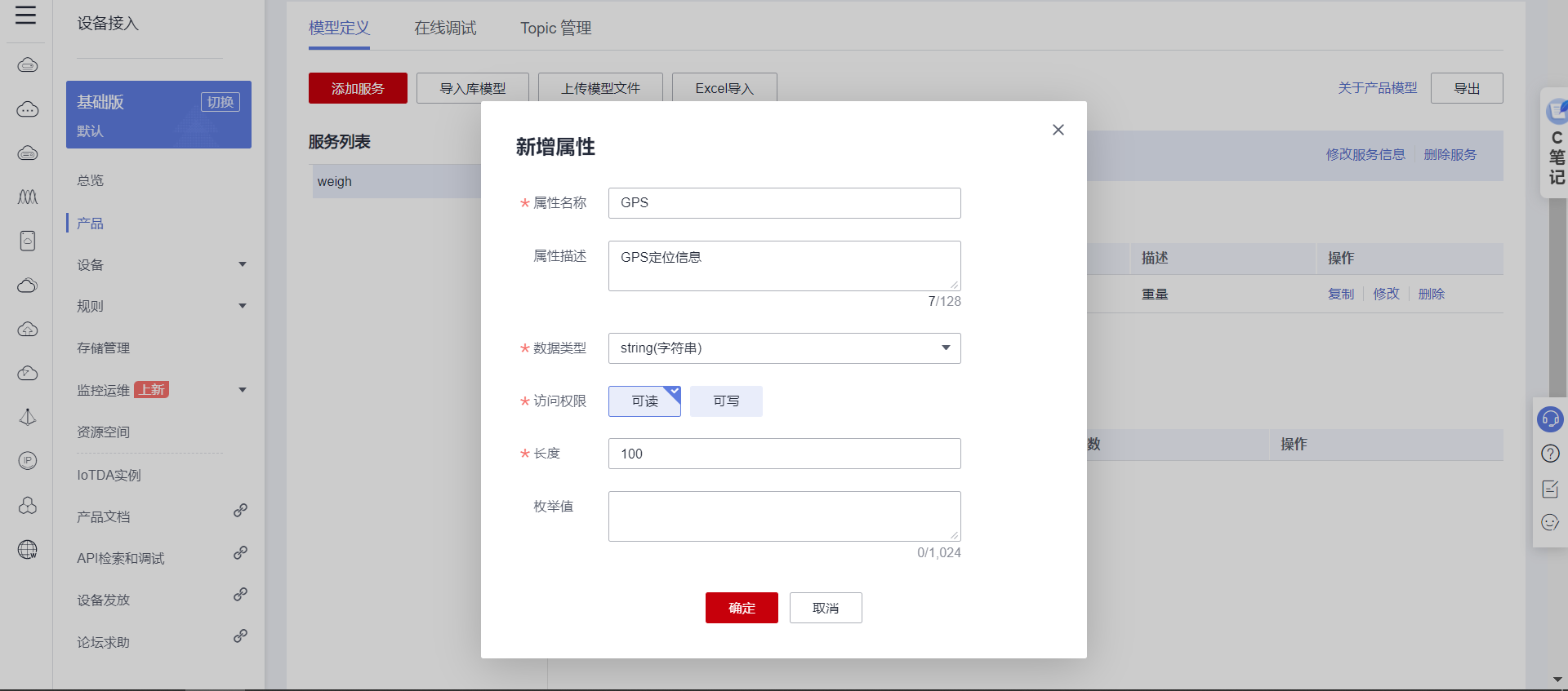
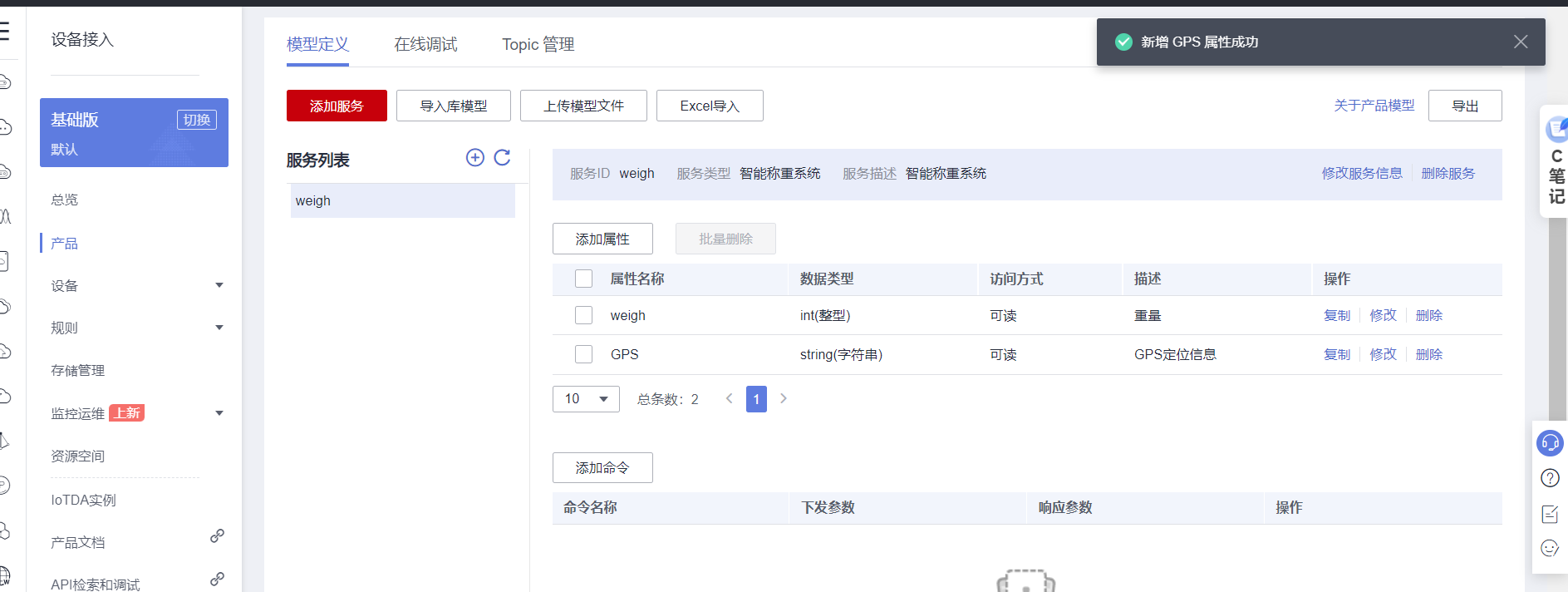
3.3 Custom model data
{
 "device_id": "6277d70223aaf461a0f72a56_weigh",
 "secret": "12345678"
}

 service ID: weigh
 The attribute name   data type   access   describe
weigh int( integer )  Can be read   weight
GPS string( character string )  Can be read  GPS Location information
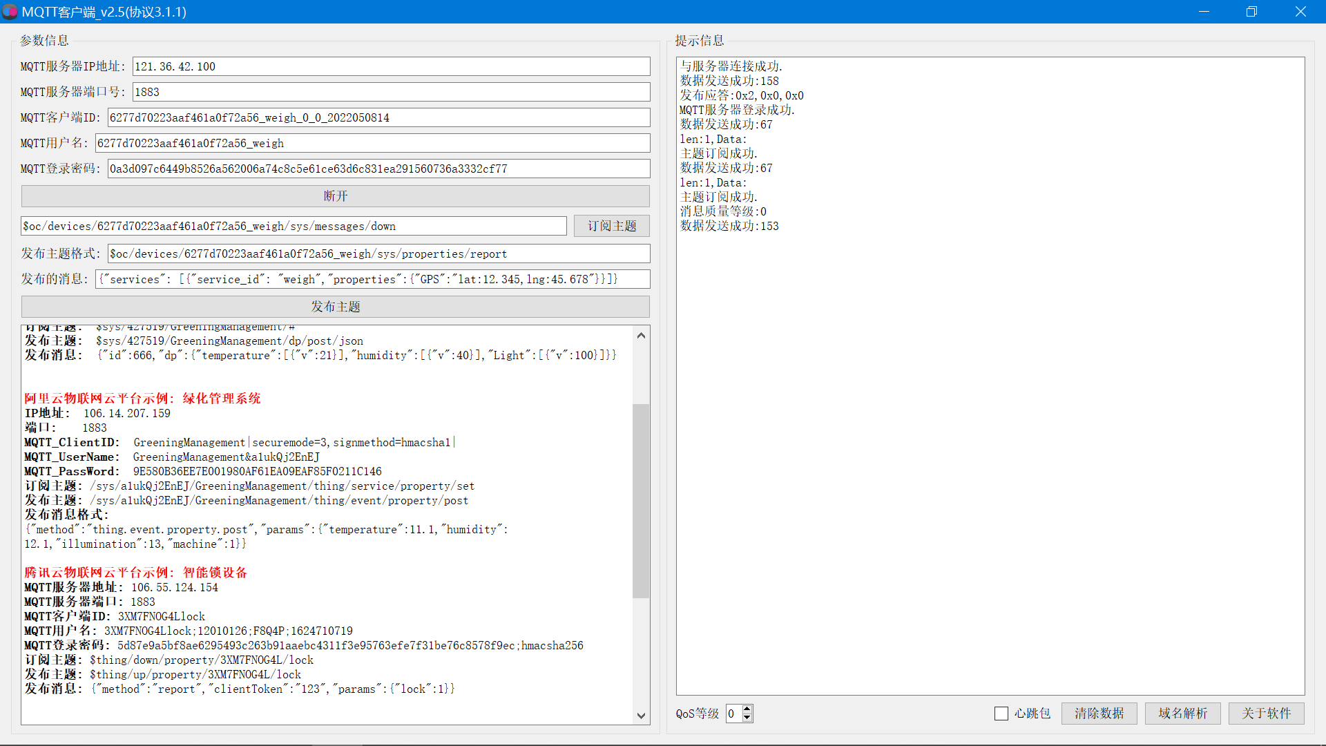
3.4 MQTT Key generation
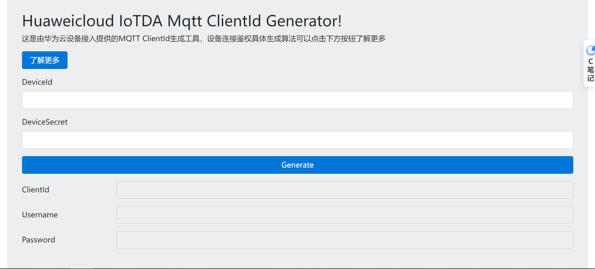
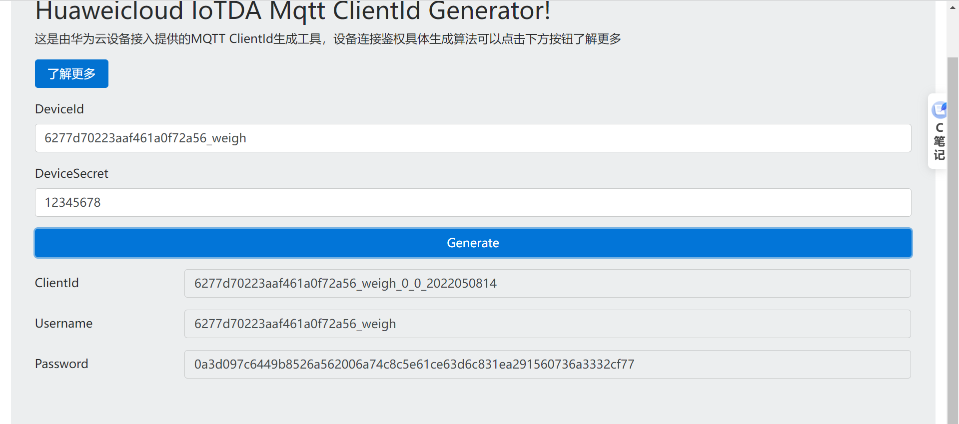
DeviceId 6277d70223aaf461a0f72a56_weigh
DeviceSecret 12345678
ClientId 6277d70223aaf461a0f72a56_weigh_0_0_2022050814
Username 6277d70223aaf461a0f72a56_weigh
Password 0a3d097c6449b8526a562006a74c8c5e61ce63d6c831ea291560736a3332cf77
161a58a78.iot-mqtts.cn-north-4.myhuaweicloud.com121.36.42.100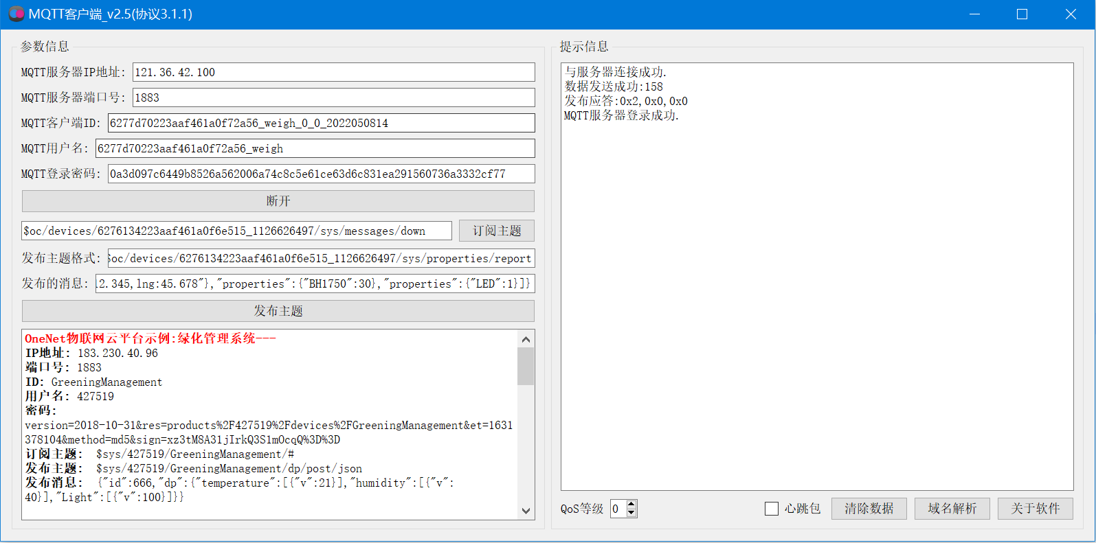
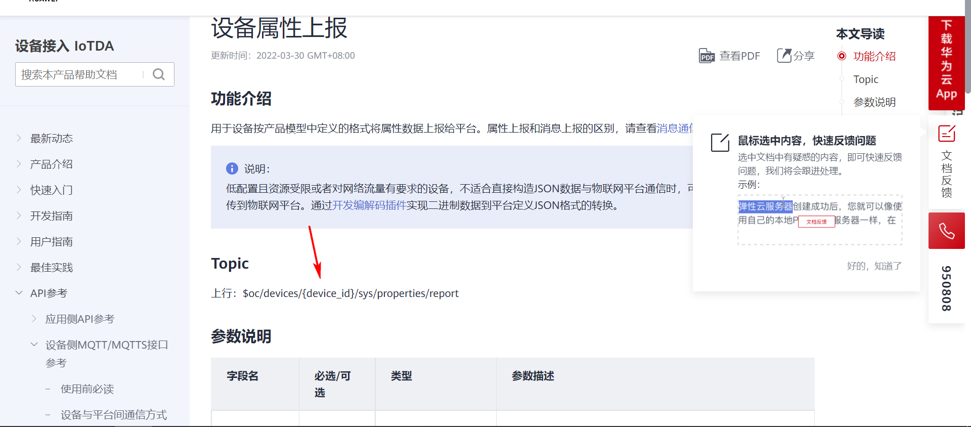
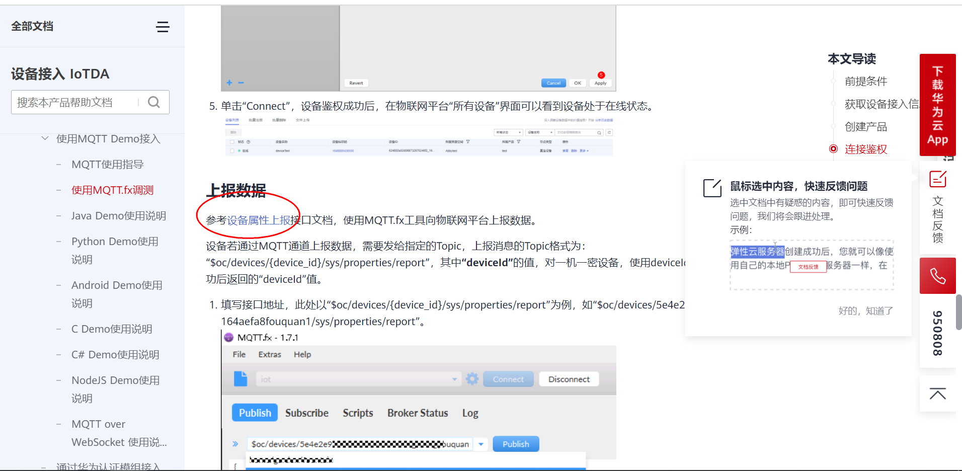
3.5 Topic subscription and Publishing
// Subscribe to topics :  The platform sends a message to the device
$oc/devices/6277d70223aaf461a0f72a56_weigh/sys/messages/down
// Equipment report data
$oc/devices/6277d70223aaf461a0f72a56_weigh/sys/properties/report
// Reported attribute message  ( Multiple attributes can be reported at a time , stay json Just add it to the )
{"services": [{"service_id": "weigh","properties":{"GPS":"lat:12.345,lng:45.678"}}]}
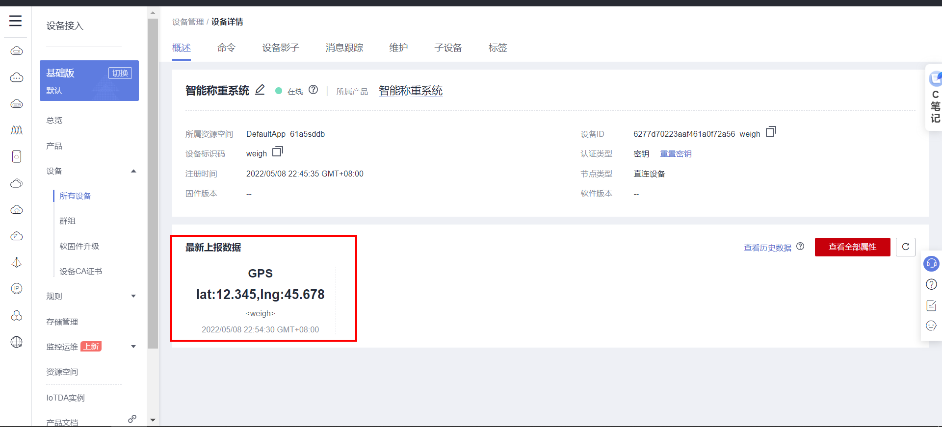
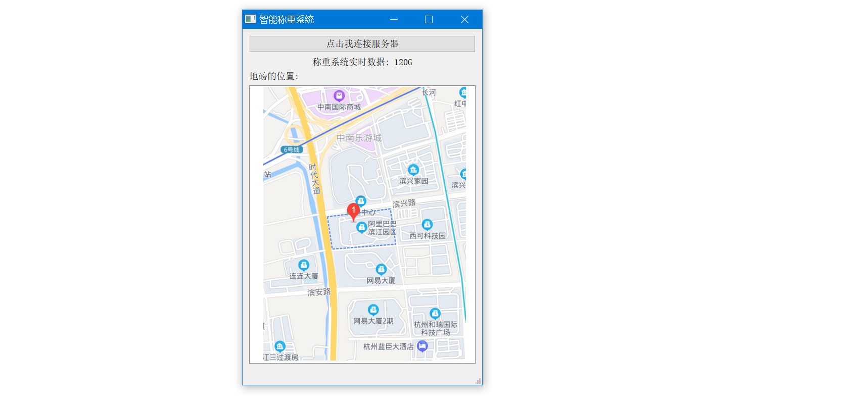
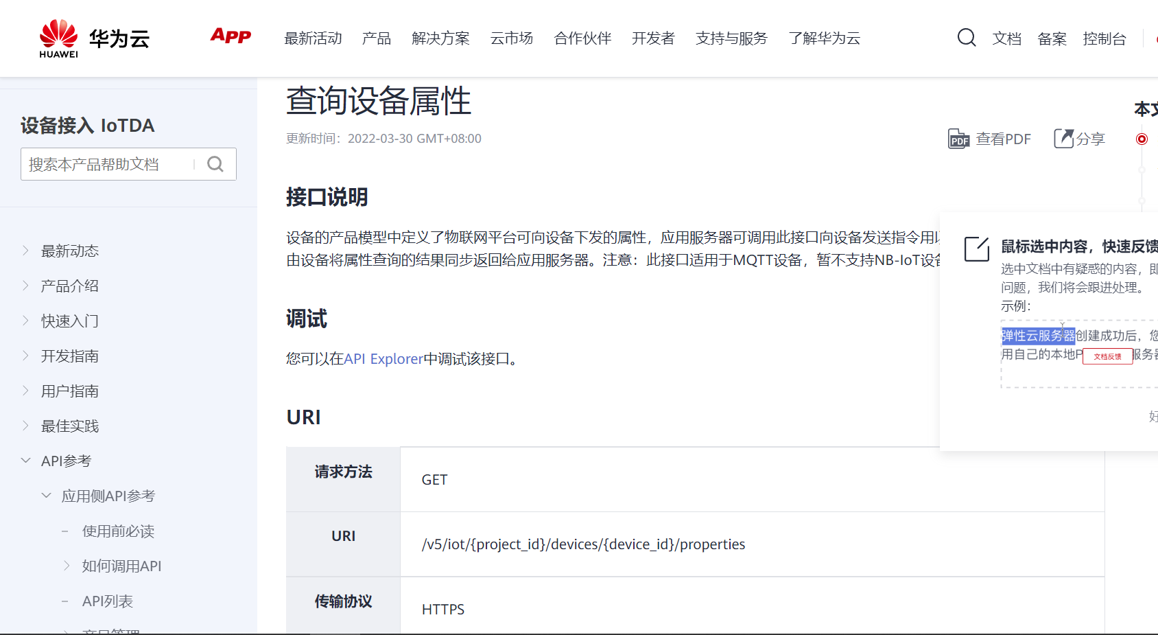
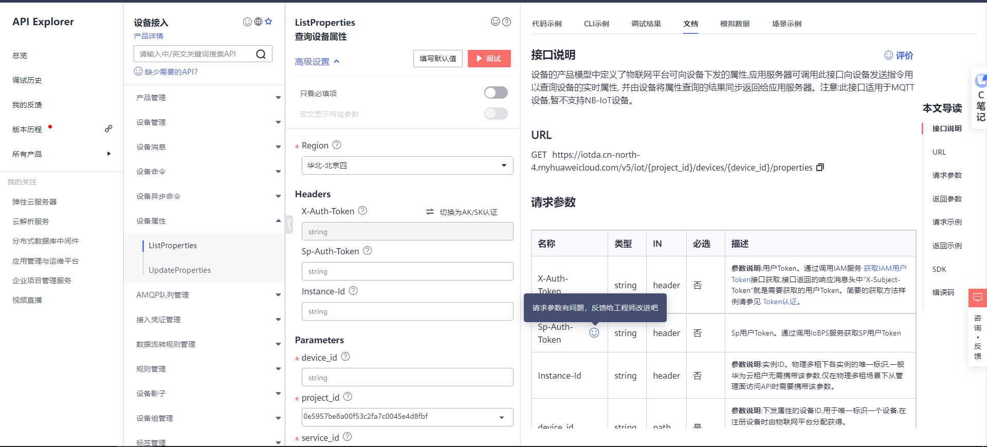
3.6 Application side development
4. STM32 Device side development
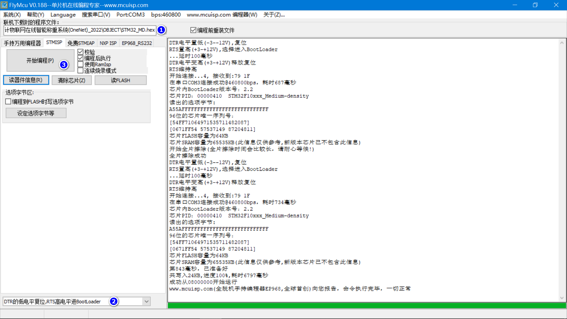
4.1 Program download
4.2 Schematic diagram
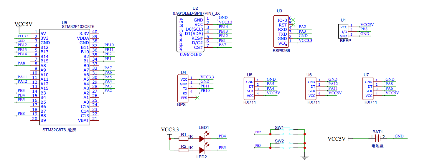
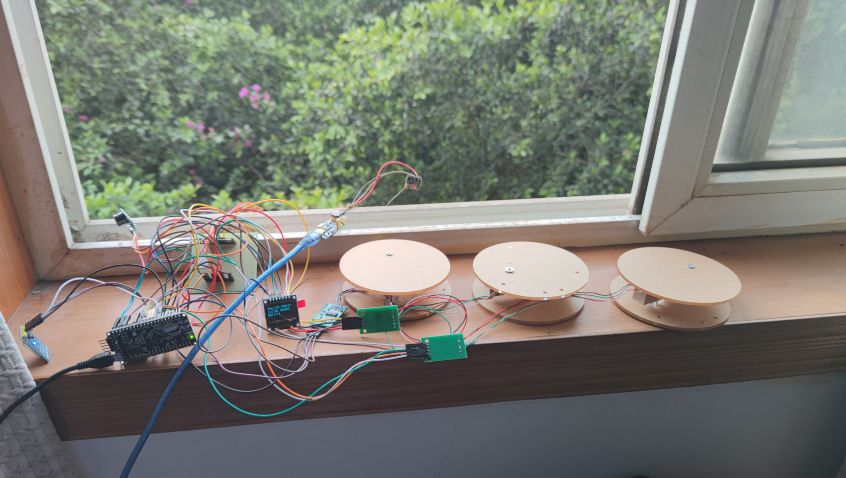
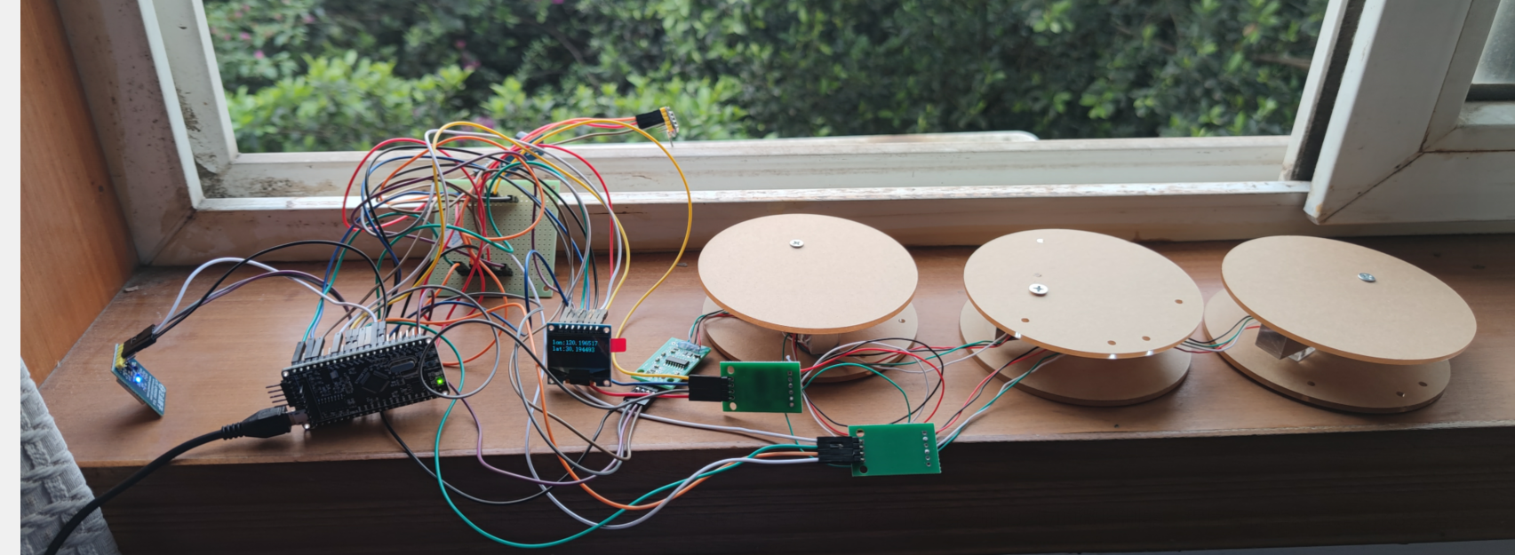
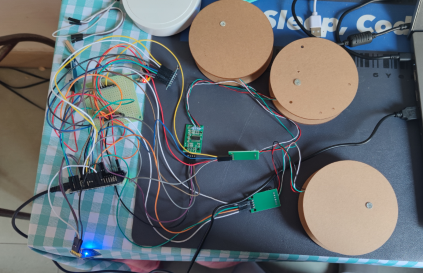
4.3 Hardware wiring
(1)OLED Display wiring :
D0----(SCK)------------------->>PB14
D1----(MOSI)------------------>>PB13
RES—( Low level of reset pin is effective )-------->>PB12
DC--( Data and command control pins )------>>PB1
CS--( Chip selection pin )---------------->>PA7
GND--------------------------->>GND
VCC--------------------------->>3.3V perhaps 5V

(2)ATK-ESP8266 WIFI connection
PA2(TX)--RXD  Module receiving pin
PA3(RX)--TXD  Module sending pin
GND---GND  The earth
VCC---VCC  Power Supply (3.3V~5.0V)

(3) External buzzer module :  High level response
BEEP----->PB8

(4) External keys :
KEY1 -PB3  Pressing is low   Zero clearing
KEY2 -PB2  Pressing is low   Page turning
KEY3 -PB6  Pressing is low   Add
KEY4 -PB7  Pressing is low   reduce

(5) external LED Light module :
LED1-PB4  Low level light
LED2-PB5  Low level light

(6) The weighing sensor 1
VCC--->5V
SCK--->PA4  Timing control pin -- Yes STM32-- The output mode
DT---->PA5  Output pin - Yes STM32-- The input mode
GND--->GND

(7) The weighing sensor 2
VCC--->5V
SCK--->PA11  Timing control pin -- Yes STM32-- The output mode
DT---->PA12  Output pin - Yes STM32-- The input mode
GND--->GND

(8) The weighing sensor 3
VCC--->5V
SCK--->PA6  Timing control pin -- Yes STM32-- The output mode
DT---->PA8  Output pin - Yes STM32-- The input mode
GND--->GND

(9)GPS Module wiring instructions
GND----GND
VCC---3.3V
PB11----GPS_TX
PB10----GPS_RX

(--) On board LED The lamp : Low level light
LED1--PC13
BEEP2--PC14

(--) Onboard keys :
KEY1--PA0  Press to high level
4.4 MQTT Connection code
#include "stm32f10x.h"
#include "led.h"
#include "delay.h"
#include "key.h"
#include "usart.h"
#include <string.h>
#include "timer.h"
#include "bluetooth.h"
#include "esp8266.h"
#include "mqtt.h"
// Equipment information of Huawei Internet of things server
#define MQTT_ClientID "61b9ba3a2b2aa20288c1e7f1_QQ1126626497_0_0_2021121510"
#define MQTT_UserName "61b9ba3a2b2aa20288c1e7f1_QQ1126626497"
#define MQTT_PassWord "385ce91dfe7da5b7431868d5d87e7998163c493344040935d5a00024d6324242"
// Topics subscribed and published
#define SET_TOPIC "$oc/devices/61b9ba3a2b2aa20288c1e7f1_QQ1126626497_0_0_2021121510/sys/messages/down" // subscribe
#define POST_TOPIC "$oc/devices/61b9ba3a2b2aa20288c1e7f1_QQ1126626497_0_0_2021121510/sys/properties/report" // Release
char mqtt_message[200];// Report data buffer
int main()
{
u32 time_cnt=0;
u32 i;
u8 key;
LED_Init();
BEEP_Init();
KEY_Init();
USART1_Init(115200);
TIMER1_Init(72,20000); // Timeout time 20ms
USART2_Init(9600);// A serial port - bluetooth
TIMER2_Init(72,20000); // Timeout time 20ms
USART3_Init(115200);// A serial port -WIFI
TIMER3_Init(72,20000); // Timeout time 20ms
USART1_Printf(" Initializing WIFI One moment please .\n");
if(ESP8266_Init())
{
USART1_Printf("ESP8266 Hardware detection error .\n");
}
else
{
// Unencrypted port
USART1_Printf("WIFI:%d\n",ESP8266_STA_TCP_Client_Mode("CMCC-Cqvn","99pu58cb","121.36.42.100",1883,1));
}
//2. MQTT Protocol initialization
MQTT_Init();
//3. Connect to Huawei server
while(MQTT_Connect(MQTT_ClientID,MQTT_UserName,MQTT_PassWord))
{
USART1_Printf(" Server connection failed , Retrying ...\n");
delay_ms(500);
}
USART1_Printf(" Server connection successful .\n");
//3. Subscribe to topics
if(MQTT_SubscribeTopic(SET_TOPIC,0,1))
{
USART1_Printf(" Topic subscription failed .\n");
}
else
{
USART1_Printf(" Topic subscription succeeded .\n");
}
.........
4.5 ESP8266 Code
#include "esp8266.h"
u8 ESP8266_IP_ADDR[16]; //255.255.255.255
u8 ESP8266_MAC_ADDR[18]; // Hardware address
/*
The functionality : ESP8266 Command sending function
Function return value :0 It means success 1 It means failure
*/
u8 ESP8266_SendCmd(char *cmd)
{
u8 i,j;
for(i=0;i<10;i++) // Number of tests -- Number of times the command was sent
{
USARTx_StringSend(USART3,cmd);
for(j=0;j<100;j++) // Waiting time
{
delay_ms(50);
if(USART3_RX_FLAG)
{
USART3_RX_BUFFER[USART3_RX_CNT]='\0';
USART3_RX_FLAG=0;
USART3_RX_CNT=0;
if(strstr((char*)USART3_RX_BUFFER,"OK"))
{
return 0;
}
}
}
}
return 1;
}
/*
The functionality : ESP8266 Hardware initialization detection function
Function return value :0 It means success 1 It means failure
*/
u8 ESP8266_Init(void)
{
// Exit through mode
USARTx_StringSend(USART3,"+++");
delay_ms(50);
return ESP8266_SendCmd("AT\r\n");
}
/*
The functionality : One click configuration WIFI by AP+TCP Server mode
Function parameter :
char *ssid Created hotspot name
char *pass Create a new hotspot password ( least 8 position )
u16 port Created server port number
Function return value : 0 It means success Other values represent the corresponding error value
*/
u8 ESP8266_AP_TCP_Server_Mode(char *ssid,char *pass,u16 port)
{
char *p;
u8 i;
char ESP8266_SendCMD[100]; // Combine commands in the sending process
/*1. Test the hardware */
if(ESP8266_SendCmd("AT\r\n"))return 1;
/*2. Close back display */
if(ESP8266_SendCmd("ATE0\r\n"))return 2;
/*3. Set up WIFI Pattern */
if(ESP8266_SendCmd("AT+CWMODE=2\r\n"))return 3;
/*4. Reset */
ESP8266_SendCmd("AT+RST\r\n");
delay_ms(1000);
delay_ms(1000);
delay_ms(1000);
/*5. Close back display */
if(ESP8266_SendCmd("ATE0\r\n"))return 5;
/*6. Set up WIFI Of AP Mode parameters */
sprintf(ESP8266_SendCMD,"AT+CWSAP=\"%s\",\"%s\",1,4\r\n",ssid,pass);
if(ESP8266_SendCmd(ESP8266_SendCMD))return 6;
/*7. Open multiple connections */
if(ESP8266_SendCmd("AT+CIPMUX=1\r\n"))return 7;
/*8. Set the server port number */
sprintf(ESP8266_SendCMD,"AT+CIPSERVER=1,%d\r\n",port);
if(ESP8266_SendCmd(ESP8266_SendCMD))return 8;
/*9. Query local IP Address */
if(ESP8266_SendCmd("AT+CIFSR\r\n"))return 9;
// extract IP Address
p=strstr((char*)USART3_RX_BUFFER,"APIP");
if(p)
{
p+=6;
for(i=0;*p!='"';i++)
{
ESP8266_IP_ADDR[i]=*p++;
}
ESP8266_IP_ADDR[i]='\0';
}
// extract MAC Address
p=strstr((char*)USART3_RX_BUFFER,"APMAC");
if(p)
{
p+=7;
for(i=0;*p!='"';i++)
{
ESP8266_MAC_ADDR[i]=*p++;
}
ESP8266_MAC_ADDR[i]='\0';
}
// Print general information
USART1_Printf(" At present WIFI Pattern :AP+TCP The server \n");
USART1_Printf(" At present WIFI Hot spot name :%s\n",ssid);
USART1_Printf(" At present WIFI Hot code :%s\n",pass);
USART1_Printf(" At present TCP Server port number :%d\n",port);
USART1_Printf(" At present TCP The server IP Address :%s\n",ESP8266_IP_ADDR);
USART1_Printf(" At present TCP The server MAC Address :%s\n",ESP8266_MAC_ADDR);
return 0;
}
/*
The functionality : TCP Sending function in server mode
Send instructions :
*/
u8 ESP8266_ServerSendData(u8 id,u8 *data,u16 len)
{
u8 i,j,n;
char ESP8266_SendCMD[100]; // Combine commands in the sending process
for(i=0;i<10;i++)
{
sprintf(ESP8266_SendCMD,"AT+CIPSEND=%d,%d\r\n",id,len);
USARTx_StringSend(USART3,ESP8266_SendCMD);
for(j=0;j<10;j++)
{
delay_ms(50);
if(USART3_RX_FLAG)
{
USART3_RX_BUFFER[USART3_RX_CNT]='\0';
USART3_RX_FLAG=0;
USART3_RX_CNT=0;
if(strstr((char*)USART3_RX_BUFFER,">"))
{
// Continue sending data
USARTx_DataSend(USART3,data,len);
// Wait for the data to be sent successfully
for(n=0;n<200;n++)
{
delay_ms(50);
if(USART3_RX_FLAG)
{
USART3_RX_BUFFER[USART3_RX_CNT]='\0';
USART3_RX_FLAG=0;
USART3_RX_CNT=0;
if(strstr((char*)USART3_RX_BUFFER,"SEND OK"))
{
return 0;
}
}
}
}
}
}
}
return 1;
}
/*
The functionality : To configure WIFI by STA Pattern +TCP Client mode
Function parameter :
char *ssid Created hotspot name
char *pass Create a new hotspot password ( least 8 position )
char *p The server to which you will connect IP Address
u16 port The port number of the server to be connected
u8 flag 1 Indicates that transparent transmission mode is enabled 0 Indicates that the transparent transmission mode is turned off
Function return value :0 It means success Other values indicate the corresponding error
*/
u8 ESP8266_STA_TCP_Client_Mode(char *ssid,char *pass,char *ip,u16 port,u8 flag)
{
char ESP8266_SendCMD[100]; // Combine commands in the sending process
// Exit through mode
//USARTx_StringSend(USART3,"+++");
//delay_ms(50);
/*1. Test the hardware */
if(ESP8266_SendCmd("AT\r\n"))return 1;
/*2. Close back display */
if(ESP8266_SendCmd("ATE0\r\n"))return 2;
/*3. Set up WIFI Pattern */
if(ESP8266_SendCmd("AT+CWMODE=1\r\n"))return 3;
/*4. Reset */
ESP8266_SendCmd("AT+RST\r\n");
delay_ms(1000);
delay_ms(1000);
delay_ms(1000);
/*5. Close back display */
if(ESP8266_SendCmd("ATE0\r\n"))return 5;
/*6. Configure the to be connected WIFI hot spot information */
sprintf(ESP8266_SendCMD,"AT+CWJAP=\"%s\",\"%s\"\r\n",ssid,pass);
if(ESP8266_SendCmd(ESP8266_SendCMD))return 6;
/*7. Set up a single connection */
if(ESP8266_SendCmd("AT+CIPMUX=0\r\n"))return 7;
/*8. Configure the to connect TCP server information */
sprintf(ESP8266_SendCMD,"AT+CIPSTART=\"TCP\",\"%s\",%d\r\n",ip,port);
if(ESP8266_SendCmd(ESP8266_SendCMD))return 8;
/*9. Turn on transmission mode */
if(flag)
{
if(ESP8266_SendCmd("AT+CIPMODE=1\r\n"))return 9; // Turn on
if(ESP8266_SendCmd("AT+CIPSEND\r\n"))return 10; // Start penetrating
if(!(strstr((char*)USART3_RX_BUFFER,">")))
{
return 11;
}
// If you want to quit sending : "+++"
}
// Print general information
USART1_Printf(" At present WIFI Pattern :STA+TCP client \n");
USART1_Printf(" Currently connected WIFI Hot spot name :%s\n",ssid);
USART1_Printf(" Currently connected WIFI Hot code :%s\n",pass);
USART1_Printf(" Currently connected TCP Server port number :%d\n",port);
USART1_Printf(" Currently connected TCP The server IP Address :%s\n",ip);
return 0;
}
/*
The functionality : TCP Sending function in client mode
Send instructions :
*/
u8 ESP8266_ClientSendData(u8 *data,u16 len)
{
u8 i,j,n;
char ESP8266_SendCMD[100]; // Combine commands in the sending process
for(i=0;i<10;i++)
{
sprintf(ESP8266_SendCMD,"AT+CIPSEND=%d\r\n",len);
USARTx_StringSend(USART3,ESP8266_SendCMD);
for(j=0;j<10;j++)
{
delay_ms(50);
if(USART3_RX_FLAG)
{
USART3_RX_BUFFER[USART3_RX_CNT]='\0';
USART3_RX_FLAG=0;
USART3_RX_CNT=0;
if(strstr((char*)USART3_RX_BUFFER,">"))
{
// Continue sending data
USARTx_DataSend(USART3,data,len);
// Wait for the data to be sent successfully
for(n=0;n<200;n++)
{
delay_ms(50);
if(USART3_RX_FLAG)
{
USART3_RX_BUFFER[USART3_RX_CNT]='\0';
USART3_RX_FLAG=0;
USART3_RX_CNT=0;
if(strstr((char*)USART3_RX_BUFFER,"SEND OK"))
{
return 0;
}
}
}
}
}
}
}
return 1;
}
边栏推荐
- Project ERROR: Unknown module(s) in QT: core gui
- Shardingsphere sub database and table examples (logical table, real table, binding table, broadcast table, single table)
- Poj1821 fence problem solving Report
- uniCloud
- Verilog realizes nixie tube display driver [with source code]
- verilog设计抢答器【附源码】
- Table replication in PostgreSQL
- 高考作文,高频提及科技那些事儿……
- IDEA快捷键大全
- Interprocess communication (IPC)
猜你喜欢
Antd select selector drop-down box follows the scroll bar to scroll through the solution

Web端自动化测试失败的原因
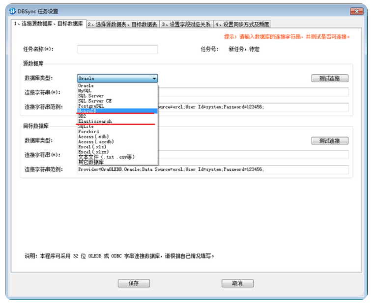
The database synchronization tool dbsync adds support for mongodb and es
Array object sorting
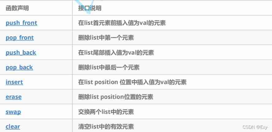
The use of list and Its Simulation Implementation
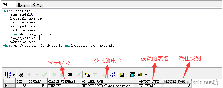
oracle常见锁表处理方式
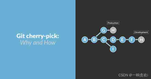
How to use cherry pick?
![[untitled]](/img/c7/b6abe0e13e669278aea0113ca694e0.jpg)
[untitled]
数据库同步工具 DBSync 新增对MongoDB、ES的支持

從色情直播到直播電商
随机推荐
Add a self incrementing sequence number to the antd table component
[C #] the solution of WinForm operation zoom (blur)
网络协议 概念
数据库同步工具 DBSync 新增对MongoDB、ES的支持
创意信息获2家机构调研:GreatDB 数据库已在9地部署
Input type= "password" how to solve the problem of password automatically brought in
Compile QT project script with qmake
自律,提升自制力原来也有方法
Creative information was surveyed by 2 institutions: greatdb database has been deployed in 9 places
Rolling puddle Uni_ App (VIII)
[untitled]
关于测试人生的一站式发展建议
2021-05-21
Debezium同步之Debezium架构详解
JS add spaces to the string
Wallhaven壁纸桌面版
高考作文,高频提及科技那些事儿……
Socket socket programming
2021-04-23
Table replication in PostgreSQL