当前位置:网站首页>Drive HC based on de2115 development board_ SR04 ultrasonic ranging module [source code attached]
Drive HC based on de2115 development board_ SR04 ultrasonic ranging module [source code attached]
2022-07-07 11:15:00 【Lime Miya】
Catalog
1. Experimental platform and purpose
DE2-E115 FPGA Development board + Quartus + Modelsim
Learn and master HC_SR04 Use of modules
2. The experimental requirements
Use DE2 Development board driver HC_SR04 modular , And display the measured data to the nixie tube on the development board .
3. Experimental principle
3.1. Theoretical principles
Ultrasonic principle :
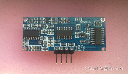
HC-SR04 Ultrasonic ranging module can provide 2cm-400cm Non contact distance sensing function of , Ranging accuracy can be as high as 3mm; The module includes an ultrasonic transmitter 、 Receiver and control circuit . chart 1 by HC-SR04 appearance , Its basic working principle is that after giving the trigger signal to the ultrasonic ranging module, the module emits ultrasonic , When an ultrasonic wave is projected onto an object and reflected back , The module outputs the echo signal , Based on the time difference between trigger signal and echo signal , To determine the distance of the object .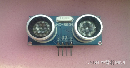
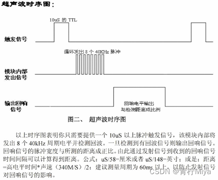
3.2. Hardware module sequence diagram
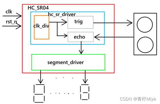
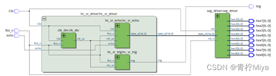
4. System architecture design
5. The module specification
The nixie tube display driver has been done before , No more details here .
5.1. hc_sr_driver Port signal list
| Signal name | Port type | Port bit width | Functional specifications |
|---|---|---|---|
| Clk | I | 1 | The system clock ,50MHz |
| Rst_n | I | 1 | System reset , Low efficiency |
| echo | I | 1 | Ultrasonic module echo signal , High level duration /2 That is, the test distance |
| trig | O | 1 | The ultrasonic module triggers the test signal |
| data_o | O | 19 | Measured distance , In centimeters , Keep three decimal places |
5.2. State transition diagram
This design does not involve state machine .
5.3. Sequence diagram
See Chapter 2.2
5.4. Design documents
/*================================================*\ Filename ﹕ Author ﹕ Description ﹕ The production period is 1us The clock signal of  Called by ﹕ Revision History ﹕ mm/dd/202x Revision 1.0 Email﹕ Company﹕ \*================================================*/
module 	clk_div(
	input  wire			Clk		, //system clock 50MHz
	input  wire 		Rst_n	, //reset ,low valid

	output wire  		clk_us 	  //
);
//Parameter Declarations
	parameter CNT_MAX = 19'd50;//1us The count value of is  50 * Tclk(20ns)

//Interrnal wire/reg declarations
	reg		[5:00]	cnt		; //Counter
	wire			add_cnt ; //Counter Enable
	wire			end_cnt ; //Counter Reset

//Logic Description

	always @(posedge Clk or negedge Rst_n)begin
		if(!Rst_n)begin
			cnt <= 'd0;
		end
		else if(add_cnt)begin
			if(end_cnt)begin
				cnt <= 'd0;
			end
			else begin
				cnt <= cnt + 1'b1;
			end
		end
		else begin
			cnt <= cnt;
		end
	end

	assign add_cnt = 1'b1;
	assign end_cnt = add_cnt && cnt >= CNT_MAX - 19'd1;

	assign clk_us = end_cnt;


endmodule
/*================================================*\ Filename ﹕ Author ﹕ Description ﹕ Ultrasonic trigger ranging module   Waveform period 300ms, front 10us High level  Called by ﹕ Revision History ﹕ mm/dd/202x Revision 1.0 Email﹕ Company﹕ \*================================================*/
module 	hc_sr_trig(
	input  wire			clk_us	, //system clock 1MHz
	input  wire 		Rst_n	, //reset ,low valid

	output wire  		trig	  // Trigger ranging signal
);
//Parameter Declarations
	parameter CYCLE_MAX = 19'd300_000;

//Interrnal wire/reg declarations
	reg		[18:00]	cnt		; //Counter
	wire			add_cnt ; //Counter Enable
	wire			end_cnt ; //Counter Reset

//Logic Description

	always @(posedge clk_us or negedge Rst_n)begin
		if(!Rst_n)begin
			cnt <= 'd0;
		end
		else if(add_cnt)begin
			if(end_cnt)begin
				cnt <= 'd0;
			end
			else begin
				cnt <= cnt + 1'b1;
			end
		end
		else begin
			cnt <= cnt;
		end
	end

	assign add_cnt = 1'b1;
	assign end_cnt = add_cnt && cnt >= CYCLE_MAX - 9'd1;

	assign trig = cnt < 15 ? 1'b1 : 1'b0;

endmodule
/*================================================*\ Filename ﹕ Author ﹕ Description ﹕ Ultrasonic detection distance module   The theoretical test distance of this module  2cm~510cm  The output result shall be kept to two decimal places  Called by ﹕ Revision History ﹕ mm/dd/202x Revision 1.0 Email﹕ Company﹕ \*================================================*/
module 	hc_sr_echo(
	input  wire 		Clk		, //clock 50MHz
	input  wire			clk_us	, //system clock 1MHz
	input  wire 		Rst_n	, //reset ,low valid

	input  wire 		echo	, //
	output wire [18:00]	data_o	  // Detection distance , Retain 3 Decimal place ,*1000 Realization
);
/* S(um) = 17 * t --> x.abc cm */
//Parameter Declarations
	parameter T_MAX = 16'd60_000;//510cm  Corresponding to the count value

//Interrnal wire/reg declarations
	reg				r1_echo,r2_echo; // Edge detection
	wire			echo_pos,echo_neg; //

	reg		[15:00]	cnt		; //Counter
	wire			add_cnt ; //Counter Enable
	wire			end_cnt ; //Counter Reset

	reg		[18:00]	data_r	;
//Logic Description
	// If you use clk_us  Detection edge , Time delay 2us, The difference is too big
	always @(posedge Clk or negedge Rst_n)begin
		if(!Rst_n)begin
			r1_echo <= 1'b0;
			r2_echo <= 1'b0;
		end
		else begin
			r1_echo <= echo;
			r2_echo <= r1_echo;
		end
	end

	assign echo_pos = r1_echo & ~r2_echo;
	assign echo_neg = ~r1_echo & r2_echo;


	always @(posedge clk_us or negedge Rst_n)begin
		if(!Rst_n)begin
			cnt <= 'd0;
		end
		else if(add_cnt)begin
			if(end_cnt)begin
				cnt <= cnt;
			end
			else begin
				cnt <= cnt + 1'b1;
			end
		end
		else begin  //echo  Low level   Zeroing
			cnt <= 'd0;
		end
	end

	assign add_cnt = echo;
	assign end_cnt = add_cnt && cnt >= T_MAX - 1; // Beyond the maximum measurement range, it remains unchanged , limit

	always @(posedge Clk or negedge Rst_n)begin
		if(!Rst_n)begin
			data_r <= 'd2;
		end
		else if(echo_neg)begin
			data_r <= (cnt << 4) + cnt;
		end
		else begin
			data_r <= data_r;
		end
	end //always end

	assign data_o = data_r >> 1;

endmodule
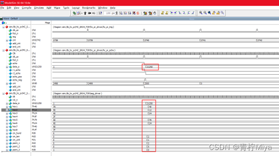
6. The simulation test
/*================================================*\ Filename ﹕tb_hc_sr.v Author ﹕Adolph Description ﹕ Ultrasonic drive test file  Called by ﹕ Revision History ﹕ mm/dd/202x Revision 1.0 Email﹕ Company﹕ \*================================================*/
`timescale 1ns/1ns 		// Simulation system time scale definition

`define clk_period 20  	// Clock cycle parameter definition

module tb_hc_sr();
// Excitation signal definition
	reg				Clk		;
	reg				Rst_n	;
	reg				echo; //

// Response signal definition
	wire	 		trig	;

	wire	[6:0]	hex1	;
	wire	[6:0]	hex2	;
	wire	[6:0]	hex3	;
	wire	[6:0]	hex4	;
	wire	[6:0]	hex5	;
	wire	[6:0]	hex6	;
	wire	[6:0]	hex7	;
	wire	[6:0]	hex8	;
// Instantiation
	HC_SR04_TOP		HC_SR04_TOP(
		/*input */.Clk		(Clk		), //system clock 50MHz
		/*input */.Rst_n	(Rst_n		), //reset ,low valid

		/*input */.echo		(echo		), //
		/*output */.trig		(trig		), // Trigger ranging signal

		/*output [6:0] */.hex1		(hex1		), // - Co anode , Low level active
		/*output [6:0] */.hex2		(hex2		), // -
		/*output [6:0] */.hex3		(hex3		), // -
		/*output [6:0] */.hex4		(hex4		), // Connector
		/*output [6:0] */.hex5		(hex5		), //cm -
		/*output [6:0] */.hex6		(hex6		), //cm -
		/*output [6:0] */.hex7		(hex7		), //cm -
		/*output [6:0] */.hex8		(hex8		)  // Extinguish
	);

// Make a clock
	initial Clk = 1'b0;
	always #(`clk_period / 2) Clk = ~Clk;

// Generate incentives
	initial  begin
		Rst_n = 1'b0;
		echo  = 1'b0;
		#(`clk_period * 20 + 3);
		Rst_n = 1'b1;
		#(`clk_period * 20);

		wait(HC_SR04_TOP.hc_sr_driver.hc_sr_trig.cnt == 240);
		echo = 1'b1;// Test the completion of ultrasonic signal transmission ,echo pull up

		#(50 * `clk_period * 2500 + 7);
		echo = 1'b0;

		#(`clk_period * 200);
		$stop(2);
	end

endmodule
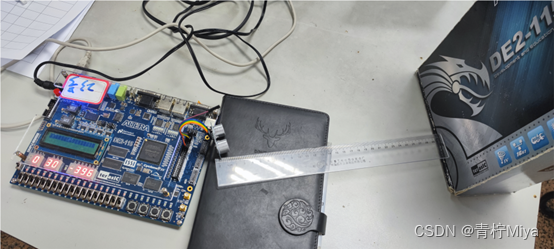
7. Board level verification and debugging
8. summary
It has been tested , The measured distance is consistent with the actual distance , The module function is basically realized .
however , This design can only test 4~249cm Range distance , It should be in design echo Module problem , Leave it to be solved later , The nixie tube driver used is 8 position 7 Segment nixie tube , It involves the use of functions , If you haven't touched , You can taste one or two .
The purpose of posting code is only to facilitate understanding , If become CV warrior , The meaning of learning is lost , I hope you can gain something .
边栏推荐
猜你喜欢

Web端自动化测试失败的原因
关于SIoU《SIoU Loss: More Powerful Learning for Bounding Box Regression Zhora Gevorgyan 》的一些看法及代码实现
![[untitled]](/img/f9/18b85ad17d4c560f2b9d95a53ee72a.jpg)
[untitled]
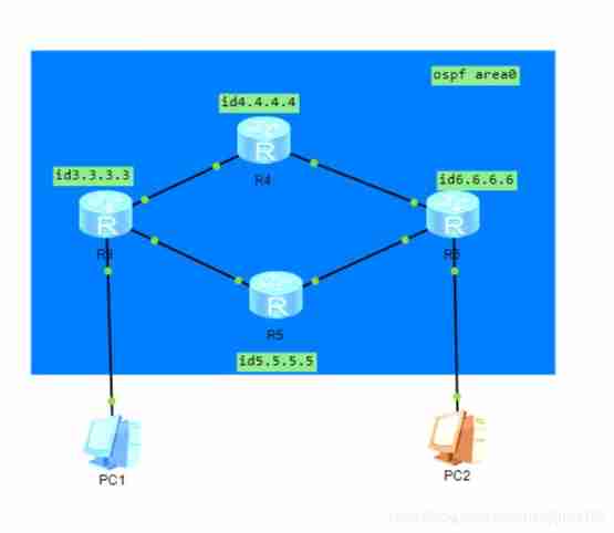
Using ENSP to do MPLS pseudo wire test
在我有限的软件测试经历里,一段专职的自动化测试经验总结
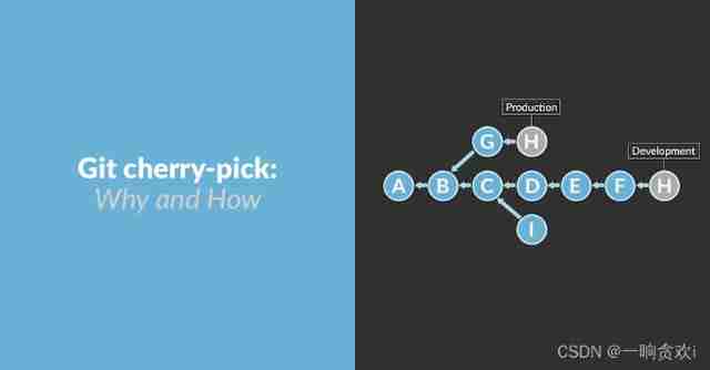
How to use cherry pick?
Array object sorting

技术分享 | 抓包分析 TCP 协议
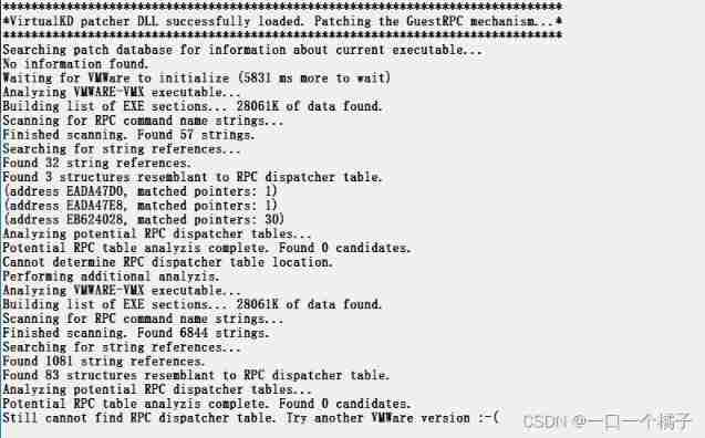
Still cannot find RPC dispatcher table failed to connect in virtual KD
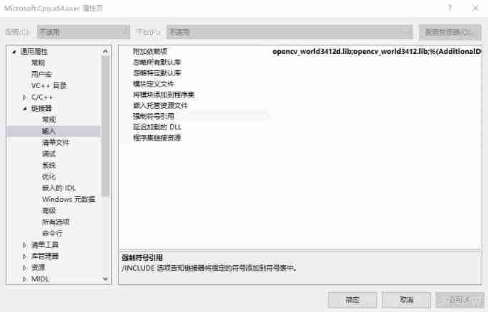
Opencv installation and environment configuration - vs2017
随机推荐
July 10, 2022 "five heart public welfare" activity notice + registration entry (two-dimensional code)
请问申购新股哪个证券公司开户是最好最安全的
"Dream Cup" 2017 Jiangsu information and future primary school summer camp it expert PK program design questions
The seventh training assignment
数据库同步工具 DBSync 新增对MongoDB、ES的支持
网络协议 概念
PostgreSQL中的表复制
[untitled]
Go Slice 比较
测试优惠券要怎么写测试用例?
Deep understanding of Apache Hudi asynchronous indexing mechanism
Compile QT project script with qmake
基于STC8G1K08的0.96寸IIC液晶屏驱动程序
Unity determines whether the mouse clicks on the UI
[untitled]
Bookmarking - common website navigation for programmers
verilog设计抢答器【附源码】
变量的解构赋值
[untitled]
Go redis Middleware