当前位置:网站首页>Blackfly s usb3 industrial camera: buffer processing
Blackfly s usb3 industrial camera: buffer processing
2022-07-07 02:00:00 【The moon shines on the silver sea like a dragon】
Blackfly S USB3 Industrial camera : Buffer processing
The technical content of this blog can be applied to FLIR Network interface and USB3 The camera
Flir Blackfly S USB3 Product introduction
Blackfly S Adopt the advanced ice shape sensor in the industry .
It's powerful , You can easily generate the exact image you need , And accelerate application development .
Including automatic and precise manual control of image capture and camera preprocessing .
Blackfly S Provide GigE、USB3、 Suit and board versions .
Accurate image SONY CMOS Choices among sensors include : Global shutter 、 Polarization and high sensitivity BSI sensor .
The following mainly explains the essence and working mode of buffer and buffer processing mode , And provide an example of the expected effect of the captured image
Camera buffer introduction
After the image is taken by the camera , Automatically transferred to PC And stored in RAM in .
The space allocated in memory for storing images is called buffer .
The number of buffers depends on the maximum frame rate of the camera , Memory is automatically allocated by default .
The number of buffers associated with the camera can be changed by switching the stream buffer count mode from automatic to manual and assigning a value to the manual stream buffer count at the same time .
The maximum number of buffers depends on RAM Available memory for , The size of each buffer depends on the image size .
Spinnaker 1.13 And later versions have the function of automatic buffer counting mode . Previous versions set the number of buffers to 10.
When using images , You can only interact with images after they are retrieved from the buffer . This type of interaction includes displaying images on the screen 、 Save to disk or apply image processing .
Buffer processing
Buffer processing determines what is available for each camera Number of buffers ( If you can cover ) as well as The order in which images are retrieved .
Buffer processing mode
Spinnaker There are four types of buffer processing :
1、 First deal with the latest :
The application processes the image at the end of the output buffer queue ( The latest one available )
This method is better for applications such as motion prediction, which need to always obtain the latest frame, but the previous frame can also add valuable information .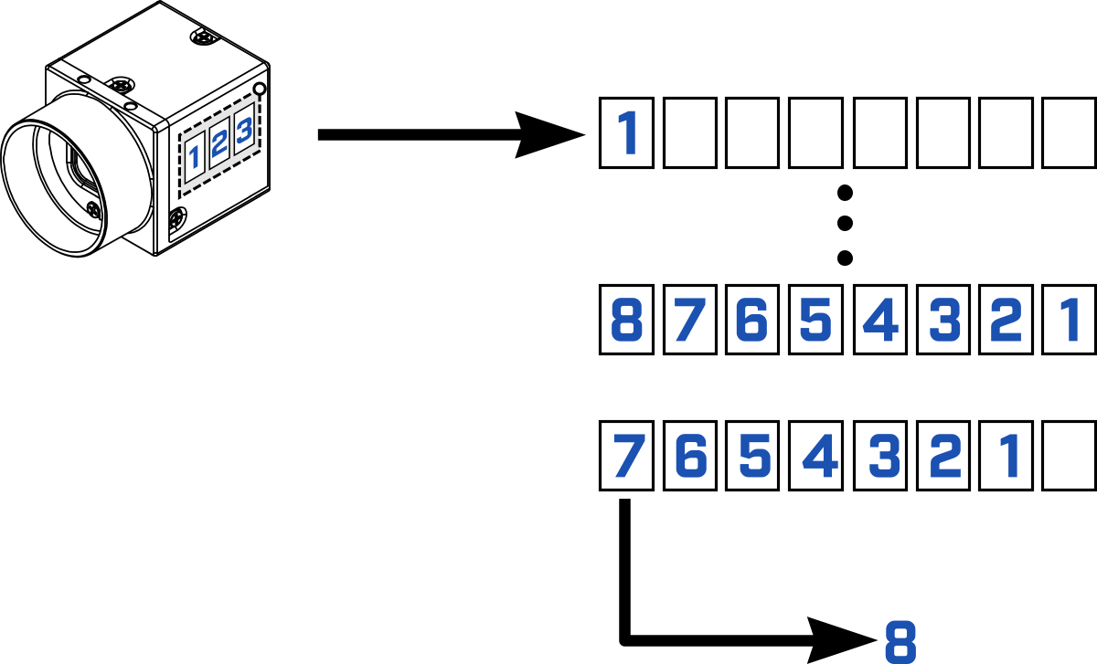
2、 Only the latest :
Applications always process recently completed images ( The latest one ). Discard the previous image . Stream buffer count ignored . This mode is usually used for real-time display GUI, It requires that there is no delay between the camera and the display .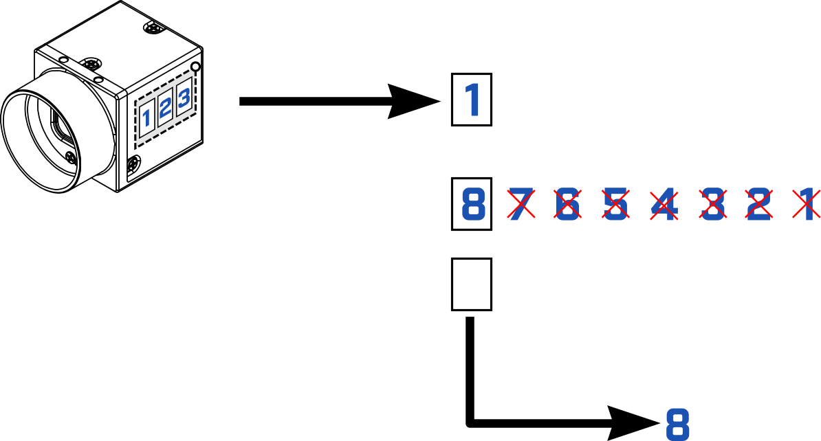
3、 First deal with the earliest :
The application always processes the first image of the output buffer queue ( The first one available )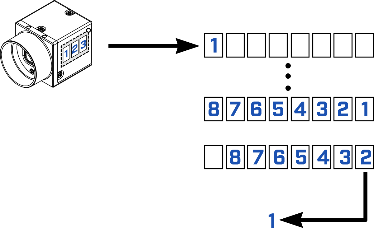
4、 First write the earliest :
The application always processes the first image of the output buffer queue ( The earliest available ). If a new image is imported , It overwrites the buffer from the beginning of the queue . It looks like a circular buffer .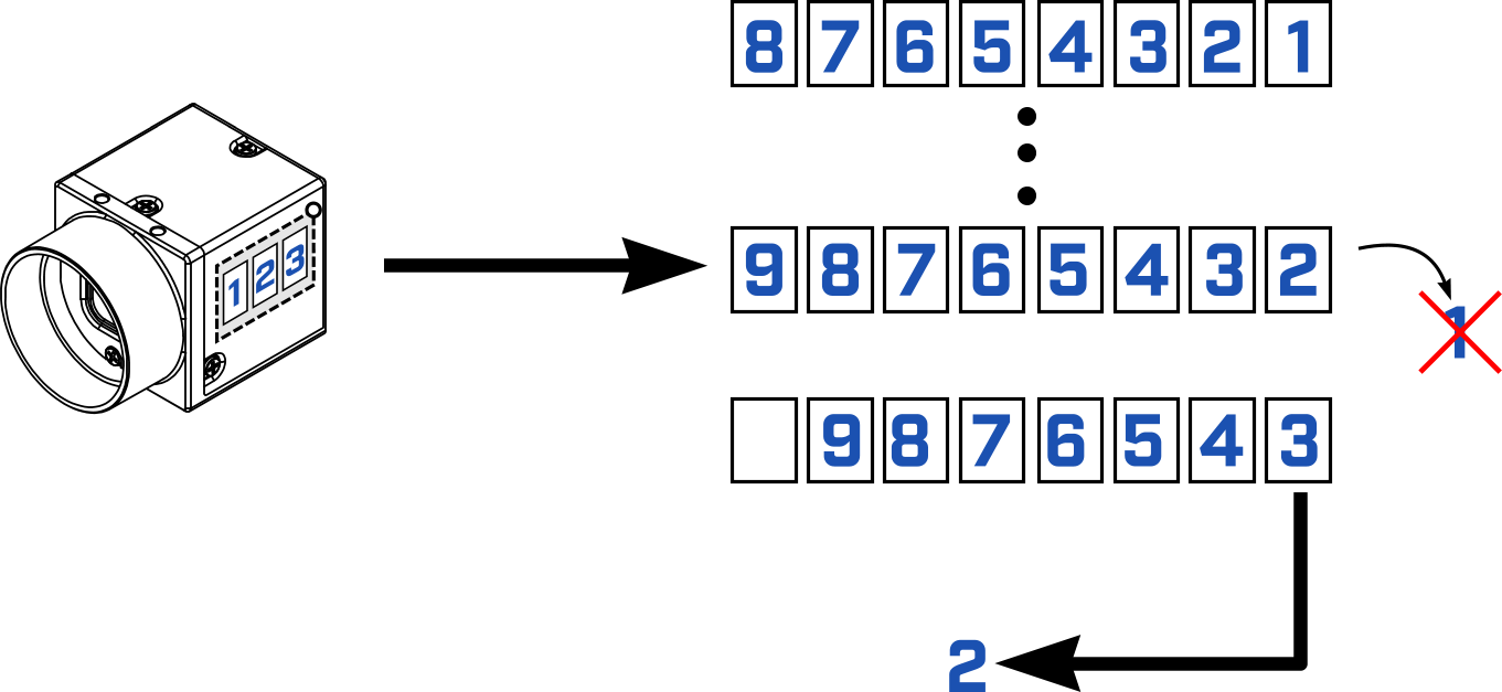
Example of buffer processing mode
The above explanation is still quite abstract , Here are a few examples to make it clear
Example 1
Trigger the camera 6 Time . After each trigger , We will retrieve the image , Then the output FrameID(Frame ID Always from 0 Start ).
Example condition :
- 1 FPS
- No image processing
- There is no change in the number of buffers or buffer processing mode
Sample results : - 0、1、2、3、4、5
No matter which buffer processing mode is used , The results should all be the same . however , If the camera triggers faster than the processing power of the host , Or if there is a delay on the host , Then the image will be discarded . In this case , The output frame ID It may not match the results shown above Again , When the image retrieval position is different from its transmission position , The buffer processing mode will determine the retrieved images and the order of images .
Example 2
Trigger the camera 6 Time . After the sixth trigger , We start to retrieve three images , Then the output FrameID.
Example condition :
- 1 FPS
- No image processing
- Set the number of buffers to 3(PC Only in memory 3 Zhang image )
- Apply each buffer processing mode one by one
First deal with the latest :
- 2、1、0
- Not covered , The camera retains the first three images , discarded 3、4、5 frame
Only the latest :
- 5、 error
- The camera retains the latest image , But when trying to retrieve an image that does not exist , There was a mistake
First deal with the earliest :
- and “ First deal with the latest ” equally , The difference is that the earliest image is retrieved first
First write the earliest :
- 3、4、5
- frame 0、1 and 2 Covered , Representation frame 3 It is the earliest image and the first to be retrieved , Then retrieve the frame 4 and 5
Transmission queue ( Camera onboard image buffer )
Each camera has an onboard image buffer , Each captured image passes through the buffer . As long as the camera remains powered , It can also be used to store images indefinitely . The image buffer can store multiple images .
Blackfly S The camera has 240 MB Image buffer of .
The space occupied by each image is four times the maximum resolution of the camera . for example ,BFS-U3-13Y3C The resolution of the camera is 1.3 MP, Then each image will occupy the image buffer 5.2 MB Space . The maximum number of images that can be stored is shown in TransferQueueMaxBlockCount node . The number of images currently buffered on the camera is shown in TransferQueueCurrentBlockCount node .
If USB3 After the camera takes images PC There is no buffer available on , Then the image will be automatically stored in the onboard buffer . once PC There's space available , The images in the camera's onboard buffer will be automatically transferred to PC. If you are using “ First deal with the latest ” Pattern , This situation will interfere with the expected image sequence .
adopt Code Change buffer size
adopt Spinnaker C++ Interface Change the buffer size to 11, The default is 10
Spinnaker::GenApi::INodeMap & sNodeMap = cam->GetTLStreamNodeMap();
CIntegerPtr StreamNode = sNodeMap.GetNode(“StreamDefaultBufferCount”);
INT64 bufferCount = StreamNode->GetValue();
StreamNode->SetValue(11);
adopt GetTLStreamNodeMap get NodeMap
adopt GetNode get Node
adopt GetValue Default buffer size
adopt SetValue Set the buffer size to 11
边栏推荐
- 一片葉子兩三萬?植物消費爆火背後的“陽謀”
- Correct use of BigDecimal
- C language [23] classic interview questions [Part 2]
- ROS学习(25)rviz plugin插件
- JS ES5也可以創建常量?
- Unicode string converted to Chinese character decodeunicode utils (tool class II)
- Appium自动化测试基础 — uiautomatorviewer定位工具
- 鼠标右键 自定义
- 蓝桥杯2022年第十三届省赛真题-积木画
- Cisp-pte practice explanation (II)
猜你喜欢

百度飞将BMN时序动作定位框架 | 数据准备与训练指南 (上)
新工作感悟~辞旧迎新~
Basic introduction and use of dvajs
ROS learning (21) robot slam function package -- installation and testing of orbslam

Set WordPress pseudo static connection (no pagoda)

How did partydao turn a tweet into a $200million product Dao in one year
mongodb查看表是否导入成功
场景实践:基于函数计算快速搭建Wordpress博客系统
Appium foundation - appium inspector positioning tool (I)

Flir Blackfly S 工业相机:通过外部触发实现多摄像头同步拍摄
随机推荐
开发中对集合里面的数据根据属性进行合并数量时犯的错误
ROS学习(26)动态参数配置
设置Wordpress伪静态连接(无宝塔)
FLIR blackfly s industrial camera: configure multiple cameras for synchronous shooting
The difference between Tansig and logsig. Why does BP like to use Tansig
Threadlocalutils (tool class IV)
454 Baidu Mianjing 1
Cat recycling bin
一片叶子两三万?植物消费爆火背后的“阳谋”
我如何编码8个小时而不会感到疲倦。
Modify the system time of Px4 flight control
Appium automation test foundation uiautomatorviewer positioning tool
Let's see how to realize BP neural network in Matlab toolbox
ROS learning (21) robot slam function package -- installation and testing of orbslam
ROS learning (22) TF transformation
鼠标右键 自定义
AcWing 361. Sightseeing cow problem solution (SPFA seeking positive ring)
Set WordPress pseudo static connection (no pagoda)
Ros Learning (23) Action Communication Mechanism
Cisp-pte practice explanation (II)