Download the latest tutorial :http://www.armbbs.cn/forum.php?mod=viewthread&tid=98429
The first 6 Chapter ThreadX GUIX To start with STM32H7 DMA2D Speed up
This chapter will explain DMA2D Brush color block is often used in application , Brush bitmap ,Alpha The implementation of blending and image blending .
6.1 Important tips for beginners
6.2 DMA2D Drive design
6.3 Make C File format bitmap
6.4 DMA2D Common operations ( important )
6.5 DMA2D Drive migration and use
6.6 Experimental routine design framework
6.7 Experiment routine description
6.8 summary
6.1 Important tips for beginners
- This chapter is for ThreadX GUIX Of LCD DMA2D Speed up preparation .
- DMA2D One of the important concepts in it is line offset , This knowledge must be well understood , See this chapter for details 2.2 Section .
- DMA2D You can draw directly ARGB8888,RGB565 Color format bitmap , And can be convenient to do a variety of transparent effects and mixed image display .
- LCD The acceleration depends on DMA2D, So we must master its usage .
- shielding MDK AC6 Use Chinese GBK Coded warning methods , So that people can continue to use GBK Code Chinese characters :http://www.armbbs.cn/forum.php?mod=viewthread&tid=98670 .
6.2 DMA2D Drive design
6.2.1 DMA2D Driving design ideas
DMA2D The design of the driver is easier :
- The user simply calls the function __HAL_RCC_DMA2D_CLK_ENABLE Can make DMA2D You can use .
- Default DMA2D Of API They're all blocking , This way is using RTOS It's more convenient , Users can GUI The priority of the task is set only higher than that of the idle task , There are high priority tasks to perform , Can switch to high priority tasks in time ,GUI Mission waiting DMA2D The execution is complete . So as to make full use of DMA2D and CPU, To maximize the performance of the chip .
- The most important one , be-all DMA2D operation , Directly using register mode , No longer use HAL Kuo gave it to me API, To maximize performance .
6.2.2 The meaning of line offset ( important )
understand DMA2D The key to transmission is to understand line offsets . Foreground layer , Both the background layer and the output area have a row offset register , For your convenience , Here's a block diagram :
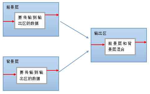
Conditions :
- Foreground layer , The resolution of both the background layer and the output area is 800*480 The resolution of the , The color format is RGB565.
- Set the starting coordinates in the foreground layer (40,30), Long 480, high 272 The data of and the starting coordinate in the background layer (50,40), Long 480, high 272 Copy the data to the starting address of the output area (60,50), Long 480, high 272 Region .
elicit questions :
So here comes the question , The starting coordinates of foreground layer and background layer are easy to calculate at the starting position of respective data buffer . For example, the foreground layer is the first address of the foreground layer plus 30*800*2 + 40*2, multiply 2 The reason is that RGB565 Color format 1 Pixels take up two bytes .
The difficulty is how to ensure that the foreground layer is copied 480 The length of the data after , How to switch to the next line . This is the time , Line offsets come in handy , Line offset means the distance from the end of one line to the beginning of the next , Number of pixels per unit ( That is the total length of the two red arrows in the diagram above ). Offset through this line , We can copy it from the front view 480*272 The data of .
Empathy , The line offset of background layer and output area is also the same meaning .
6.3 Make C File format bitmap
because DMA2D Refresh the image using , So this section introduces the production of bitmap for you .
6.3.1 What is a bitmap
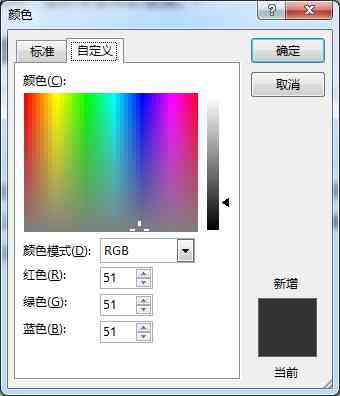
Bitmap (bitmap), It's also called a dot matrix , It's using an array of pixels to represent an image . Each pixel in a bitmap has its own color value , These color values are determined by RGB Combination or gray value to represent . among ,RGB It means Red Red ,Green Green and Blue Blue , Any color can be made up of these three colors . Computer graphics software basically has a custom color function , It's a good illustration RGB The role of the three primary colors :
According to bit depth , You can divide a bitmap into 1 position ( monochrome ),2 position (4 color ,CGA),4 position (16 color ,VGA),8 position (256 color ),16 position ( Enhance color ),24 position ( True color ) and 32 I'm waiting for you .
About bitmaps , Another concept is alpha passageway . So-called alpha Channel refers to the original image coding method based on , Increase the transparency of pixels . Graphics processing , Usually put RGB The three color information is called the red channel 、 Green channel and blue channel , Accordingly, transparency is called Alpha passageway .
6.3.2 Icon download
Here is a recommended icon download website for you :http://www.easyicon.net/ , This website is very easy to use , What icon is needed to retrieve keywords directly . Here is the keyword cartoon Search , Finally choose the address :
https://www.easyicon.net/581941-Lufy_cartoon_icon.html The icon inside , We download 128*128 Dot matrix size PNG picture ( The downloaded images have been placed in the supporting examples of this chapter Doc In the folder ):

Let's go in two steps , Convert them into ARGB8888 Format bitmap and RGB565 Format bitmap .
6.3.3 transformation PNG Picture is ARGB8888 Format bitmap
- Download Small Software BmpCvt:http://www.armbbs.cn/forum.php?mod=viewthread&tid=93478 .
- The first 1 Step : open BmpCvtST.exe , Direct will PNG Drag the format picture into the software , Or click File->Open Loading is also possible .
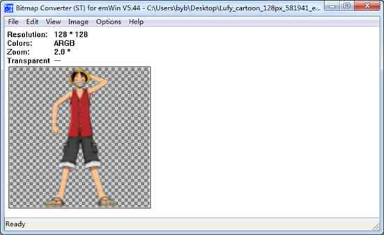
- The first 2 Step : Click on File->Save as, Pop up the following window
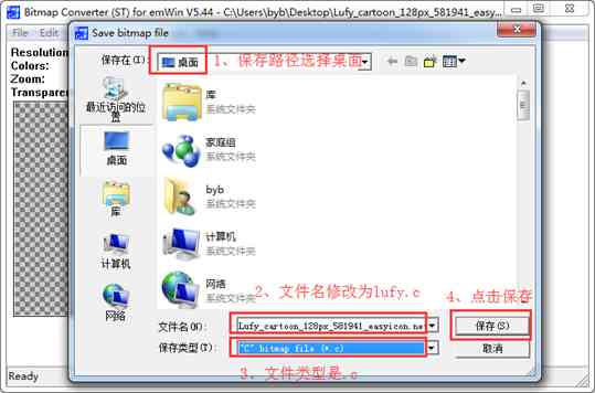
The above screenshot shows a total of 4 Step by step , Among them the first 2 Step 2: change the name because the original name is too long , It is not convenient to call program code .
- The first 3 Step : The first 2 After the step is finished , Pop up the following window :
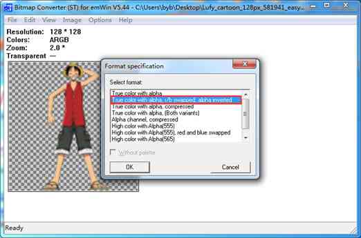
The first 1 Options True color with alpha The color format is ABGR, Our choice here is No 2 individual , This is ARGB Format . Of course , You can also choose ABGR Format , because H7 Of DMA2D You can set Alpha By flipping and R Channel and B Channel interaction location , So as to achieve ABGR To ARGB Format .
Click on OK A new file appears on the desktop after the button , namely lufy.c, It's on the desktop because 2 The path chosen in the step is the desktop .
open lufy.c file , The code is as follows :
/*********************************************************************
*                SEGGER Microcontroller GmbH & Co. KG                *
*        Solutions for real time microcontroller applications        *
*                           www.segger.com                           *
**********************************************************************
*                                                                    *
* C-file generated by                                                *
*                                                                    *
*        Bitmap Converter (ST) for emWin V5.32.                      *
*        Compiled Oct  8 2015, 11:58:22                              *
*                                                                    *
*        (c) 1998 - 2015 Segger Microcontroller GmbH & Co. KG        *
*                                                                    *
**********************************************************************
*                                                                    *
* Source file: pic                                                   *
* Dimensions:  64 * 64                                               *
* NumColors:   16bpp: 65536                                          *
*                                                                    *
**********************************************************************
*/

#include <stdlib.h>

#include "GUI.h"

#ifndef GUI_CONST_STORAGE
  #define GUI_CONST_STORAGE const
#endif

extern GUI_CONST_STORAGE GUI_BITMAP bmlufy;

static GUI_CONST_STORAGE unsigned long _aclufy[] = {
  0x00000000, 0x00000000, 0x00000000, 0x00000000, 0x00000000, 0x00000000, 0x00000000, 0x00000000, 0x00000000, 0x00000000, 0x00000000, 0x00000000, 0x00000000, 0x00000000, 0x00000000, 0x00000000, 0x00000000, 0x00000000, 0x00000000, 0x00000000, 0x00000000,
        0x00000000, 0x00000000, 0x00000000, 0x00000000, 0x00000000, 0x00000000, 0x00000000, 0x00000000, 0x00000000, 0x00000000, 0x00000000, 0x00000000, 0x00000000, 0x00000000, 0x00000000, 0x00000000, 0x00000000, 0x00000000, 0x00000000, 0x00000000,
        0x00000000, 0x00000000, 0x00000000, 0x00000000, 0x00000000, 0x00000000, 0x00000000, 0x00000000, 0x00000000, 0x00000000, 0x00000000, 0x00000000, 0x00000000, 0x00000000, 0x0042454E, 0x00494C4E, 0x00393E50, 0x0046402A, 0x00968C62, 0x093E3C26,
        0x2A787653, 0x597F8266, 0x606F6F4D, 0x5F7D7D54, 0x37747B50, 0x0B455035, 0x00745F3F, 0x00615856, 0x00655751, 0x00000000, 0x00000000, 0x00000000, 0x00000000, 0x00000000, 0x00000000, 0x00000000, 0x00000000, 0x00000000, 0x00000000, 0x00000000,

       /*  The following data is not listed  */

};

GUI_CONST_STORAGE GUI_BITMAP bmlufy = {
  128, // xSize
  128, // ySize
  512, // BytesPerLine
  32, // BitsPerPixel
  (unsigned char *)_aclufy,  // Pointer to picture data
  NULL,  // Pointer to palette
  GUI_DRAW_BMPM8888I
};

/*************************** End of file ****************************/
For generated code, only arrays are required static GUI_CONST_STORAGE unsigned long _aclufy[], This number needs to be modified a little bit , take GUI_CONST_STORAGE It is amended as follows const It can be used in engineering .const Indicates that the array is stored in flash Inside .
6.3.4 transformation PNG Picture is RGB565 Format bitmap
Conversion method and 56.4.1 The bars are similar , There are two main differences :
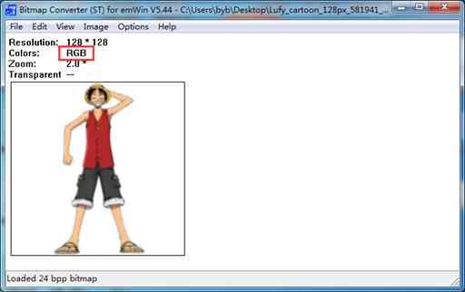
- The first 1 A little different : Use the drawing software on the computer to convert the downloaded icon into BMP Format (PNG The transparent channel in the picture will be filtered out ), Reuse BmpCvt The effect of opening the software is as follows , No more Alpha passageway .
- The first 2 A little different , The conversion format is as follows :
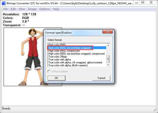
The code generated after the conversion is as follows :
/*********************************************************************
*                SEGGER Microcontroller GmbH & Co. KG                *
*        Solutions for real time microcontroller applications        *
*                           www.segger.com                           *
**********************************************************************
*                                                                    *
* C-file generated by                                                *
*                                                                    *
*        Bitmap Converter (ST) for emWin V5.44.                      *
*        Compiled Nov 10 2017, 08:52:20                              *
*                                                                    *
*        (c) 1998 - 2017 Segger Microcontroller GmbH & Co. KG        *
*                                                                    *
**********************************************************************
*                                                                    *
* Source file: Lufy_cartoon_128px_581941_easyiconnet                 *
* Dimensions:  128 * 128                                             *
* NumColors:   16bpp: 65536                                          *
*                                                                    *
**********************************************************************
*/

#include <stdlib.h>

#include "GUI.h"

#ifndef GUI_CONST_STORAGE
  #define GUI_CONST_STORAGE const
#endif

extern GUI_CONST_STORAGE GUI_BITMAP bmLufy_cartoon_128px_581941_easyiconnet;

static GUI_CONST_STORAGE unsigned short _acLufy_cartoon_128px_581941_easyiconnet[] = {
  0xFFFF, 0xFFFF, 0xFFFF, 0xFFFF, 0xFFFF, 0xFFFF, 0xFFFF, 0xFFFF, 0xFFFF, 0xFFFF, 0xFFFF, 0xFFFF, 0xFFFF, 0xFFFF, 0xFFFF, 0xFFFF, 0xFFFF, 0xFFFF, 0xFFFF, 0xFFFF, 0xFFFF, 0xFFFF, 0xFFFF, 0xFFFF, 0xFFFF, 0xFFFF, 0xFFFF, 0xFFFF, 0xFFFF, 0xFFFF, 0xFFFF,
        0xFFFF, 0xFFFF, 0xFFFF, 0xFFFF, 0xFFFF, 0xFFFF, 0xFFFF, 0xFFFF, 0xFFFF, 0xFFFF, 0xFFFF, 0xFFFF, 0xFFFF, 0xFFFF, 0xFFFF, 0xFFFF, 0xFFFF, 0xFFFF, 0xFFFF, 0xFFFF, 0xFFFF, 0xFFFF, 0xFFFF, 0xFFFF, 0xFFFF, 0xFFFF, 0xFFFF, 0xFFFF, 0xFFFF, 0xF7BE,
        0xE73C, 0xD699, 0xC657, 0xCE77, 0xDF1A, 0xF7BE, 0xFFFF, 0xFFFF, 0xFFFF, 0xFFFF, 0xFFFF, 0xFFFF, 0xFFFF, 0xFFFF, 0xFFFF, 0xFFFF, 0xFFFF, 0xFFFF, 0xFFFF, 0xFFFF, 0xFFFF, 0xFFFF, 0xFFFF, 0xFFFF, 0xFFFF, 0xFFFF, 0xFFFF, 0xFFFF, 0xFFFF, 0xFFFF,
        0xFFFF, 0xFFFF, 0xFFFF, 0xFFFF, 0xFFFF, 0xFFFF, 0xFFFF, 0xFFFF, 0xFFFF, 0xFFFF, 0xFFFF, 0xFFFF, 0xFFFF, 0xFFFF, 0xFFFF, 0xFFFF, 0xFFFF, 0xFFFF, 0xFFFF, 0xFFFF, 0xFFFF, 0xFFFF, 0xFFFF, 0xFFFF, 0xFFFF, 0xFFFF, 0xFFFF, 0xFFFF, 0xFFFF, 0xFFFF,
        0xFFFF, 0xFFFF, 0xFFFF, 0xFFFF, 0xFFFF, 0xFFFF, 0xFFFF,

       /*  The following data is not listed  */

};

GUI_CONST_STORAGE GUI_BITMAP bmlufy = {
  128, // xSize
  128, // ySize
  256, // BytesPerLine
  16, // BitsPerPixel
  (unsigned char *) aclufy,  // Pointer to picture data
  NULL,  // Pointer to palette
  GUI_DRAW_BMPM565
};

/*************************** End of file ****************************/
The code generated here also requires only arrays static GUI_CONST_STORAGE unsigned long _aclufy[], And will GUI_CONST_STORAGE It is amended as follows const It can be used in engineering .
6.4 DMA2D Common operations ( important )
DMA2D Common use of API Be proficient in , hinder GUI The underlying driver acceleration of ,JPEG Hard solution , The camera and other parts need to be used . Here for you to introduce the following several commonly used API:
- _DMA2D_Fill
- _DMA2D_Copy
- _DMA2D_MixColorsBulk
- _DMA2D_AlphaBlendingBulk
- _DMA2D_DrawAlphaBitmap
6.4.1 function _DMA2D_Fill
The function prototype :
1.    /*
2.    ******************************************************************************************************
3.    *     Letter   Count   name : _DMA2D_Fill
4.    *     Functional specifications : DMA2D Color fill function
5.    *     shape      ginseng : pDst           Color data destination address
6.    *             xSize          Color block X Axis size , That is, pixels per row
7.    *             ySize          Color block Y Axis size , That is, the number of lines
8.    *             OffLine        Line offset of foreground image
9.    *             ColorIndex     Color block color value
10.    *             PixelFormat    Target area color format
11.    *     return   return   value :  nothing
12.    ******************************************************************************************************
13.    */
14.    static void _DMA2D_Fill(void * pDst,
15.                            uint32_t xSize,
16.                            uint32_t ySize,
17.                            uint32_t OffLine,
18.                            uint32_t ColorIndex,
19.                            uint32_t PixelFormat)
20.    {
21.
22.        /* DMA2D Using register to memory mode ,  This pattern does not work for foreground and background layers  */
23.        DMA2D->CR      = 0x00030000UL | (1 << 9);
24.        DMA2D->OCOLR   = ColorIndex;
25.        DMA2D->OMAR    = (uint32_t)pDst;
26.        DMA2D->OOR     = OffLine;
27.        DMA2D->OPFCCR  = PixelFormat;
28.        DMA2D->NLR     = (uint32_t)(xSize << 16) | (uint16_t)ySize;
29.
30.        /*  Start transmission  */
31.        DMA2D->CR   |= DMA2D_CR_START;
32.
33.        /*  wait for DMA2D Transmission complete  */
34.        while (DMA2D->CR & DMA2D_CR_START) {}
35.    }
Function description :
This function is mainly used for LCD Color fill .
- The first 23 That's ok , Set up DMA2D Register to memory data transmission mode , namely DMA2D take OCOLR Register sets the color value to fill in the memory .
- The first 24 That's ok ,OCOLR Register is used to set the output color value , Pay special attention to the following 27 The output color format of the row matches . For example, the setting is RGB565, Then set the color value as 16 Position color .
- The first 25 That's ok , Set the first address of the output fill area .
- The first 26 That's ok , Set the output line offset .
- The first 27 That's ok , Set output color format , If it's output to LCD memory , Then this format should be consistent with LCD Color format is consistent , Otherwise, the display is abnormal .
- The first 28 That's ok , high 16 Bits are used to set the number of pixels per row , low 16 Bits are used to set the number of rows , Combined to determine the total number of transfers .
- The first 31-34 That's ok , Start transmission , And wait for the transmission to complete .
matters needing attention :
- It is necessary to call the function before using this function __HAL_RCC_DMA2D_CLK_ENABLE Can make DMA2D The clock .
Use examples :
The starting coordinates (24, 20), Output color format RGB565, Draw a 128x128 The red filling area of :
1.        _DMA2D_Fill((void *)(SDRAM_LCD_BUF1 + g_LcdWidth*20*2 + 24*2),  /*  Show start address (24, 20) */
2.                      128,                                               /*  The color block is long  */
3.                    128,                                               /*  The color block is high  */
4.                    g_LcdWidth-128,                                    /*  Color block row offset  */
5.                    CL_RED,                                            /*  Color block color  */
6.                    LTDC_PIXEL_FORMAT_RGB565);                         /*  Color block color format  */
- The first 1 That's ok , According to the set starting coordinates , The starting coordinates of the calculation are in LCD A specific location in video memory .
SDRAM_LCD_BUF1 Express LCD First memory address .
g_LcdWidth*20*2 It calculates the number of bytes occupied by the number of rows .
24*2 The specific address of the line is calculated .
multiply 2 Because RGB565 Color format 1 Pixels take up two bytes .
- The first 4 That's ok , Output line offset means the distance from the end of one line to the beginning of the next , Number of pixels per unit . Because the length of the filling area is 128, So the line offset is LCD Length minus 128.
6.4.2 function _DMA2D_Copy
The function prototype :
1.    /*
2.    ******************************************************************************************************
3.    *     Letter   Count   name : _DMA2D_Copy
4.    *     Functional specifications :  adopt DMA2D Copy the color data of the specified area from the front scene layer to the target area
5.    *     shape      ginseng : pSrc          Color data source address
6.    *             pDst           Color data destination address
7.    *             xSize          Of the destination area X Axis size , That is, pixels per row
8.    *             ySize          Of the destination area Y Axis size , That is, the number of lines
9.    *             OffLineSrc     Line offset of foreground image
10.    *             OffLineDst     Line offset of output
11.    *             PixelFormat    Target area color format
12.    *     return   return   value :  nothing
13.    ******************************************************************************************************
14.    */
15.    static void _DMA2D_Copy(void * pSrc,
16.                            void * pDst,
17.                            uint32_t xSize,
18.                            uint32_t ySize,
19.                            uint32_t OffLineSrc,
20.                            uint32_t OffLineDst,
21.                            uint32_t PixelFormat)
22.    {
23.
24.        /* DMA2D Using memory to memory mode ,  This pattern is the foreground layer as DMA2D Input  */
25.        DMA2D->CR      = 0x00000000UL | (1 << 9);
26.        DMA2D->FGMAR   = (uint32_t)pSrc;
27.        DMA2D->OMAR    = (uint32_t)pDst;
28.        DMA2D->FGOR    = OffLineSrc;
29.        DMA2D->OOR     = OffLineDst;
30.
31.        /*  Both foreground layer and output area use RGB565 Color format  */
32.        DMA2D->FGPFCCR = LTDC_PIXEL_FORMAT_RGB565;
33.        DMA2D->OPFCCR  = LTDC_PIXEL_FORMAT_RGB565;
34.
35.        DMA2D->NLR     = (uint32_t)(xSize << 16) | (uint16_t)ySize;
36.
37.        /*  Start transmission  */
38.        DMA2D->CR   |= DMA2D_CR_START;
39.
40.        /*  wait for DMA2D Transmission complete  */
41.        while (DMA2D->CR & DMA2D_CR_START) {}
42.    }
Function description :
This function is used to copy the color data of the specified area from the front scene layer to the target area .
- The first 25 That's ok , Set up DMA2D Data mode is transmitted to memory by using memory , Input memory can only be foreground layer . namely DMA2D take FGMAR The stored data pointed to by the register is transferred to the register OMAR The memory pointed to .
- The first 26 That's ok , Set the first address of foreground layer data .
- The first 27 That's ok , Set the first address of output memory .
- The first 28 That's ok , Set foreground layer row offset .
- The first 29 That's ok , Set the output area line offset .
- The first 32-33 That's ok , Set foreground layer and output area with RGB565 Color format . Also note , If it's output to LCD memory , Then the output color format should be consistent with LCD Color format is consistent , Otherwise, the display is abnormal .
- The first 35 That's ok , high 16 Bits are used to set the number of pixels per row , low 16 Bits are used to set the number of rows , Combined to determine the total number of transfers .
- The first 38-41 That's ok , Start transmission , And wait for the transmission to complete .
matters needing attention :
- It is necessary to call the function before using this function __HAL_RCC_DMA2D_CLK_ENABLE Can make DMA2D The clock .
Use examples :
Will be the size 128*128, The color format is RGB565 Draw a bitmap to LCD The starting coordinates are (328, 20) Region , The output color format is also configured as RGB565.
1.        _DMA2D_Copy((uint32_t *)_acmickey,                                      /*  Bitmap address  */
2.                    (uint32_t *)(SDRAM_LCD_BUF1 + g_LcdWidth*20*2 + 328*2),     /*  Show start address (328, 20) */
3.                    128,                                                      /*  The bitmap is long  */
4.                    128,                                                      /*  Bitmap height  */
5.                    0,                                                        /*  Bitmap row offset  */
6.                    g_LcdWidth-128,                                           /*  Row offset of target area  */
7.                    LTDC_PIXEL_FORMAT_RGB565);                               /*  Target area color format  */
- The first 1 Line is the first address of the bitmap .
- The first 2 That's ok , According to the set starting coordinates , The starting coordinates of the calculation are in LCD A specific location in video memory .
SDRAM_LCD_BUF1 Express LCD First memory address .
g_LcdWidth*20*2 It calculates the number of bytes occupied by the number of rows .
328*2 The specific address of the line is calculated .
multiply 2 Because RGB565 Color format 1 Pixels take up two bytes .
- The first 5 Line is the line offset of the bitmap , Line offset means the distance from the end of one line to the beginning of the next , Number of pixels per unit . Because the whole bitmap has to be drawn , All line offsets are 0.
- The first 6 That's ok , Output line offset , Because the length of the output area is 128, So the line offset is LCD Length minus 128.
6.4.3 function _DMA2D_MixColorsBulk
The function prototype :
1.    /*
2.    ******************************************************************************************************
3.    *     Letter   Count   name : _DMA2D_MixColorsBulk
4.    *     Functional specifications :  The foreground layer and the color of the target area are mixed
5.    *     shape      ginseng : pColorFG      Foreground layer data source address
6.    *             OffLineSrcFG   Line offset of foreground image
7.    *             pColorDst      Destination data address
8.    *             OffLineDst     The row offset of the target area
9.    *             xSize          Of the destination area X Axis size , That is, pixels per row
10.    *             ySize          Of the destination area Y Axis size , That is, the number of lines
11.    *             Intens         Set the transparency of the foreground layer ,255 Indicates full opacity ,0 Indicates full transparency
12.    *     return   return   value :  nothing
13.    ******************************************************************************************************
14.    */
15.    static void _DMA2D_MixColorsBulk(uint32_t * pColorFG,
16.                                    uint32_t OffLineSrcFG,
17.                                     uint32_t * pColorDst,
18.                                     uint32_t OffLineDst,
19.                                uint32_t xSize,
20.                                     uint32_t ySize,
21.                                     uint8_t Intens)
22.    {
23.    /* DMA2D Using memory to memory mode ,  In this mode, the foreground layer and background layer act as DMA2D Input , And support color format conversion and color mixing  */
24.        DMA2D->CR      = 0x00020000UL | (1 << 9);
25.        DMA2D->FGMAR   = (uint32_t)pColorFG;
26.        DMA2D->BGMAR   = (uint32_t)pColorDst;
27.        DMA2D->OMAR    = (uint32_t)pColorDst;
28.        DMA2D->FGOR    = OffLineSrcFG;
29.        DMA2D->BGOR    = OffLineDst;
30.        DMA2D->OOR     = OffLineDst;
31.
32.        /*  Foreground layer , Both the background layer and the output area are used RGB565 Format  */
33.        DMA2D->FGPFCCR = LTDC_PIXEL_FORMAT_RGB565
34.                     | (1UL << 16)
35.                     | ((uint32_t)Intens << 24);
36.        DMA2D->BGPFCCR = LTDC_PIXEL_FORMAT_RGB565;
37.        DMA2D->OPFCCR  = LTDC_PIXEL_FORMAT_RGB565;
38.
39.        DMA2D->NLR     = (uint32_t)(xSize << 16) | (uint16_t)ySize;
40.
41.        /*  Start transmission  */
42.        DMA2D->CR   |= DMA2D_CR_START;
43.
44.        /*  wait for DMA2D Transmission complete  */
45.        while (DMA2D->CR & DMA2D_CR_START) {}
46.    }
Function description :
This function is used for color blending of foreground layer and target area , And the mixed image is output to the target area .
- The first 24 That's ok ,DMA2D Using memory to memory mode , This pattern takes the foreground layer and the background layer as DMA2D Input , And support color format conversion and color mixing .
- The first 25 That's ok , Set the first address of foreground layer data .
- The first 26 That's ok , Set the first address of background layer data , Here is the data in the output area as the background layer .
- The first 27 That's ok , Set the first address of output memory .
- The first 28 That's ok , Set foreground layer row offset .
- The first 29 That's ok , Set the background layer line offset .
- The first 29 That's ok , Set the output area line offset .
- The first 33-37 That's ok , Foreground layer , Both the background layer and the output area adopt RGB565 Format , And configure the foreground layer with a Alpha value . Also note , If it's output to LCD memory , Then the output color format should be consistent with LCD Color format is consistent , Otherwise, the display is abnormal .
- The first 39 That's ok , high 16 Bits are used to set the number of pixels per row , low 16 Bits are used to set the number of rows , Combined to determine the total number of transfers .
- The first 42-45 That's ok , Start transmission , And wait for the transmission to complete .
matters needing attention :
- It is necessary to call the function before using this function __HAL_RCC_DMA2D_CLK_ENABLE Can make DMA2D The clock .
Use examples :
Will be the size 128*128, The color format is RGB565 Draw a bitmap to LCD The starting coordinates are (176, 168) Region , The output color format is also configured as RGB565, Transparency set to 200(255 Indicates full opacity ,0 Indicates full transparency ).
1.    _DMA2D_MixColorsBulk((uint32_t *)_achuoying,                               /*  Bitmap address  */
2.                      0,                                                     /*  Bitmap row offset  */
3.                     (uint32_t *)(SDRAM_LCD_BUF1 + g_LcdWidth*168*2 + 176*2), /*  Show start address (176, 168) */
4.                      g_LcdWidth-128,                                        /*  Row offset of target area  */
5.                      128,                                                   /*  Target district chief  */
6.                      128,                                                   /*  The target area is high  */
7.                      200);                                                  /*  Bitmap display transparency 200 */
- The first 1 Line is the first address of the bitmap .
- The first 2 Line is the line offset of the bitmap , Line offset means the distance from the end of one line to the beginning of the next , Number of pixels per unit . Because the whole bitmap has to be drawn , All line offsets are 0.
- The first 3 That's ok , According to the set starting coordinates , The starting coordinates of the calculation are in LCD A specific location in video memory .
SDRAM_LCD_BUF1 Express LCD First memory address .
g_LcdWidth*168*2 It calculates the number of bytes occupied by the number of rows .
176*2 The specific address of the line is calculated .
multiply 2 Because RGB565 Color format 1 Pixels take up two bytes .
- The first 4 That's ok , Output line offset , Because the length of the output area is 128, So the line offset is LCD Length minus 128.
6.4.4 function _DMA2D_AlphaBlendingBulk
The function prototype :
1.    /*
2.    ******************************************************************************************************
3.    *     Letter   Count   name : _DMA2D_AlphaBlendingBulk
4.    *     Functional specifications :  The colors of the foreground and background layers are mixed
5.    *     shape      ginseng : pColorFG       Foreground layer source data address
6.    *             OffLineSrcFG   Foreground layer source data row offset
7.    *             pColorBG       Background layer source data address
8.    *             OffLineSrcBG   Background layer source data row offset
9.    *             pColorDst      Destination address
10.    *             OffLineDst     Row offset of target area
11.    *             xSize          In the target area X Axis size , That is, pixels per row
12.    *             ySize          In the target area Y Axis size , That is, the number of lines
13.    *     return   return   value :  nothing
14.    ******************************************************************************************************
15.    */
16.    static void _DMA2D_AlphaBlendingBulk(uint32_t * pColorFG,
17.                                         uint32_t OffLineSrcFG,
18.                                         uint32_t * pColorBG,
19.                                         uint32_t OffLineSrcBG,
20.                                         uint32_t * pColorDst,
21.                                         uint32_t OffLineDst,
22.                                    uint32_t xSize,
23.                                         uint32_t ySize)
24.    {
25.    /* DMA2D Using memory to memory mode ,  In this mode, the foreground layer and background layer act as DMA2D Input , And support color format conversion and color mixing  */
26.        DMA2D->CR      = 0x00020000UL | (1 << 9);
27.        DMA2D->FGMAR   = (uint32_t)pColorFG;
28.        DMA2D->BGMAR   = (uint32_t)pColorBG;
29.        DMA2D->OMAR    = (uint32_t)pColorDst;
30.        DMA2D->FGOR    = OffLineSrcFG;
31.        DMA2D->BGOR    = OffLineSrcBG;
32.        DMA2D->OOR     = OffLineDst;
33.
34.        /*  Foreground layer , The background layer uses ARGB8888 Format , The output area adopts RGB565 Format  */
35.        DMA2D->FGPFCCR = LTDC_PIXEL_FORMAT_ARGB8888;
36.        DMA2D->BGPFCCR = LTDC_PIXEL_FORMAT_ARGB8888;
37.        DMA2D->OPFCCR  = LTDC_PIXEL_FORMAT_RGB565;
38.        DMA2D->NLR     = (uint32_t)(xSize << 16) | (uint16_t)ySize;
39.
40.        /*  Start transmission  */
41.        DMA2D->CR   |= DMA2D_CR_START;
42.
43.        /*  wait for DMA2D Transmission complete  */
44.        while (DMA2D->CR & DMA2D_CR_START) {}
45.    }
Function description :
This function is used for color blending of foreground layer and background layer , And the mixed image is output to the target area .
- The first 26 That's ok ,DMA2D Using memory to memory mode , This pattern takes the foreground layer and the background layer as DMA2D Input , And support color format conversion and color mixing .
- The first 27 That's ok , Set the first address of foreground layer data .
- The first 28 That's ok , Set the first address of background layer data .
- The first 29 That's ok , Set the first address of output memory .
- The first 30 That's ok , Set foreground layer row offset .
- The first 31 That's ok , Set the background layer line offset .
- The first 32 That's ok , Set the output area line offset .
- The first 35-37 That's ok , Foreground layer , The background layer uses ARGB8888 Format , The output area adopts RGB565 Format . Also note , If it's output to LCD memory , Then the output color format should be consistent with LCD Color format is consistent , Otherwise, the display is abnormal .
- The first 38 That's ok , high 16 Bits are used to set the number of pixels per row , low 16 Bits are used to set the number of rows , Combined to determine the total number of transfers .
- The first 41-44 That's ok , Start transmission , And wait for the transmission to complete .
matters needing attention :
- It is necessary to call the function before using this function __HAL_RCC_DMA2D_CLK_ENABLE Can make DMA2D The clock .
Use examples :
Put two sizes 128*128, The color format is ARGB8888 The bitmap is mixed and drawn to LCD The starting coordinates are (24, 168) Region , The output color format is configured as RGB565.
1.    _DMA2D_AlphaBlendingBulk((uint32_t *)_aclufei,                     /*  Foreground layer bitmap address  */
2.                    0,                                              /*  Foreground layer row offset   */
3.                    (uint32_t *)_acsuolong,                         /*  Background layer bitmap address   */
4.                    0,                                              /*  Background layer line offset   */
5.                    (uint32_t *)(SDRAM_LCD_BUF1 +  g_LcdWidth*168*2 + 24*2), /*  Show start address (24, 168) */
6.                    g_LcdWidth-128,                                 /*  Row offset of target area  */
7.                    128,                                            /*  Target district chief  */
8.                    128);                                           /*  The target area is high  */
- The first 1 Line is the first address of the foreground layer bitmap .
- The first 2 Line is the line offset of the bitmap , Line offset means the distance from the end of one line to the beginning of the next , Number of pixels per unit . Because the whole bitmap has to be drawn , All line offsets are 0.
- The first 3 Line is the first address of the background layer bitmap .
- The first 4 Line is background layer line offset .
- The first 5 That's ok , According to the set starting coordinates , The starting coordinates of the calculation are in LCD A specific location in video memory .
SDRAM_LCD_BUF1 Express LCD First memory address .
g_LcdWidth*168*2 It calculates the number of bytes occupied by the number of rows .
24*2 The specific address of the line is calculated .
multiply 2 Because RGB565 Color format 1 Pixels take up two bytes .
- The first 6 That's ok , Output line offset , Because the length of the output area is 128, So the line offset is LCD Length minus 128.
6.4.5 function _DMA2D_DrawAlphaBitmap
The function prototype :
1.    /*
2.    ******************************************************************************************************
3.    *     Letter   Count   name : _DMA2D_DrawAlphaBitmap
4.    *     Functional specifications : ARGB8888 Format bitmap display
5.    *     shape      ginseng : pDst         Destination address
6.    *             pSrc         Source data address , This is the first address of the bit map
7.    *             xSize        In the target area X Axis size , That is, pixels per row
8.    *             ySize        In the target area Y Axis size , That is, the number of lines
9.    *             OffLineSrc   Source data row offset
10.    *             OffLineDst   Row offset of target area
11.    *             PixelFormat  Target area color format
12.    *     return   return   value :  nothing
13.    ******************************************************************************************************
14.    */
15.    static void _DMA2D_DrawAlphaBitmap(void  * pDst,
16.                                       void  * pSrc,
17.                                   uint32_t xSize,
18.                                   uint32_t ySize,
19.                                   uint32_t OffLineSrc,
20.                                   uint32_t OffLineDst,
21.                                    uint32_t PixelFormat)
22.    {
23.    /* DMA2D Using memory to memory mode ,  In this mode, the foreground layer and background layer act as DMA2D Input , And support color format conversion and color mixing  */
24.        DMA2D->CR      = 0x00020000UL | (1 << 9);
25.        DMA2D->FGMAR   = (uint32_t)pSrc;
26.        DMA2D->BGMAR   = (uint32_t)pDst;
27.        DMA2D->OMAR    = (uint32_t)pDst;
28.        DMA2D->FGOR    = OffLineSrc;
29.        DMA2D->BGOR    = OffLineDst;
30.        DMA2D->OOR     = OffLineDst;
31.
32.        /*  The foreground layer color format is LTDC_PIXEL_FORMAT_ARGB8888, The color format of the bitmap , The background layer and output area color format can be configured  */
33.        DMA2D->FGPFCCR = LTDC_PIXEL_FORMAT_ARGB8888;
34.        DMA2D->BGPFCCR = PixelFormat;
35.        DMA2D->OPFCCR  = PixelFormat;
36.        DMA2D->NLR     = (uint32_t)(xSize << 16) | (uint16_t)ySize;
37.
38.        /*  Start transmission  */
39.        DMA2D->CR   |= DMA2D_CR_START;
40.
41.        /*  wait for DMA2D Transmission complete  */
42.        while (DMA2D->CR & DMA2D_CR_START) {}
43.    }
Function description :
This function is used to display ARGB8888 Format bitmap .
- The first 24 That's ok ,DMA2D Using memory to memory mode , This pattern takes the foreground layer and the background layer as DMA2D Input , And support color format conversion and color mixing .
- The first 25 That's ok , Set the first address of foreground layer data .
- The first 26 That's ok , Set the first address of background layer data , Here is the data in the output area as the background layer .
- The first 27 That's ok , Set the first address of output memory .
- The first 28 That's ok , Set foreground layer row offset .
- The first 29 That's ok , Set the background layer line offset .
- The first 30 That's ok , Set the output area line offset .
- The first 33-35 That's ok , The foreground layer color format is LTDC_PIXEL_FORMAT_ARGB8888, The color format of the bitmap . The background layer and output area color format can be configured . Also note , If it's output to LCD memory , Then the output color format should be consistent with LCD Color format is consistent , Otherwise, the display is abnormal .
- The first 36 That's ok , high 16 Bits are used to set the number of pixels per row , low 16 Bits are used to set the number of rows , Combined to determine the total number of transfers .
- The first 39-42 That's ok , Start transmission , And wait for the transmission to complete .
matters needing attention :
- It is necessary to call the function before using this function __HAL_RCC_DMA2D_CLK_ENABLE Can make DMA2D The clock .
Use examples :
Will be the size 128*128, The color format is ARGB8888 Draw a bitmap to LCD The starting coordinates are (176, 20) Region , The output color format is configured as RGB565.
1.    _DMA2D_DrawAlphaBitmap((void *)(SDRAM_LCD_BUF1 + g_LcdWidth*20*2 + 176*2), /*  Show start address (176, 20) */
2.                           (void *)_aclufei,                                /*  Bitmap address  */
3.                           128,                                             /*  The bitmap is long  */
4.                           128,                                             /*  Bitmap height  */
5.                           0,                                               /*  Bitmap row offset  */
6.                           g_LcdWidth-128,                                  /*  Row offset of target area  */
7.                           LTDC_PIXEL_FORMAT_RGB565);                       /*  Target area color format  */
- The first 1 That's ok , According to the set starting coordinates , The starting coordinates of the calculation are in LCD A specific location in video memory .
SDRAM_LCD_BUF1 Express LCD First memory address .
g_LcdWidth*20*2 It calculates the number of bytes occupied by the number of rows .
176*2 The specific address of the line is calculated .
multiply 2 Because RGB565 Color format 1 Pixels take up two bytes
- The first 2 Line is the first address of the bitmap .
- The first 5 Line is the line offset of the bitmap , Line offset means the distance from the end of one line to the beginning of the next , Number of pixels per unit . Because the whole bitmap has to be drawn , All line offsets are 0.
- The first 6 That's ok , Output line offset , Because the length of the output area is 128, So the line offset is LCD Length minus 128.
6.5 DMA2D Drive migration and use
DMA2D The driver porting of is relatively simple , The user simply calls the function __HAL_RCC_DMA2D_CLK_ENABLE Can make the clock , Then which function is used to directly copy to the project to call .
6.6 Experimental routine design framework
Through programming framework , Let's have a comprehensive understanding of the matching routines first , Then understand the details , The design framework of this experiment routine is as follows :
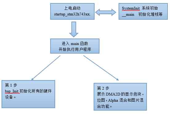
The first 1 Stage , Power on start-up phase :
- This part is in V7 The board BSP Driving tutorial 14 The chapter describes in detail .
The first 2 Stage , Get into main function :
- The first 1 Step , Hardware initialization , Mainly MPU,Cache,HAL library , The system clock , Tick timer ,LED ,LCD, and SDRAM.
- The first 2 Step ,DMA2D Part of application design , Main show DMA2D Brush the color block , Brush bitmap ,Alpha Blending and image blending .
6.7 Experiment routine description
Supporting examples :
V7-2003_DMA2D
The experiment purpose :
- Study DMA2D Show color blocks , Bitmap ,Alpha Mix and picture mix, etc .
Experimental content :
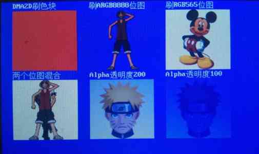
- start-up 1 individual 200ms Auto reset timer for , Give Way LED2 Every time 200ms Flip once .
- The first 1 Map : Use DMA2D Brush the color block .
- The first 2 Map : Show ARGB8888 Bitmap .
- The first 3 Map : Show RGB565 Bitmap .
- The first 4 Map : Two bitmaps mixed .
- The first 5 Map :Alpha transparency 200 The bitmap shows .
- The first 6 Map :Alpha transparency 100 The bitmap shows .
LCD The interface display effect is as follows :
6.8 summary
The knowledge points covered in this chapter are very important , I hope beginners must master , Because later chapters use LCD You need to use it all the way up DMA2D.

![[graffiti Internet of things footprint] graffiti cloud platform interface description](/img/f9/521c69fed884058e3800af0ea06bc0.jpg)

