当前位置:网站首页>【JokerのZYNQ7020】DDS_ Compiler。
【JokerのZYNQ7020】DDS_ Compiler。
2022-07-03 17:09:00 【Joker_ It's Xiao Wang.】
Software environment :vivado 2019.1 Hardware platform :XC7Z020
There are two common methods for self generated sine and cosine data sources , One is through matlab Generate coe Deposit in ram in , Broadcast when using , The other is through its own DDS Nuclear generation , Let's talk about it today DDS_Compiler This IP Usage of core and matters needing attention , Refer to the manual for the following contents pg141, Friends who like the original flavor can download and check .
The internal structure of the nucleus is as follows .
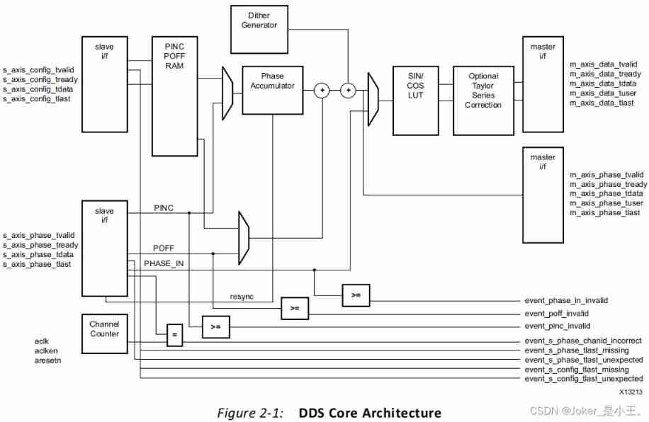
The next thing is right DDS Explain the meaning of parameter configuration .

parameter selection in , There are two options , Respectively system parameters and hardware parameters, When selecting different parameter configuration methods , The configuration items below will be different , It is mainly set for the convenience of system designers who are more concerned about the frequency domain or design engineers who are more concerned about the hardware part .
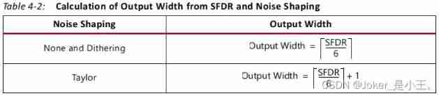
When choosing system parameters when , The following parameters include dynamic spurious range 、 Frequency resolution and adding noise shapes , among ,SFDR Related to the selected noise shape , The relationship between it and the output bit width is shown in the following table :
Frequency resolution here is an example , If the system clock is 120MHz, The bit width of the phase accumulator is 32 position , that , The corresponding frequency resolution is 0.0279396Hz.

When parameter selection Choose as hardware parameters when , The following parameters become data bit width and phase bit width .

Next is the configuration item on the second page .
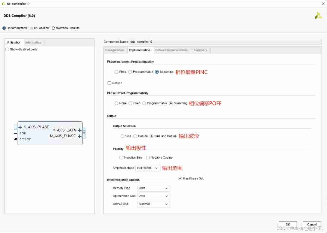
The first is phase increment and phase offset , That is what the manual says PINC and POFF,none and fixed Needless to say, of course , For not using and fixed values , When choosing programmable when , There will be more on the left s_axis_config Configuration port , When choosing streaming when , There will be more on the left s_axis_phase Configuration port , Next, we will focus on PINC、POFF And these two configuration ports .
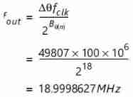
PINC That is, the increase of the phase accumulator every time the system clock comes , When the system clock is 100MHz, The output bit width is 18, At this time, if you want to output 19M Waveform of , be PINC The incremental calculation method is as follows :

because PINC The value of can only be positive , So when PINC by 49807 when , At present DDS The actual output frequency of is :
as for POFF, Although the calculation formula is not directly given in the manual , But by PINC Calculation method and simulation , We can also roughly deduce the calculation method , Here, assume that the angle value you want to offset is  :
:

Finally in the n The phase of the clock cycle output of the system is :

The explanation is over PINC And POFF, And then to s_axis_config And s_axis_phase Describe the requirements of the configuration port . The first is to choose programmable After that s_axis_config passageway :
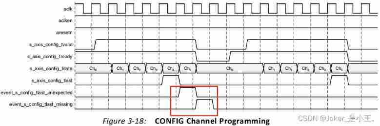
When there are multiple channels , Configure the channels in turn , And when the last channel is configured , Set up tlast The signal , Only then can all configurations be considered valid , Otherwise, the transmission is configured for the first time as shown in the figure above , When the penultimate channel is configured, it is pulled up tlast The signal , Lead to unexpected Signals and missing Signal set , Configuration failed .
When phase_width by 11 when , The data format of the configuration channel is as follows :

In choosing streaming After that s_axis_phase passageway , every last valid Effective phase_data Input , There will be one data Output , It can be used to dynamically adjust the frequency of output waveform , When phase_width by 11 when ,phase_data The format is as follows :

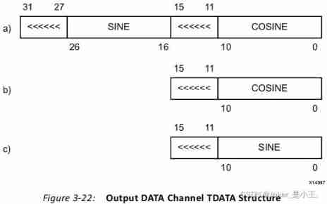
That's it PINC、POFF After these precautions , Say about the data output format , It is also output 11 Bit width data , among <<<<<< Is an extension of the sign bit :
Next, there are the remaining items on the configuration page , I use default parameters :

At the end of the summary Configuration and resource usage can be seen in :

Next, try simulation , The simulation file is as follows .
module dds_tb();
reg clk;
reg rst_n;
reg [31:0] phase_pinc;
reg [31:0] phase_poff;
reg phase_tvalid;
reg [31:0] phase_tdata;
wire data_valid;
wire [15:0] cos_out;
wire [15:0] sin_out;
wire phase_valid;
wire [15:0] phase_out;
initial begin
#0 clk = 0;
rst_n = 1'b0;
phase_pinc = 32'd0;
phase_poff = 32'd0;
phase_tvalid = 1'b0;
phase_tdata = 32'd0;
#1000 rst_n = 1'b1;
phase_tvalid = 1'b1;
phase_pinc = 32'd1311;
phase_poff = 32'h0000_0000;
phase_tdata = phase_poff + phase_pinc;
end
always #5 clk = ~clk;
dds_compiler_0 dds_compiler_0 (
.aclk(clk), // input wire aclk
.aresetn(rst_n), // input wire aresetn
.s_axis_phase_tvalid(phase_tvalid), // input wire s_axis_phase_tvalid
.s_axis_phase_tdata(phase_tdata), // input wire [31 : 0] s_axis_phase_tdata
.m_axis_data_tvalid(data_valid), // output wire m_axis_data_tvalid
.m_axis_data_tdata({sin_out,cos_out}), // output wire [31 : 0] m_axis_data_tdata
.m_axis_phase_tvalid(phase_valid), // output wire m_axis_phase_tvalid
.m_axis_phase_tdata(phase_out) // output wire [15 : 0] m_axis_phase_tdata
);
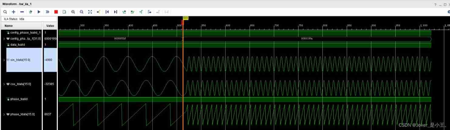
endmodulesys_clk 100M, Output 2M, The simulation results are as follows .
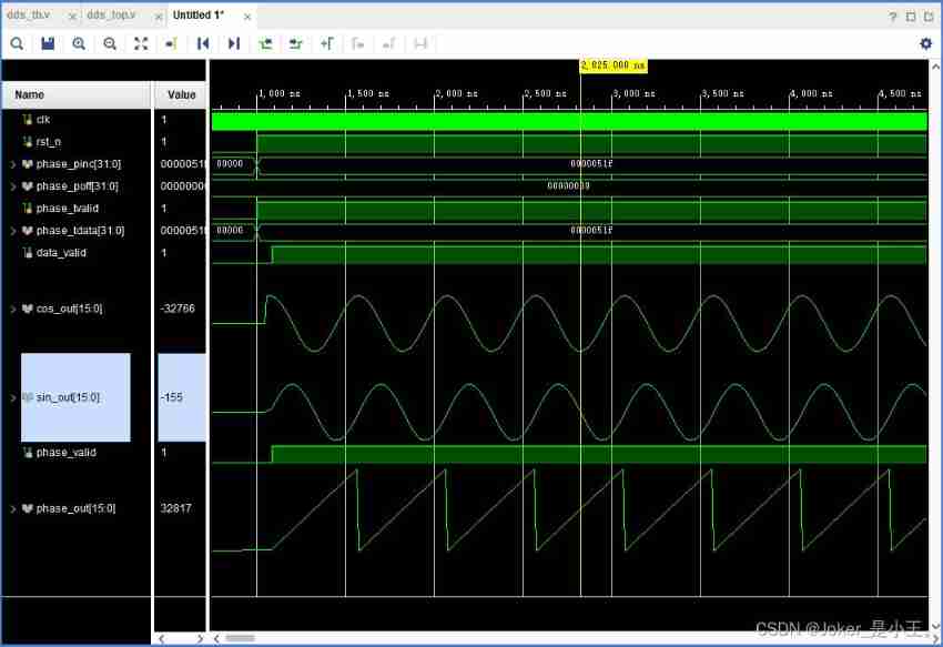
The following will POFF Set to 16‘h’4000_0000 Shift the phase 90° after , The simulation results are as follows .

In fact, the board results are as follows , Through real-time adjustment PINC value , To dynamically adjust the output waveform frequency , from 2M To adjust to 10M.
Last , Just to add :
1. According to the law of sampling , The frequency of the output waveform should not be greater than that of the input clock 1/2, Otherwise, the output frequency is incorrect
2. From the simulation results , stay POFF by 0, Output data_tvalid The first point corresponding to valid , Not at all sin At the beginning of the waveform 0 spot , It's just an accidental discovery , It should have no effect on continuous waveform

边栏推荐
- How to delete a specific line from a text file using the SED command?
- Squid service startup script
- Mysql database -dql
- Meituan side: why does thread crash not cause JVM crash
- vs code 插件 koroFileHeader
- SVN完全备份svnadmin hotcopy
- [2. Basics of Delphi grammar] 1 Identifiers and reserved words
- 基于主机的入侵系统IDS
- CC2530 common registers
- [error reporting] omp: error 15: initializing libiomp5md dll, but found libiomp5md. dll already initialized.
猜你喜欢
C language modifies files by line
Mysql database DDL and DML

Pools de Threads: les composants les plus courants et les plus sujets aux erreurs du Code d'affaires

Static program analysis (I) -- Outline mind map and content introduction
ucore概述

【RT-Thread】nxp rt10xx 设备驱动框架之--hwtimer搭建和使用

人生还在迷茫?也许这些订阅号里有你需要的答案!
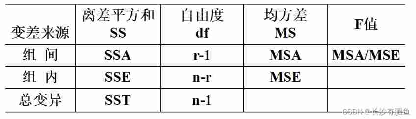
Analysis of variance summary
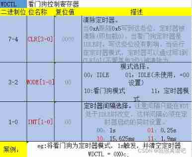
CC2530 common registers for watchdog
UCORE overview
随机推荐
27. Input 3 integers and output them in descending order. Pointer method is required.
[combinatorics] recursive equation (characteristic equation and characteristic root | example of characteristic equation | root formula of monadic quadratic equation)
Apache服务挂起Asynchronous AcceptEx failed.
What is your income level in the country?
線程池:業務代碼最常用也最容易犯錯的組件
An example of HP array card troubleshooting
C语言按行修改文件
C language string practice
网络硬盘NFS的安装与配置
13mnnimo5-4 German standard steel plate 13MnNiMo54 boiler steel 13MnNiMo54 chemical properties
Design e-commerce spike
Answer to the homework assessment of advanced English reading (II) of the course examination of Fuzhou Normal University in February 2022
【RT-Thread】nxp rt10xx 设备驱动框架之--Pin搭建和使用
RedHat 6.2 configuring ZABBIX
[combinatorics] recursive equation (outline of recursive equation content | definition of recursive equation | example description of recursive equation | Fibonacci Series)
Free data | new library online | cnopendata complete data of China's insurance intermediary outlets
LeetCode 1658. Minimum operand to reduce x to 0
Rsync remote synchronization
Static program analysis (I) -- Outline mind map and content introduction
远程办公之如何推进跨部门项目协作 | 社区征文