当前位置:网站首页>[quick start to digital IC Verification] 8. Typical circuits in digital ICs and their corresponding Verilog description methods
[quick start to digital IC Verification] 8. Typical circuits in digital ICs and their corresponding Verilog description methods
2022-07-05 20:10:00 【luoganttcc】
Reading guide : The author has the honor to be a pioneer in the field of electronic information in China “ University of electronic technology ” During postgraduate study , Touch the cutting edge Numbers IC Verification knowledge , I heard something like Huawei Hisilicon 、 Tsinghua purple light 、 MediaTek technology And other top IC related enterprises in the industry , Pairs of numbers IC Verify some knowledge accumulation and learning experience . Want to get started for help IC Verified friends , After one or two thoughts , This column is specially opened , In order to spend the shortest time , Take the least detours , Most learned IC Verify technical knowledge .
List of articles
- One 、 Hardware description language
- Two 、 Typical circuits
- 2.1、 Combinational logic circuit : Full adder
- 2.2、 Combinational logic circuit : One out of four selector
- 2.3、 Combinational logic circuit :38 Decoder
- 2.4、 Combinational logic circuit : Logical operation
- 2.5、 Combinational logic circuit : Shift operation
- 2.6、 Sequential logic circuit : Counter
- 2.7、 Sequential logic circuit : Asynchronous reset D trigger
- 2.8、 Sequential logic circuit : Synchronous reset D trigger
- 2.9、 Sequential logic circuit : complex D trigger ( Use less )
- 3、 ... and 、TestBench function
- Four 、 Verify the four elements
- 5、 ... and 、fulladd_tb example
- Reference resources
One 、 Hardware description language
- HDL The mainstream language of
- VHDL
- Verilog
- SystemVerilog
- The level of hardware description
- Gate level (Gate-Level)【 Integrable 】
- Register transfer level (RTL-Level)【 Integrable 】
- Behavior level 【 Not necessarily comprehensive 】
- RTL:Register Transfer Level
- Integrability
- Readability
Two 、 Typical circuits
2.1、 Combinational logic circuit : Full adder
module fulladd(
    input   wire    ain,
    input   wire    bin,
    input   wire    cin,

    output  wire    sum,
    output  wire    cout
);

assign sum  = ain ^ bin ^ cim;
assign cout = (ain & bin) | (bin & cin) | (ain & cin);

endmodule
- stay assign The variable type assigned in must be wire type
- stay always or initial The assignment in must be reg type
2.2、 Combinational logic circuit : One out of four selector
module mux_4_1(
    input   wire            C,
    input   wire            D,
    input   wire            E,
    input   wire            F,

    input   wire    [1:0]   S,

    input   reg             Mux_out
);

[email protected](C or D or E or F or S)
begin
    case(S)
        2'b00 : Mux_out = C;
        2'b01 : Mux_out = D;
        2'b10 : Mux_out = E;
        default : Mux_out = F;
    endcase
end

endmodule
2.3、 Combinational logic circuit :38 Decoder
[email protected](enable or ain) begin if(!enable) yout = 8'b0; else case(ain) 3'b000 : yout = 8'b0000_0001; 3'b001 : yout = 8'b0000_0010; 3'b010 : yout = 8'b0000_0100; 3'b011 : yout = 8'b0000_1000; 3'b100 : yout = 8'b0001_0000; 3'b101 : yout = 8'b0010_0000; 3'b110 : yout = 8'b0100_0000; 3'b111 : yout = 8'b1000_0000; endcase end- Learn the above exclusive code
- Be careful
land1It's different ! 2.4、 Combinational logic circuit : Logical operation
[email protected](A or B)
begin
    Q1 = A > B;
    Q2 = A < B;
    Q3 = A >= B;
end

// Q3 = A >= B;  Equivalent to the following code

if(A >= B)
    Q3 = 1
else
    Q3 = 0;
2.5、 Combinational logic circuit : Shift operation
2.5、 Combinational logic circuit : Shift operation
module shift(
    input   wire    [3:0]   data,

    output   reg    [3:0]   q1,
    output   reg    [3:0]   q2,
);

parameter B = 2;

[email protected](data)
begin
    q1 = data << B;// Move left
    q2 = data >> B;// Move right
end

endmodule
2.6、 Sequential logic circuit : Counter
module count_en( input wire clock, input wire reset, input wire enable, output reg [WIDTH-1 : 0] out ); parameter WIDTH = 8; parameter UDLY = 1; [email protected](posedge clock or negedge reset) begin if(!reset) out <= 8'b0; else if(enable) out <= #UDLY out + 1; // Analog device delay , Generally speaking, it is not advocated end endmodule- Sequential logic assignment , To assign with non blocking
2.7、 Sequential logic circuit : Asynchronous reset D trigger
module dff_async_pre( input wire data, input wire clk, input wire preset, output reg q ); parameter U_DLY = 1; [email protected](posedge clk or negedge preset)// Asynchronous reset begin if(~preset) q <= #U_DLY 1'b1; else q <= #U_DLY data; end endmodule- if/else Priority exists
2.8、 Sequential logic circuit : Synchronous reset D trigger
module dff_sync_rst(
    input   wire    data,
    input   wire    clk,
    input   wire    reset,

    output  reg     q
);

parameter U_DLY = 1;

[email protected](posedge clk)// Synchronous reset
begin
    if(!reset)
        q <= #U_DLY 1'b0;
    else
        q <= #U_DLY data;
end

endmodule
2.9、 Sequential logic circuit : complex D trigger ( Use less )
module dff_sync(
    input   wire    data,
    input   wire    clk,
    input   wire    reset,
    input   wire    preset,

    output  reg     q
);

parameter U_DLY = 1;

[email protected](posedge clk or negedge reset or negedge preset)// Synchronous reset + Asynchronous reset
begin
    if(~reset)
        q <= 1'b0;
    else if(~preset)
        q <= 1'b1;
    else
        q <= #U_DLY data;
end

endmodule
3、 ... and 、TestBench function
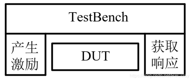
- Generate incentives Generate stimulus
- Input the excitation into the design to be tested (DUT - Design Under Test)
- Generate expectations Generate Expectation
- Get a response (Capture response)
- Check the correctness of the response (Check the response for correctness)
- For complex TestBench, If used later SystemVerilog Written TestBench( namely SVTB), Most need to be in TestBench Add Reference Module(RM), Then introduce incentives into RM Module , And will RM Save the output of , Then compare with the result of response output (check). If the results are the same , Then the use case passes ; If it's not right , that DUT or RM There may be a problem , It needs to be rechecked .
- about VTB, The test object is relatively small , The function is relatively simple and usually does not need to be added RM.
- RM The logical behavior of DUT equally , But there is no delay information !
- Evaluate the validation progress according to the validation objectives (Measure the progress against the overall verification goals)
- The core idea of verification : Verify completeness , It's not just about finding BUG
- prove DUT The function is ok Of , So first of all DUT Function point of (Feature) Completely decompose ! Then verify whether each function point ok, If error, Then you have to find BUG.
- The verification progress needs to be seen coverage CDV(Coverage Driven Verification), There are usually two kinds : Functional coverage 【 subjective 】( Decompose function points , Each function point needs to be verified ,= 100%)、 Code coverage 【 objective 】( There may be redundant code , Some codes will fail ,<100%)
notes : The input signal is called incentive , The different combinations of input incentives are called Different Pattern, Also called Test point (Test Pattern). The output signal is called Respond to .
Four 、 Verify the four elements
- 1、 Irrigation stimulation : Generate input signal
- 2、 Make expectations : Produce the desired results
- Reference Model, Referred to as RM
- 3、 Set response : Collect the output signal
- 4、 compare : Comparison results
- Purpose : Verify the result comparison automation
5、 ... and 、fulladd_tb example
`timescale 1ns/1ps
module fulladd_tb;
    reg ain, bin, cin;

    wire cout, sum;

    reg clk;
    always #1 clk = ~clk; // The clock here is useless , The full adder is just a combinational logic

    // Generate incentives
    initial
    begin
        clk = 0;

        ain = 0;
        bin = 1;
        cin = 1;
        #10
        ain = 1;
        bin = 1;
        cin = 0;
        #10
        ain = 1;
        bin = 1;
        cin = 1;
        #10
        $finish;
    end

    // Collect responses
    initial
    begin
        #5;
        if(sum!=0)  $display("sum calc ERROR!!!, sum = %b", sum);
        else        $display("SUM calc correct!!!");
        if(cout!=1)$display("cout clac ERROR!!!, cout = %b", cout);
        else        $display("cout calc correct!!!");
        #10;
        if(sum!=0)  $display("sum calc ERROR!!!, sum = %b", sum);
        else        $display("SUM calc correct!!!");
        if(cout!=1)$display("cout clac ERROR!!!, cout = %b", cout);
        else        $display("cout calc correct!!!");
        #10
        if(sum!=1)  $display("sum calc ERROR!!!, sum = %b", sum);
        else        $display("SUM calc correct!!!");
        if(cout!=1)$display("cout clac ERROR!!!, cout = %b", cout);
        else        $display("cout calc correct!!!");
    end

    // Exemplification
    fulladd u0_fulladd(
        .cout   (cout),
        .sum    (sum),
        .ain    (ain),
        .bin    (bin),
        .cin    (cin)
    );

endmodule
Reference resources
【FPGA Basics 】 A quick start Verilog Basic knowledge of ( Summary )
边栏推荐
- 浅浅的谈一下ThreadLocalInsecureRandom
- CCPC 2021威海 - G. Shinyruo and KFC(组合数,小技巧)
- Some problems encountered in cocos2d-x project summary
- Using repositoryprovider to simplify the value passing of parent-child components
- 函数的概念及语法
- 【数字IC验证快速入门】7、验证岗位中必备的数字电路基础知识(含常见面试题)
- 解决php无法将string转换为json的办法
- 银河证券在网上开户安全吗?
- Solve the problem that the database configuration information under the ThinkPHP framework application directory is still connected by default after modification
- 【数字IC验证快速入门】1、浅谈数字IC验证,了解专栏内容,明确学习目标
猜你喜欢
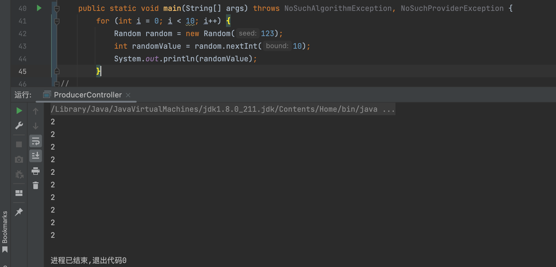
Securerandom things | true and false random numbers
How to safely and quickly migrate from CentOS to openeuler
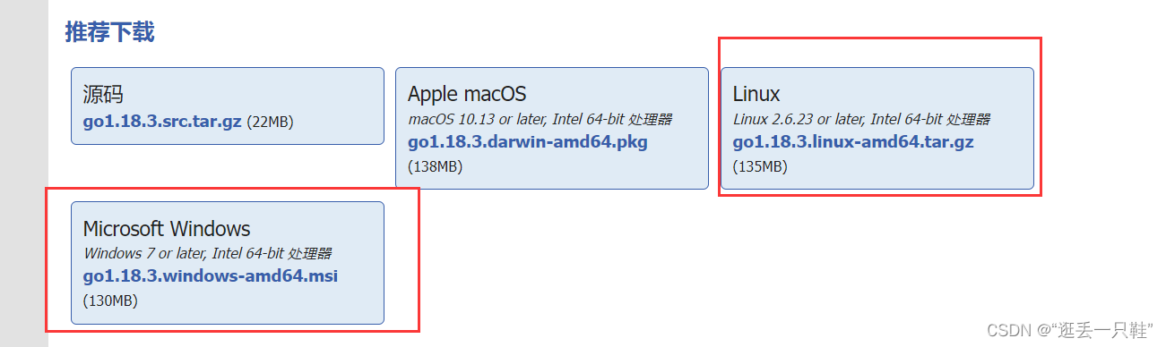
Go language | 01 wsl+vscode environment construction pit avoidance Guide

Leetcode brush questions: binary tree 11 (balanced binary tree)
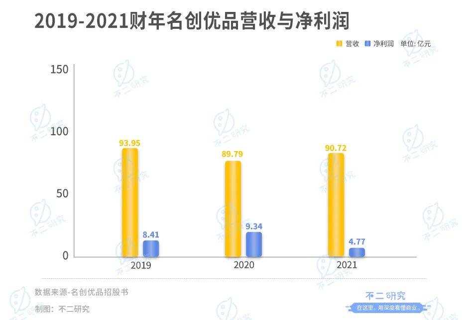
Hong Kong stocks will welcome the "best ten yuan store". Can famous creative products break through through the IPO?

Wechat applet regular expression extraction link

解决php无法将string转换为json的办法
Go language | 03 array, pointer, slice usage
港股将迎“最牛十元店“,名创优品能借IPO突围?
Autumn byte interviewer asked you any questions? In fact, you have stepped on thunder
随机推荐
Parler de threadlocal insecurerandom
Codeforces Round #804 (Div. 2) - A, B, C
618 "low key" curtain call, how can baiqiushangmei join hands with the brand to cross the "uncertain era"?
函数的概念及语法
怎么挑选好的外盘平台,安全正规的?
DP: tree DP
Concept and syntax of function
CCPC 2021威海 - G. Shinyruo and KFC(组合数,小技巧)
1: Citation;
Android interview classic, 2022 Android interview written examination summary
Is it safe for Galaxy Securities to open an account online?
Wechat applet regular expression extraction link
Debezium series: record the messages parsed by debezium and the solutions after the MariaDB database deletes multiple temporary tables
Go language | 01 wsl+vscode environment construction pit avoidance Guide
js方法传Long类型id值时会出现精确损失
什么是pyc文件
Process file and directory names
JS implementation prohibits web page zooming (ctrl+ mouse, +, - zooming effective pro test)
深度学习 卷积神经网络(CNN)基础
leetcode刷题:二叉树18(最大二叉树)