当前位置:网站首页>Ncp1342 chip substitute pn8213 65W gallium nitride charger scheme
Ncp1342 chip substitute pn8213 65W gallium nitride charger scheme
2022-07-05 11:36:00 【Shenzhen Oceanwide Microelectronics Co., Ltd】
FS68001 encapsulation SOP8 The wireless charging system includes primary and secondary coils , Coupled to each other by electromagnetic fields . The ferrite of the two coils as part of its structure further limits the field coupling . The primary coil is from AD-DC The adapter supplies power to the transmitter to drive the transmitter with a switching waveform . The secondary coil is connected to the rectifier and can output directly from the battery or electronic charger or secondary voltage stabilizing connection . In the system, the capacitor and the coil are connected in series to produce resonance , Better transmission . In the resonant system, it is easy to control the transmission power by frequency conversion .WM1212 Frequency and pulse width modulation methods are used to control power transmission . When the operating frequency is close to 205KHz And when the receiver has low power ,WM1212 Reduce PWM Duty cycle adjustment output . The output voltage of the rectifier is generated by the secondary microprocessor to control the modulation and coding information to monitor from the secondary side to the primary side . The encoded information is composed of packets , There are boot bytes 、 Header byte 、 Information byte and check byte . according to WPC standard , Packets can be associated with identification , To configure , Control error , Rectifier power supply , Charging state , And power transmission end information .
Support Android and iphone 8 Mobile phone 5W Wireless charging chip
One summary
The wireless charging system includes primary and secondary coils , Coupled to each other by electromagnetic fields . The ferrite of the two coils as part of its structure further improves the field coupling . The primary coil is from AD-DC The adapter supplies power to the transmitter to drive the transmitter with a switching waveform . The secondary coil is connected to the rectifier and can output directly from the battery or electronic charger or secondary voltage stabilizing connection . In the system, the capacitor and the coil are connected in series to produce resonance , Better transmission . In the resonant system, it is easy to control the transmission power by frequency conversion .WM1212 Frequency and pulse width modulation methods are used to control power transmission . When the operating frequency is close to 205KHz And when the receiver has low power ,WM1212 Reduce PWM Duty cycle adjustment output . The output voltage of the rectifier is generated by the secondary microprocessor to control the modulation and coding information to monitor from the secondary side to the primary side . The encoded information is composed of packets , There are boot bytes 、 Header byte 、 Information byte and check byte . according to WPC standard , Packets can be associated with identification , To configure , Control error , Rectifier power supply , Charging state , And power transmission end information .
Two application
2 characteristic
2.1 Main specifications and parameters
l Intelligently control the transmission power between the base station and the mobile device
l Comply with wireless power (WPC) as follows
n WPC1.1 Foreign object detection (FOD)
n WPC1.0 Parasitic metal detection (PMOD)
l Parasitic metal detection is used to improve security during wireless power transmission
l Operation status indication
n standby
n Transmission power
n Charging complete
n fault
2.2 Application circuit characteristics
l Dynamic power limitation (DPL) It can be from a limited current 5-V Power supply ( for example :USB port )
l The transmitter coil supplies correction information to the receiver
l Input power 5V
l standard WPC Non magnetic emission coil
l LED Indicates power transmission or fault status
l The sound indicates that the transmission power needs to add a buzzer on the board
2.3 application
WM1212-M The demo module is wm1212-M The transmitting part of the wireless charging system . The transmitting module provides WM1212-M The transmitter of the receiver .wm1212-M The module needs one that can achieve 2A Of 5 V Power supply to the transmitting circuit 、LED Indicator light 、 Transmitting coil on circuit board . The module has the following characteristics :
• Dynamic power limitation (DPL) From a finite current 5V Power supply ( for example :USB port ).
• The transmitter coil provides the receiver information
• Input power 5 V
• standard WPC A11 Non magnetic emission coil
• LED Indicates power transmission or fault status
• The sound indicates that the transmission power needs to add a buzzer on the board
边栏推荐
- 《看完就懂系列》15个方法教你玩转字符串
- 石油化工企业安全生产智能化管控系统平台建设思考和建议
- COMSOL--三维图形的建立
- pytorch-多层感知机MLP
- 程序员内卷和保持行业竞争力
- Open3D 网格(曲面)赋色
- 12. (map data) cesium city building map
- The ninth Operation Committee meeting of dragon lizard community was successfully held
- What does cross-border e-commerce mean? What do you mainly do? What are the business models?
- MySQL statistical skills: on duplicate key update usage
猜你喜欢

谜语1

Ziguang zhanrui's first 5g R17 IOT NTN satellite in the world has been measured on the Internet of things
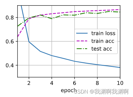
pytorch-多层感知机MLP
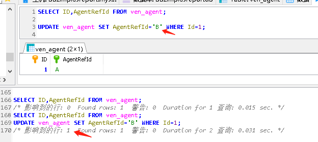
MySQL giant pit: update updates should be judged with caution by affecting the number of rows!!!

7 大主题、9 位技术大咖!龙蜥大讲堂7月硬核直播预告抢先看,明天见
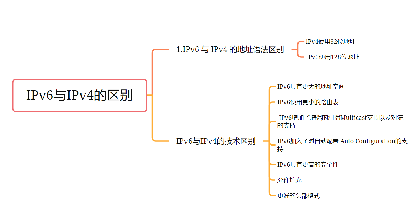
Differences between IPv6 and IPv4 three departments including the office of network information technology promote IPv6 scale deployment
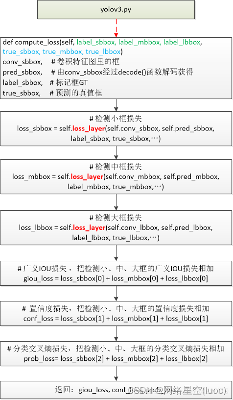
【yolov3损失函数】
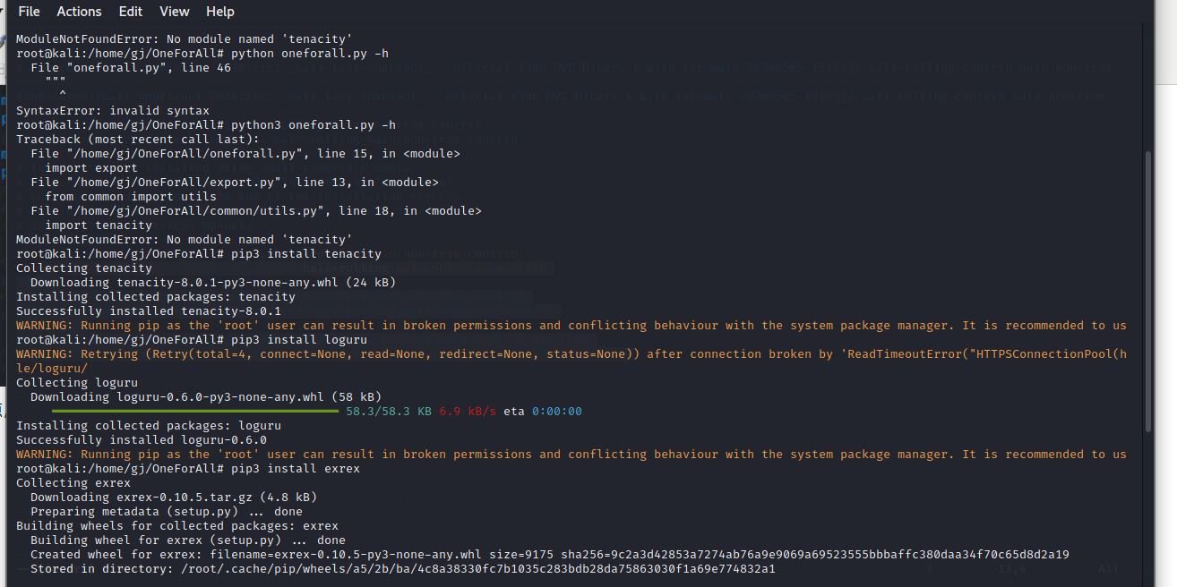
OneForAll安装使用
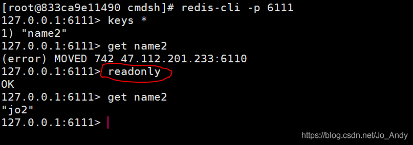
简单解决redis cluster中从节点读取不了数据(error) MOVED

Oneforall installation and use
随机推荐
COMSOL -- 3D casual painting -- sweeping
Unity xlua monoproxy mono proxy class
Cdga | six principles that data governance has to adhere to
管理多个Instagram帐户防关联小技巧大分享
Home office things community essay
871. Minimum Number of Refueling Stops
简单解决redis cluster中从节点读取不了数据(error) MOVED
DDoS attack principle, the phenomenon of being attacked by DDoS
redis主从模式
Spark Tuning (I): from HQL to code
pytorch-权重衰退(weight decay)和丢弃法(dropout)
Web API configuration custom route
解决readObjectStart: expect { or n, but found N, error found in #1 byte of ...||..., bigger context ..
跨境电商是啥意思?主要是做什么的?业务模式有哪些?
Redis集群的重定向
MySQL statistical skills: on duplicate key update usage
12. (map data) cesium city building map
Error assembling WAR: webxml attribute is required (or pre-existing WEB-INF/web.xml if executing in
[crawler] bugs encountered by wasm
Risc-v-qemu-virt in FreeRTOS_ Scheduling opportunity of GCC